fuel cap YAMAHA TMAX 2016 Owners Manual
[x] Cancel search | Manufacturer: YAMAHA, Model Year: 2016, Model line: TMAX, Model: YAMAHA TMAX 2016Pages: 110, PDF Size: 6.26 MB
Page 5 of 110

Table of contents
Safety information............................ 1-1
Further safe-riding points ................ 1-5
Description ........................................ 2-1
Left view .......................................... 2-1
Right view ........................................ 2-2
Controls and instruments ................ 2-3
Smart key system ............................. 3-1
Smart key system ............................ 3-1
Operating range of the smart key system............. ....................... ...... 3-2
Handling of the smart key and
mechanical key ............................ 3-3
Smart key ........................................ 3-5
Replacing the smart key battery ...... 3-6
Vehicle power on and steering lock release .................................. 3-8
Powering off the vehicle .................. 3-9
How to lock the steering ................ 3-10
Seat opening and closing .............. 3-10
Parking mode ................................ 3-11
Instrument and control functions ... 4-1
Indicator lights and warning lights ... 4-1
Speedometer .............. ..................... 4-2
Tachometer ..................................... 4-3
Multi-function display ....................... 4-3
Handlebar switches ....................... 4-10
Front brake lever ........................... 4-11
Rear brake lever ............................ 4-12
Rear brake lock lever .................... 4-12
ABS (for ABS models) ................... 4-13
Fuel tank cap ................................. 4-14
Fuel ............................................... 4-15
Catalytic converter......................... 4-16
Adjusting the rider backrest ........... 4-17
Helmet holder ................................ 4-17
Storage compartments .................. 4-18
Windshield ..................................... 4-19
Rear view mirrors .......................... 4-21
Shock absorber assembly ............. 4-21
Sidestand ...................................... 4-22
Ignition circuit cut- off system ......... 4-22
Auxiliary DC jack ........................... 4-24 For your safety – pre-operation
checks
............................................... 5-1
Operation and important riding
points ................................................. 6-1
Starting the engine .......................... 6-2
Starting off....................................... 6-3
Acceleration and deceleration......... 6-3
Braking ............................................ 6-4
Tips for reducing fuel
consumption ................................ 6-5
Engine break-in ............................... 6-5
Parking ............................................ 6-6
Periodic maintenance and
adjustment ........................................ 7-1
Owner’s tool kit ............................... 7-2
Periodic maintenance chart for the emission control system ........ 7-3
General maintenance and lubrication chart ........................... 7-4
Removing and installing panels ...... 7-7
Checking the spark plugs................ 7-9
Engine oil and oil filter cartridge .... 7-10
Coolant.......................................... 7-13
Replacing the air filter element ..... 7-15
Adjusting the engine idling speed ......................................... 7-16
Checking the throttle grip free play ............................................ 7-16
Valve clearance ............................ 7-17
Tires .............................................. 7-17
Cast wheels .................................. 7-19
Checking the front and rear brake lever free play .................. 7-20
Adjusting the rear brake lock
cable .......................................... 7-21
Checking the rear brake lock ........ 7-21
Checking the front and rear
brake pads ................................. 7-22
Checking the brake fluid level ....... 7-22
Changing the brake fluid ............... 7-23
Drive belt slack.............................. 7-24
Checking and lubricating the cables ........................................ 7-24
2PW-9-E1.book 1 ページ 2015年9月10日 木曜日 午後5時17分
Page 13 of 110
Description
2-2
1
2
3
4
5
6
7
8
9
10
11
12
13
14
EAU63391
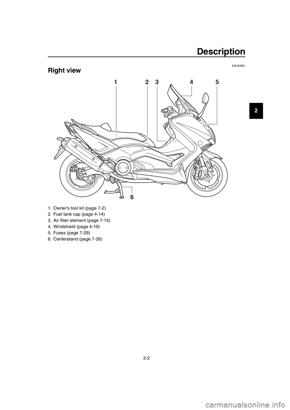
Right view
1. Owner’s tool kit (page 7-2)
2. Fuel tank cap (page 4-14)
3. Air filter element (page 7-15)
4. Windshield (page 4-19)
5. Fuses (page 7-29)
6. Centerstand (page 7-26)
3
6
1542
2PW-9-E1.book 2 ページ 2015年9月10日 木曜日 午後5時17分
Page 20 of 110
Smart key system
3-6
1
2
3
4
5
6
7
8
9
10
11
12
13
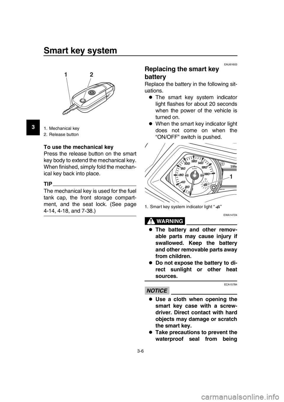
14 To use the mechanical key
Press the release button on the smart
key body to extend the mechanical key.
When finished, simply fold the mechan-
ical key back into place.
TIP
The mechanical key is used for the fuel
tank cap, the front storage compart-
ment, and the seat lock. (See page
4-14, 4-18, and 7-38.)
EAU61603
Replacing the smart key
battery
Replace the battery in the following sit-
uations.
The smart key system indicator
light flashes for about 20 seconds
when the power of the vehicle is
turned on.
When the smart key indicator light
does not come on when the
“ON/OFF” switch is pushed.
WARNING
EWA14724
The battery and other remov-
able parts may cause injury if
swallowed. Keep the battery
and other removable parts away
from children.
Do not expose the battery to di-
rect sunlight or other heat
sources.
NOTICE
ECA15784
Use a cloth when opening the
smart key case with a screw-
driver. Direct contact with hard
objects may damage or scratch
the smart key.
Take precautions to prevent the
waterproof seal from being
1. Mechanical key
2. Release button
12
1. Smart key system indicator light “ ”
1
2PW-9-E1.book 6 ページ 2015年9月10日 木曜日 午後5時17分
Page 39 of 110
Instrument and control functions
4-14
1
2
3
4
5
6
7
8
9
10
11
12
13
14
EAU63691
Fuel tank cap
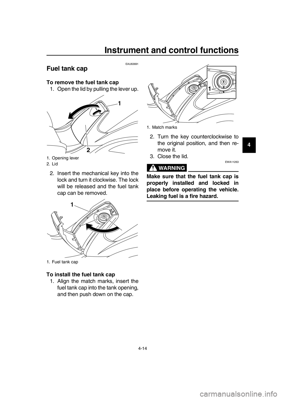
To remove the fuel tank cap 1. Open the lid by pulling the lever up.
2. Insert the mechanical key into the lock and turn it clockwise. The lock
will be released and the fuel tank
cap can be removed.
To install the fuel tank cap 1. Align the match marks, insert the fuel tank cap into the tank opening,
and then push down on the cap. 2. Turn the key counterclockwise to
the original position, and then re-
move it.
3. Close the lid.
WARNING
EWA11263
Make sure that the fuel tank cap is
properly installed and locked in
place before operating the vehicle.
Leaking fuel is a fire hazard.
1. Opening lever
2. Lid
1. Fuel tank cap
1
2
1
1. Match marks
1
2PW-9-E1.book 14 ページ 2015年9月10日 木曜日 午後5時17分
Page 40 of 110
Instrument and control functions
4-15
1
2
3
4
5
6
7
8
9
10
11
12
13
14
EAU13222
Fuel
Make sure there is sufficient gasoline in
the tank.
WARNING
EWA10882
Gasoline and gasoline vapors are
extremely flammable. To avoid fires
and explosions and to reduce the
risk of injury when refueling, follow
these instructions. 1. Before refueling, turn off the en- gine and be sure that no one is sit-
ting on the vehicle. Never refuel
while smoking, or while in the vicin-
ity of sparks, open flames, or other
sources of ignition such as the pilot
lights of water heaters and clothes
dryers.
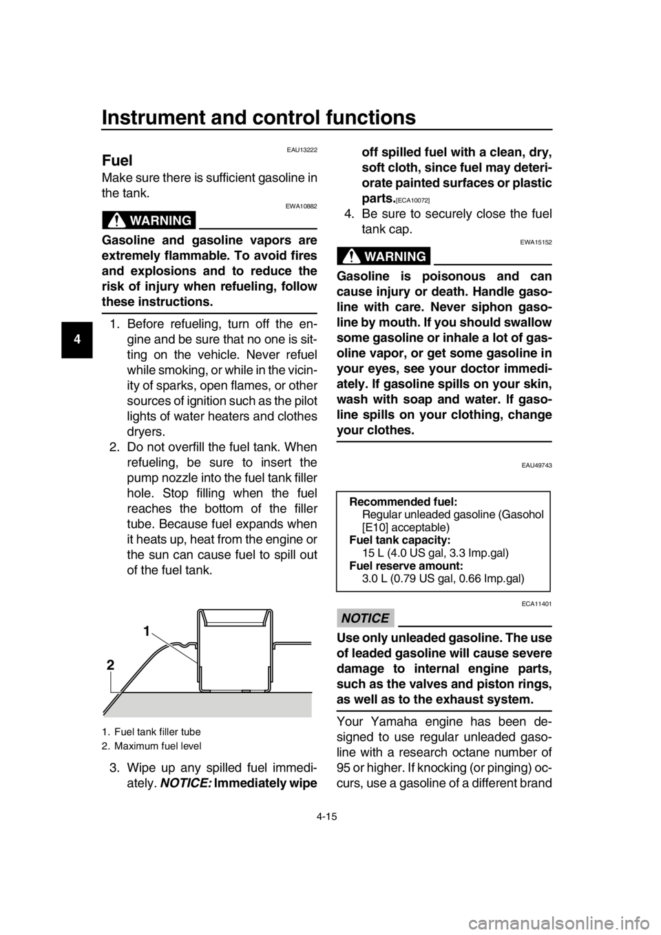
2. Do not overfill the fuel tank. When refueling, be sure to insert the
pump nozzle into the fuel tank filler
hole. Stop filling when the fuel
reaches the bottom of the filler
tube. Because fuel expands when
it heats up, heat from the engine or
the sun can cause fuel to spill out
of the fuel tank.
3. Wipe up any spilled fuel immedi- ately. NOTICE: Immediately wipe off spilled fuel with a clean, dry,
soft cloth, since fuel may deteri-
orate painted surfaces or plastic
parts.
[ECA10072]
4. Be sure to securely close the fuel
tank cap.
WARNING
EWA15152
Gasoline is poisonous and can
cause injury or death. Handle gaso-
line with care. Never siphon gaso-
line by mouth. If you should swallow
some gasoline or inhale a lot of gas-
oline vapor, or get some gasoline in
your eyes, see your doctor immedi-
ately. If gasoline spills on your skin,
wash with soap and water. If gaso-
line spills on your clothing, change
your clothes.
EAU49743
NOTICE
ECA11401
Use only unleaded gasoline. The use
of leaded gasoline will cause severe
damage to internal engine parts,
such as the valves and piston rings,
as well as to the exhaust system.
Your Yamaha engine has been de-
signed to use regular unleaded gaso-
line with a research octane number of
95 or higher. If knocking (or pinging) oc-
curs, use a gasoline of a different brand
1. Fuel tank filler tube
2. Maximum fuel level
2 1
Recommended fuel:
Regular unleaded gasoline (Gasohol
[E10] acceptable)
Fuel tank capacity:
15 L (4.0 US gal, 3.3 Imp.gal)
Fuel reserve amount: 3.0 L (0.79 US gal, 0.66 Imp.gal)
2PW-9-E1.book 15 ページ 2015年9月10日 木曜日 午後5時17分
Page 100 of 110
Scooter care and storage
8-4
1
2
3
4
5
6
7
8
9
10
11
12
13
14
EAU36554
Storage
Short-term
Always store your scooter in a cool, dry
place and, if necessary, protect it
against dust with a porous cover. Be
sure the engine and the exhaust sys-
tem are cool before covering the scoot-
er.
NOTICE
ECA10821
Storing the scooter in a poorly
ventilated room or covering it
with a tarp, while it is still wet,
will allow water and humidity to
seep in and cause rust.
To prevent corrosion, avoid
damp cellars, stables (because
of the presence of ammonia)
and areas where strong chemi-
cals are stored.
Long-term
Before storing your scooter for several
months: 1. Follow all the instructions in the “Care” section of this chapter.
2. Fill up the fuel tank and add fuel stabilizer (if available) to prevent
the fuel tank from rusting and the
fuel from deteriorating.
3. Perform the following steps to pro- tect the cylinders, piston rings, etc.
from corrosion.
a. Remove the spark plug caps and the spark plugs.
b. Pour a teaspoonful of engine oil into the spark plug bores.
c. Install the spark plug caps onto the spark plugs, and then place
the spark plugs on the cylinder head so that the electrodes are
grounded. (This will limit spark-
ing during the next step.)
d. Turn the engine over several
times with the starter. (This will
coat the cylinder walls with oil.)
e. Remove the spark plug caps from the spark plugs, and then
install the spark plugs and the
spark plug caps. WARNING!
To prevent damage or injury
from sparking, make sure to
ground the spark plug elec-
trodes while turning the en-
gine over.
[EWA10952]
4. Lubricate all control cables and the pivoting points of all levers and
pedals as well as of the sides-
tand/centerstand.
5. Check and, if necessary, correct the tire air pressure, and then lift
the scooter so that both of its
wheels are off the ground. Alterna-
tively, turn the wheels a little every
month in order to prevent the tires
from becoming degraded in one
spot.
6. Cover the muffler outlet with a plastic bag to prevent moisture
from entering it.
7. Remove the battery and fully charge it. Store it in a cool, dry
place and charge it once a month.
Do not store the battery in an ex-
cessively cold or warm place [less
than 0 C (30 F) or more than 30
C (90 F)]. For more information
on storing the battery, see page
7-28.
TIP
Make any necessary repairs before
2PW-9-E1.book 4 ページ 2015年9月10日 木曜日 午後5時17分
Page 102 of 110

9-1
1
2
3
4
5
6
7
8
9
10
11
12
13
14
Specifications
EAU69993Dimensions:
Overall length: 2200 mm (86.6 in)
Overall width: 775 mm (30.5 in)
Overall height:
1420/1475 mm (55.9/58.1 in)
Seat height: 800 mm (31.5 in)
Wheelbase: 1580 mm (62.2 in)
Ground clearance:
125 mm (4.92 in)
Minimum turning radius: 2.8 m (9.19 ft)
Weight:
Curb weight:
219 kg (483 lb) (XP500)
222 kg (489 lb) (XP500A)
Engine:
Combustion cycle:4-stroke
Cooling system: Liquid cooled
Valve train:
DOHC
Cylinder arrangement: Inline
Number of cylinders: 2-cylinder
Displacement:
530 cm
3
Bore stroke:
68.0 73.0 mm (2.68 2.87 in)
Compression ratio: 10.9 : 1
Starting system:
Electric starter
Lubrication system: Dry sump
Engine oil:
Recommended brand:YAMALUBE
SAE viscosity grades: 10W-40
Recommended engine oil grade:
API service SG type or higher, JASO stan-
dard MA Engine oil quantity:
Oil change:2.70 L (2.85 US qt, 2.38 Imp.qt)
With oil filter removal:
2.90 L (3.07 US qt, 2.55 Imp.qt)
Coolant quantity:
Coolant reservoir (up to the maximum level
mark): 0.27 L (0.29 US qt, 0.24 Imp.qt)
Radiator (including all routes): 1.50 L (1.59 US qt, 1.32 Imp.qt)
Air filter:
Air filter element:Oil-coated paper element
Fuel:
Recommended fuel:
Regular unleaded gasoli ne (Gasohol [E10]
acceptable)
Fuel tank capacity:
15 L (4.0 US gal, 3.3 Imp.gal)
Fuel reserve amount: 3.0 L (0.79 US gal, 0.66 Imp.gal)
Fuel injection:
Throttle body:
ID mark:59C1 00
Spark plug(s):
Manufacturer/model: NGK/CR7E
Spark plug gap: 0.7–0.8 mm (0.028–0.031 in)
Clutch:
Clutch type:Wet, centrifugal, multiple-disc
Drivetrain:
Primary reduction ratio:
1.000
Final drive: Belt
Secondary reduction ratio: 6.034 (52/32 x 36/22 x 59/26)
Transmission type: V-belt automatic
Chassis:
Frame type:
Diamond
Caster angle: 25.0
Trail: 92 mm (3.6 in)
2PW-9-E1.book 1 ページ 2015年9月10日 木曜日 午後5時17分
Page 107 of 110

11-1
1
2
3
4
5
6
7
8
9
10
11
12
13
14
Index
A
ABS (for ABS models) ...........................4-13
ABS warning light (for ABS models)........4-1
Acceleration and deceleration .................6-3
Air filter element, replacing ....................7-15
Auxiliary DC jack ...................................4-24
Auxiliary lights .......................................7-32
B
Battery ...................................................7-28
Brake fluid, changing .............................7-23
Brake fluid level, checking .....................7-22
Brake lever, front ...................................4-11
Brake lever, rear ....................................4-12
Brake levers, lubricating ........................7-25
Braking ....................................................6-4
C
Cables, checking and lubricating...........7-24
Care.........................................................8-1
Catalytic converter.................................4-16
Centerstand and sidestand, checking and lubricating .....................7-26
Coolant ..................................................7-13
D
Dimmer switch .......................................4-10
Drive belt slack ......................................7-24
E
Emergency mode ..................................7-38
Engine break-in .......................................6-5
Engine idling speed ...............................7-16
Engine oil and oil filter cartridge ............7-10
Engine serial number ............................10-1
Engine stop switch ................................4-10
Engine trouble warning light ....................4-1
F
Front and rear brake lever free play,
checking ..............................................7-20
Front and rear brake pads, checking.....7-22
Front fork, checking ...............................7-26
Fuel .......................................................4-15
Fuel consumption, tips for reducing ........6-5
Fuel tank cap .........................................4-14
Fuses, replacing ....................................7-29
H
Handlebar switches ...............................4-10
Hazard switch ........................................4-10
Headlights .............................................7-31
Helmet holder ........................................4-17
High beam indicator light .........................4-1
Horn switch............................................4-10
How to lock the steering ........................3-10
I
Identification numbers ........................... 10-1
Ignition circuit cut-off system................. 4-22
Indicator lights and warning lights ........... 4-1
K
Key, handling of smart and mechanical
key ........................................................ 3-3
L
License plate light bulb, replacing ......... 7-34
M
Maintenance and lubrication, periodic .... 7-4
Maintenance, emission control system ... 7-3
Matte color, caution................................. 8-1
Model label............................................ 10-2
Multi-function display .............................. 4-3
O
ON/Start switch ..................................... 4-10
Operating range of the smart key system .................................................. 3-2
P
Panels, removing and installing .............. 7-7
Parking .................................................... 6-6
Parking mode ........................................ 3-11
Part locations .......................................... 2-1
Pass switch ........................................... 4-10
Powering off the vehicle .......................... 3-9
R
Rear brake lock cable, adjusting ........... 7-21
Rear brake lock, checking..................... 7-21
Rear brake lock lever ............................ 4-12
Rear view mirrors .................................. 4-21
Rider backrest, adjusting ...................... 4-17
S
Safe-riding points .................................... 1-5
Safety information ................................... 1-1
Seat opening and closing...................... 3-10
Shock absorber assembly..................... 4-21
Sidestand .............................................. 4-22
Smart key ................................................ 3-5
Smart key battery, replacing ................... 3-6
Smart key system ................................... 3-1
Smart key system indicator light ............. 4-2
Spark plugs, checking ............................. 7-9
Specifications .......................................... 9-1
Speedometer .......................................... 4-2
Starting off............................................... 6-3
Starting the engine .................................. 6-2
Steering, checking ................................ 7-27
Storage ................................................... 8-4
Storage compartments.......................... 4-18
2PW-9-E1.book 1 ページ 2015年9月10日 木曜日 午後5時17分