oil level YAMAHA TMAX 2016 Owners Manual
[x] Cancel search | Manufacturer: YAMAHA, Model Year: 2016, Model line: TMAX, Model: YAMAHA TMAX 2016Pages: 110, PDF Size: 6.26 MB
Page 5 of 110

Table of contents
Safety information............................ 1-1
Further safe-riding points ................ 1-5
Description ........................................ 2-1
Left view .......................................... 2-1
Right view ........................................ 2-2
Controls and instruments ................ 2-3
Smart key system ............................. 3-1
Smart key system ............................ 3-1
Operating range of the smart key system............. ....................... ...... 3-2
Handling of the smart key and
mechanical key ............................ 3-3
Smart key ........................................ 3-5
Replacing the smart key battery ...... 3-6
Vehicle power on and steering lock release .................................. 3-8
Powering off the vehicle .................. 3-9
How to lock the steering ................ 3-10
Seat opening and closing .............. 3-10
Parking mode ................................ 3-11
Instrument and control functions ... 4-1
Indicator lights and warning lights ... 4-1
Speedometer .............. ..................... 4-2
Tachometer ..................................... 4-3
Multi-function display ....................... 4-3
Handlebar switches ....................... 4-10
Front brake lever ........................... 4-11
Rear brake lever ............................ 4-12
Rear brake lock lever .................... 4-12
ABS (for ABS models) ................... 4-13
Fuel tank cap ................................. 4-14
Fuel ............................................... 4-15
Catalytic converter......................... 4-16
Adjusting the rider backrest ........... 4-17
Helmet holder ................................ 4-17
Storage compartments .................. 4-18
Windshield ..................................... 4-19
Rear view mirrors .......................... 4-21
Shock absorber assembly ............. 4-21
Sidestand ...................................... 4-22
Ignition circuit cut- off system ......... 4-22
Auxiliary DC jack ........................... 4-24 For your safety – pre-operation
checks
............................................... 5-1
Operation and important riding
points ................................................. 6-1
Starting the engine .......................... 6-2
Starting off....................................... 6-3
Acceleration and deceleration......... 6-3
Braking ............................................ 6-4
Tips for reducing fuel
consumption ................................ 6-5
Engine break-in ............................... 6-5
Parking ............................................ 6-6
Periodic maintenance and
adjustment ........................................ 7-1
Owner’s tool kit ............................... 7-2
Periodic maintenance chart for the emission control system ........ 7-3
General maintenance and lubrication chart ........................... 7-4
Removing and installing panels ...... 7-7
Checking the spark plugs................ 7-9
Engine oil and oil filter cartridge .... 7-10
Coolant.......................................... 7-13
Replacing the air filter element ..... 7-15
Adjusting the engine idling speed ......................................... 7-16
Checking the throttle grip free play ............................................ 7-16
Valve clearance ............................ 7-17
Tires .............................................. 7-17
Cast wheels .................................. 7-19
Checking the front and rear brake lever free play .................. 7-20
Adjusting the rear brake lock
cable .......................................... 7-21
Checking the rear brake lock ........ 7-21
Checking the front and rear
brake pads ................................. 7-22
Checking the brake fluid level ....... 7-22
Changing the brake fluid ............... 7-23
Drive belt slack.............................. 7-24
Checking and lubricating the cables ........................................ 7-24
2PW-9-E1.book 1 ページ 2015年9月10日 木曜日 午後5時17分
Page 12 of 110
2-1
1
2
3
4
5
6
7
8
9
10
11
12
13
14
Description
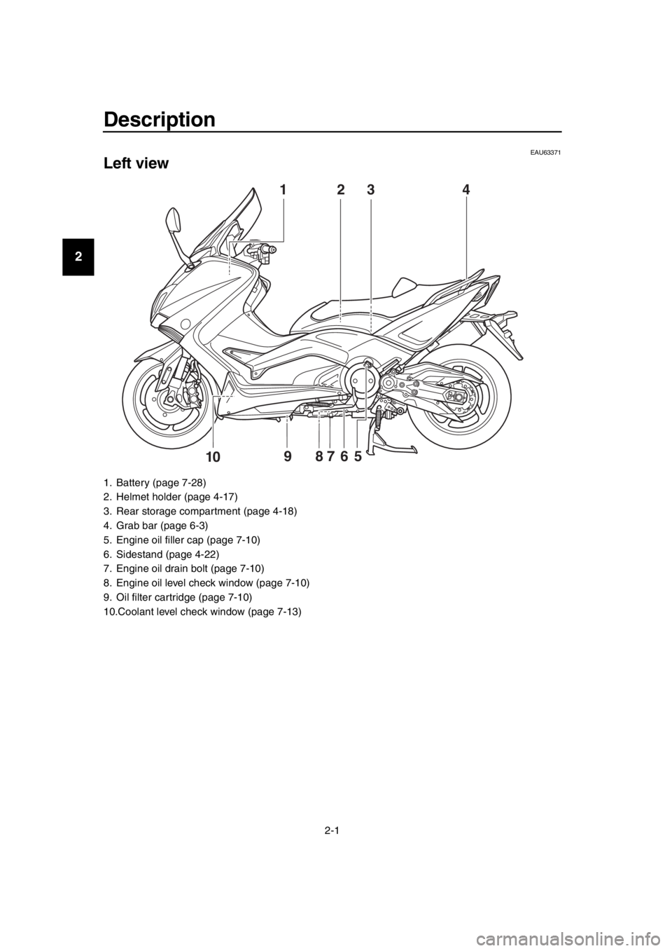
EAU63371
Left view
1. Battery (page 7-28)
2. Helmet holder (page 4-17)
3. Rear storage compartment (page 4-18)
4. Grab bar (page 6-3)
5. Engine oil filler cap (page 7-10)
6. Sidestand (page 4-22)
7. Engine oil drain bolt (page 7-10)
8. Engine oil level check window (page 7-10)
9. Oil filter cartridge (page 7-10)
10.Coolant level check window (page 7-13)
3
59 87610
142
2PW-9-E1.book 1 ページ 2015年9月10日 木曜日 午後5時17分
Page 30 of 110
Instrument and control functions
4-5
1
2
3
4
5
6
7
8
9
10
11
12
13
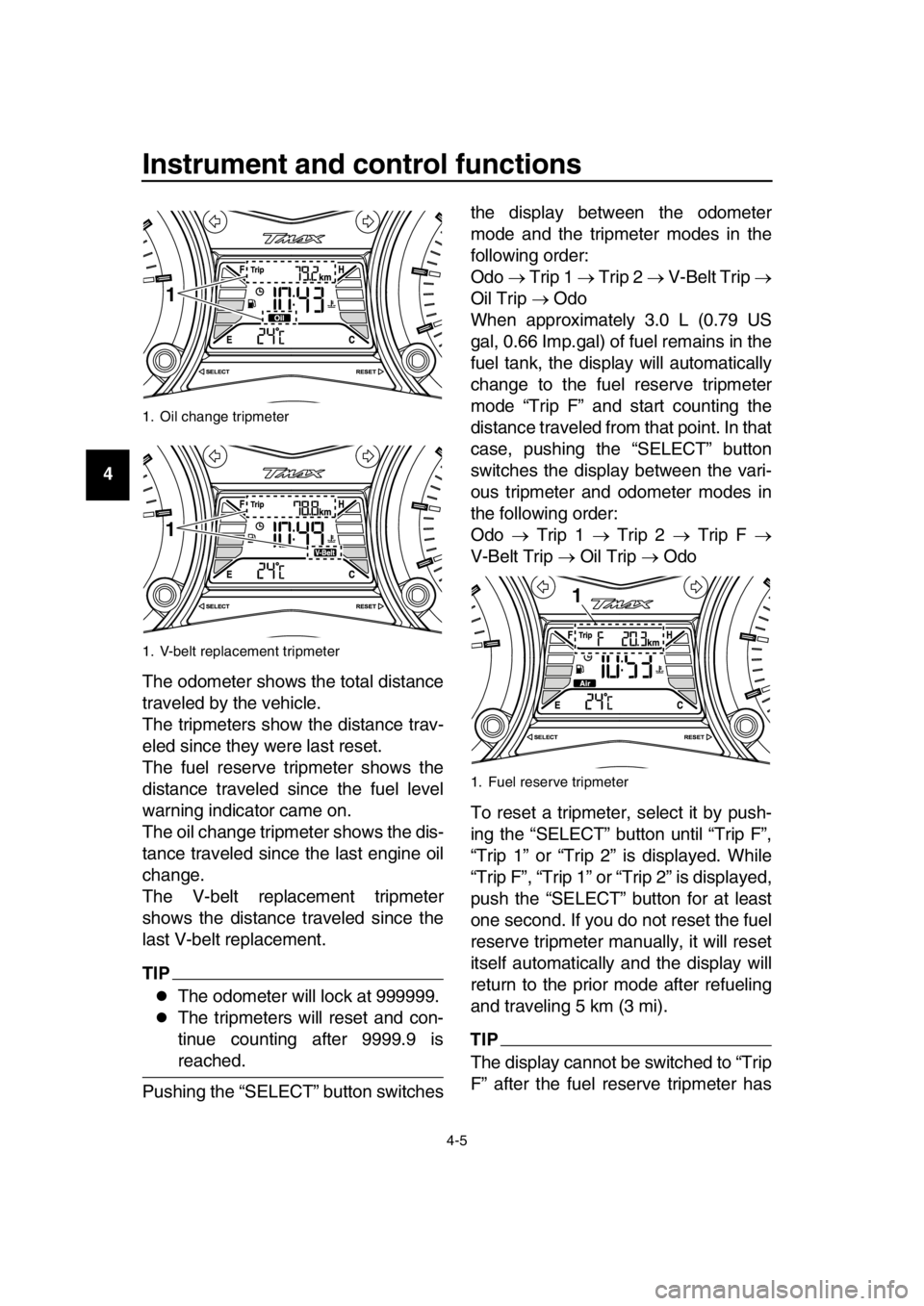
14 The odometer shows the total distance
traveled by the vehicle.
The tripmeters show the distance trav-
eled since they were last reset.
The fuel reserve tripmeter shows the
distance traveled since the fuel level
warning indicator came on.
The oil change tripmeter shows the dis-
tance traveled since the last engine oil
change.
The V-belt replacement tripmeter
shows the distance traveled since the
last V-belt replacement.
TIP
The odometer will lock at 999999.
The tripmeters will reset and con-
tinue counting after 9999.9 is
reached.
Pushing the “SELECT” button switches the display between the odometer
mode and the tripmeter modes in the
following order:
Odo
Trip 1 Trip 2 V-Belt Trip
Oil Trip Odo
When approximately 3.0 L (0.79 US
gal, 0.66 Imp.gal) of fuel remains in the
fuel tank, the display will automatically
change to the fuel reserve tripmeter
mode “Trip F” and start counting the
distance traveled from that point. In that
case, pushing the “SELECT” button
switches the display between the vari-
ous tripmeter and odometer modes in
the following order:
Odo Trip 1 Trip 2 Trip F
V-Belt Trip Oil Trip Odo
To reset a tripmeter, select it by push-
ing the “SELECT” button until “Trip F”,
“Trip 1” or “Trip 2” is displayed. While
“Trip F”, “Trip 1” or “Trip 2” is displayed,
push the “SELECT” button for at least
one second. If you do not reset the fuel
reserve tripmeter manually, it will reset
itself automatically and the display will
return to the prior mode after refueling
and traveling 5 km (3 mi).
TIP
The display cannot be switched to “Trip
F” after the fuel reserve tripmeter has
1. Oil change tripmeter
1. V-belt replacement tripmeter
1
1
1. Fuel reserve tripmeter
1
2PW-9-E1.book 5 ページ 2015年9月10日 木曜日 午後5時17分
Page 31 of 110
Instrument and control functions
4-6
1
2
3
4
5
6
7
8
9
10
11
12
13
14
been reset.
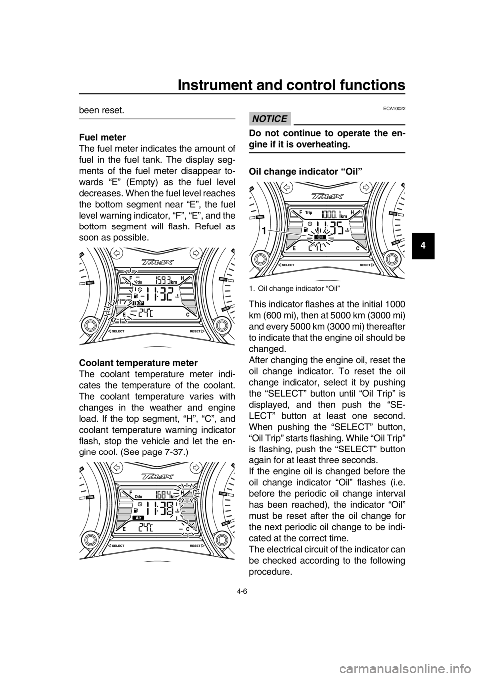
Fuel meter
The fuel meter indicates the amount of
fuel in the fuel tank. The display seg-
ments of the fuel meter disappear to-
wards “E” (Empty) as the fuel level
decreases. When the fuel level reaches
the bottom segment near “E”, the fuel
level warning indicator, “F”, “E”, and the
bottom segment will flash. Refuel as
soon as possible.
Coolant temperature meter
The coolant temperature meter indi-
cates the temperature of the coolant.
The coolant temperature varies with
changes in the weather and engine
load. If the top segment, “H”, “C”, and
coolant temperature warning indicator
flash, stop the vehicle and let the en-
gine cool. (See page 7-37.)NOTICE
ECA10022
Do not continue to operate the en-
gine if it is overheating.
Oil change indicator “Oil”
This indicator flashes at the initial 1000
km (600 mi), then at 5000 km (3000 mi)
and every 5000 km (3000 mi) thereafter
to indicate that the engine oil should be
changed.
After changing the engine oil, reset the
oil change indicator. To reset the oil
change indicator, select it by pushing
the “SELECT” button until “Oil Trip” is
displayed, and then push the “SE-
LECT” button at least one second.
When pushing the “SELECT” button,
“Oil Trip” starts flashing. While “Oil Trip”
is flashing, push the “SELECT” button
again for at least three seconds.
If the engine oil is changed before the
oil change indicator “Oil” flashes (i.e.
before the periodic oil change interval
has been reached), the indicator “Oil”
must be reset after the oil change for
the next periodic oil change to be indi-
cated at the correct time.
The electrical circuit of the indicator can
be checked according to the following
procedure.
1. Oil change indicator “Oil”
1
2PW-9-E1.book 6 ページ 2015年9月10日 木曜日 午後5時17分
Page 50 of 110
5-1
1
2
3
4
5
6
7
8
9
10
11
12
13
14
For your safety – pre-operation checks
EAU63440
Inspect your vehicle each time you use it to make sure the vehicle is in safe oper-
ating condition. Always follow the inspection and maintenance procedures and
schedules described in the Owner’s Manual.
WARNING
EWA11152
Failure to inspect or maintain the vehicle properly increases the possibility
of an accident or equipment damage. Do not operate the vehicle if you find
any problem. If a problem cannot be corrected by the procedures provided
in this manual, have the vehicle inspected by a Yamaha dealer.
Before using this vehicle, check the following points:
ITEM CHECKSPAGE
Fuel Check fuel level in fuel tank.
Refuel if necessary.
Check fuel line for leakage.
Check fuel tank breather hose and overflow hose for
obstructions, cracks or damage, and check hose
connections. 4-15
Engine oil Check oil level in engine.
If necessary, add recommended oil to specified level.
Check vehicle for oil leakage. 7-10
Coolant Check coolant level in reservoir.
If necessary, add recomm
ended coolant to specified
level.
Check cooling system for leakage. 7-13
Front brake Check operation.
If soft or spongy, have Yamaha dealer bleed hydraulic
system.
Check brake pads for wear.
Replace if necessary.
Check fluid level in reservoir.
If necessary, add specified brake fluid to specified level.
Check hydraulic system for leakage. 7-20,
7-22
Rear brake Check operation.
If soft or spongy, have Yamaha dealer bleed hydraulic
system.
Check brake pads for wear.
Replace if necessary.
Check fluid level in reservoir.
If necessary, add specified brake fluid to specified level.
Check hydraulic system for leakage. 7-20,
7-22
Throttle grip Make sure that operation is smooth.
Check throttle grip free play.
If necessary, have Yamaha dealer adjust throttle grip
free play and lubricate cable and grip housing. 7-16,
7-25
2PW-9-E1.book 1 ページ 2015年9月10日 木曜日 午後5時17分
Page 62 of 110
Periodic maintenance and adjustment
7-5
1
2
3
4
5
6
7
8
9
10
11
12
13
14
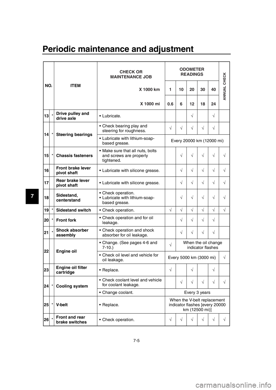
13 *Drive pulley and
drive axle Lubricate.
14 *Steering bearings Check bearing play and
steering for roughness.
Lubricate with lithium-soap- based grease. Every 20000 km (12000 mi)
15 *Chassis fasteners Make sure that all nuts, bolts
and screws are properly
tightened.
16 Front brake lever
pivot shaft Lubricate with silicone grease.
17 Rear brake lever
pivot shaft Lubricate with silicone grease.
18 Sidestand,
centerstand Check operation.
Lubricate with lithium-soap-
based grease.
19 *Sidestand switch Check operation.
20 *Front fork Check operation and for oil
leakage.
21 *Shock absorber
assembly Check operation and shock
absorber for oil leakage.
22 Engine oil Change. (See pages 4-6 and
7-10.) When the oil change
indicator flashes
Check oil level and vehicle for oil leakage. Every 5000 km (3000 mi)
23 Engine oil filter
cartridge Replace.
24 *Cooling system Check coolant level and vehicle
for coolant leakage.
Change coolant. Every 3 years
25 *V- b e l t Replace. When the V-belt replacement
indicator flashes [every 20000 km (12500 mi)]
26 *Front and rear
brake switches Check operation.
NO. ITEM
X 1000 km
CHECK OR
MAINTENANCE JOB
X 1000 mi
ODOMETER READINGS
ANNUAL CHECK
110203040
0.66121824
2PW-9-E1.book 5 ページ 2015年9月10日 木曜日 午後5時17分
Page 63 of 110

Periodic maintenance and adjustment
7-6
1
2
3
4
5
6
7
8
9
10
11
12
13
14
EAU38263
TIP
Engine air filter and V-belt air filters This model’s engine air fi lter is equipped with a disposable oil-coated paper
element, which must not be cleaned wi th compressed air to avoid damaging
it.
The engine air filter element needs to be replaced and the V-belt air filter el- ements need to be serviced more frequently when riding in unusually wet or
dusty areas.
Hydraulic brake service After disassembling the brake master cylinders and calipers, always change the fluid. Regularly check the brake fluid levels and fill the reservoirs
as required.
Every two years replace the internal components of the brake master cylin-
ders and calipers, and change the brake fluid.
Replace the brake hoses every four years and if cracked or damaged.
27 Moving parts and
cables Lubricate.
28 *Throttle grip Check operation.
Check throttle grip free play,
and adjust if necessary.
Lubricate cable and grip housing.
29 *Lights, signals and
switches Check operation.
Adjust headlight beam.
NO. ITEM
X 1000 km
CHECK OR
MAINTENANCE JOB
X 1000 mi
ODOMETER READINGS
ANNUAL CHECK
110203040
0.66121824
2PW-9-E1.book 6 ページ 2015年9月10日 木曜日 午後5時17分
Page 67 of 110
Periodic maintenance and adjustment
7-10
1
2
3
4
5
6
7
8
9
10
11
12
13
14
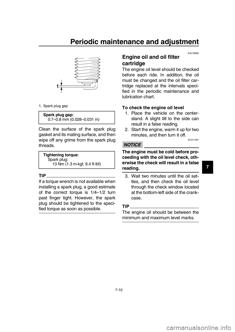
Clean the surface of the spark plug
gasket and its mating surface, and then
wipe off any grime from the spark plug
threads.
TIP
If a torque wrench is not available when
installing a spark plug, a good estimate
of the correct torque is 1/4–1/2 turn
past finger tight. However, the spark
plug should be tightened to the speci-
fied torque as soon as possible.
EAU1985E
Engine oil and oil filter
cartridge
The engine oil level should be checked
before each ride. In addition, the oil
must be changed and the oil filter car-
tridge replaced at the intervals speci-
fied in the periodic maintenance and
lubrication chart.
To check the engine oil level
1. Place the vehicle on the center- stand. A slight tilt to the side can
result in a false reading.
2. Start the engine, warm it up for two minutes, and then turn it off.
NOTICE
ECA11291
The engine must be cold before pro-
ceeding with the oil level check, oth-
erwise the check will result in a false
reading.
3. Wait two minutes until the oil set- tles, and then check the oil level
through the check window located
at the bottom-left side of the crank-
case.
TIP
The engine oil should be between the
minimum and maximum level marks.
1. Spark plug gap
Spark plug gap:0.7–0.8 mm (0.028–0.031 in)
Tightening torque: Spark plug:
13 Nm (1.3 m·kgf, 9.4 ft·lbf)
2PW-9-E1.book 10 ページ 2015年9月10日 木曜日 午後5時17分
Page 68 of 110
Periodic maintenance and adjustment
7-11
1
2
3
4
5
6
7
8
9
10
11
12
13
14 4. If the engine oil is below the mini-
mum level mark, add sufficient oil
of the recommended type to raise
it to the correct level.
To change the engine oil (with or
without oil filter cartridge replace-
ment) 1. Place the vehicle on a level sur- face.
2. Start the engine, warm it up for several minutes, and then turn it
off.
3. Place an oil pan under the engine to collect the used oil.
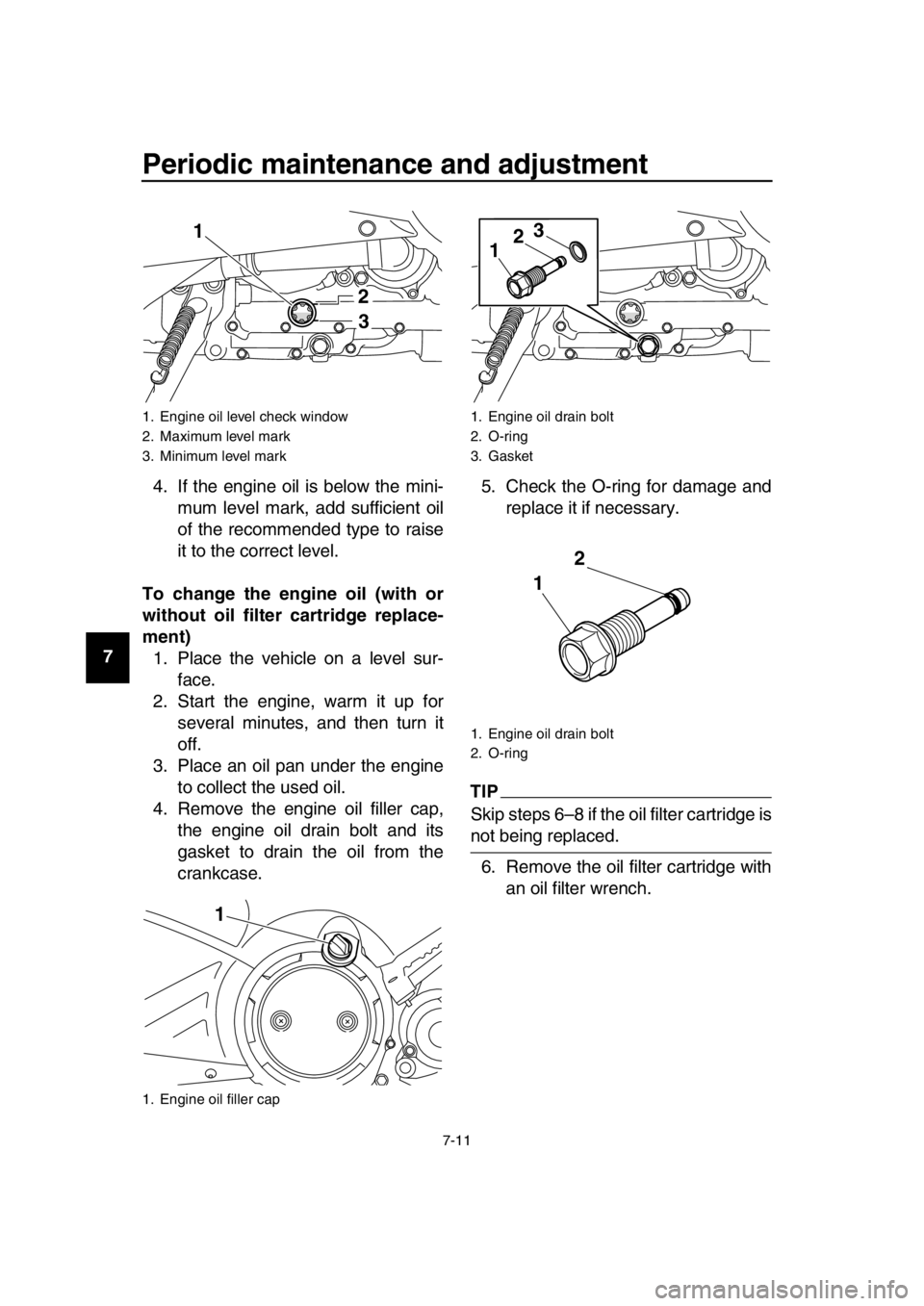
4. Remove the engine oil filler cap, the engine oil drain bolt and its
gasket to drain the oil from the
crankcase. 5. Check the O-ring for damage and
replace it if necessary.
TIP
Skip steps 6–8 if the oil filter cartridge is
not being replaced.
6. Remove the oil filter cartridge with an oil filter wrench.
1. Engine oil level check window
2. Maximum level mark
3. Minimum level mark
1. Engine oil filler cap
1
23
1
1. Engine oil drain bolt
2. O-ring
3. Gasket
1. Engine oil drain bolt
2. O-ring
1 2
3
1 2
2PW-9-E1.book 11 ページ 2015年9月10日 木曜日 午後5時17分
Page 70 of 110
Periodic maintenance and adjustment
7-13
1
2
3
4
5
6
7
8
9
10
11
12
13
14 lubricates the clutch), do not
mix any chemical additives. Do
not use oils with a diesel speci-
fication of “CD” or oils of a high-
er quality than specified. In
addition, do not use oils labeled
“ENERGY CONSERVING II” or
higher.
Make sure that no foreign mate-
rial enters the crankcase.
11. Start the engine, and then let it idle for several minutes while checking
it for oil leakage. If oil is leaking, im-
mediately turn the engine off and
check for the cause.
12. Turn the engine off, and then check the oil level and correct it if
necessary.
13. Reset the oil change indicator. (See page 4-6.)
TIP
If the engine oil is changed before the
oil change indicator comes on (i.e. be-
fore the periodic oil change interval has
been reached), the indicator must be
reset after the oil change for the next
periodic oil change to be indicated at
the correct time.
EAU20071
Coolant
The coolant level should be checked
before each ride. In addition, the cool-
ant must be changed at the intervals
specified in the periodic maintenance
and lubrication chart.
EAU52024To check the coolant level1. Place the vehicle on the center- stand.
TIP
The coolant level must be checked
on a cold engine since the level
varies with engine temperature.
Make sure that the vehicle is posi-
tioned straight up when checking
the coolant level. A slight tilt to the
side can result in a false reading.
2. Check the coolant level through the check window.
TIP
The coolant should be between the
minimum and maximum level marks.
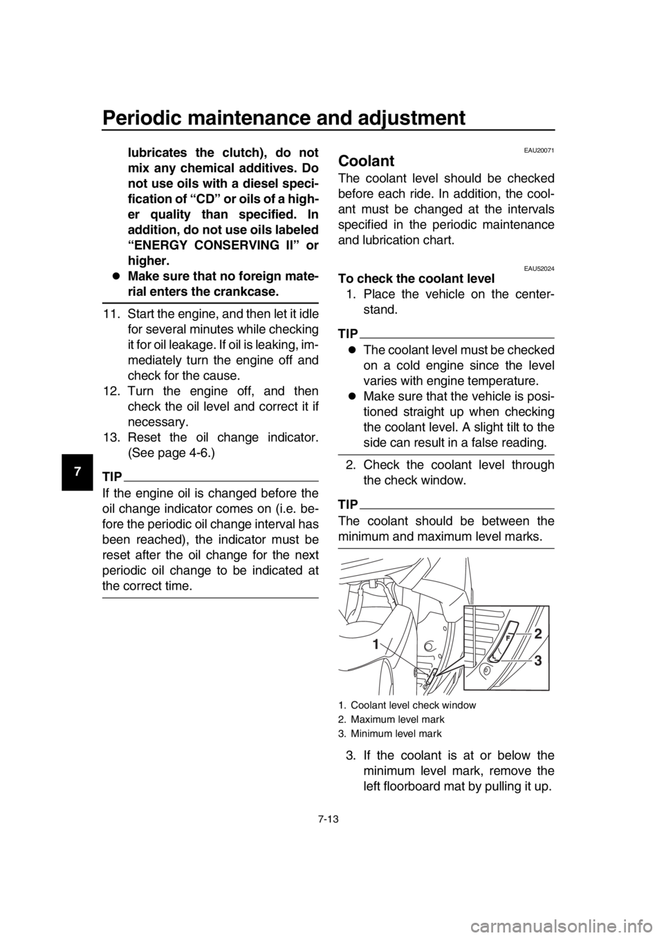
3. If the coolant is at or below the minimum level mark, remove the
left floorboard mat by pulling it up.
1. Coolant level check window
2. Maximum level mark
3. Minimum level mark
12
3
2PW-9-E1.book 13 ページ 2015年9月10日 木曜日 午後5時17分