warning YAMAHA TMAX 2021 Service Manual
[x] Cancel search | Manufacturer: YAMAHA, Model Year: 2021, Model line: TMAX, Model: YAMAHA TMAX 2021Pages: 124, PDF Size: 7.93 MB
Page 99 of 124

Periodic maintenance an d a djustment
8-28
8
EAU23173
Lu bricatin g the front an d rear
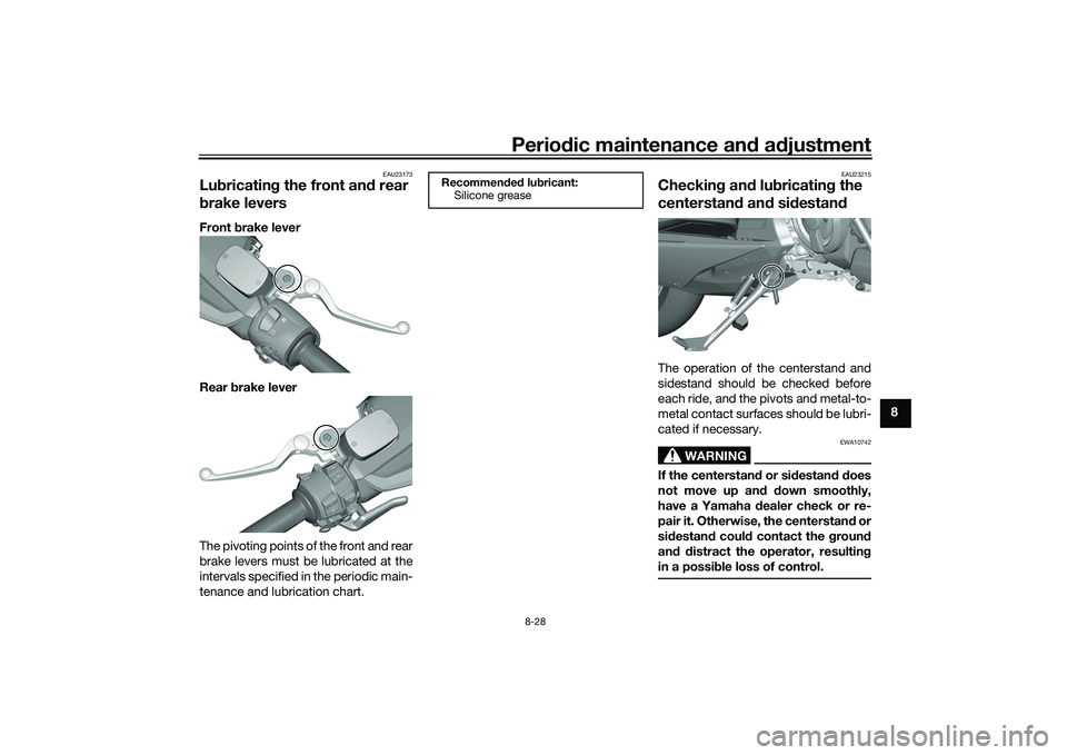
b rake leversFront brake lever
Rear brake lever
The pivoting points of the front and rear
brake levers must be lubricated at the
intervals specified in the periodic main-
tenance and lubrication chart.
EAU23215
Checkin g an d lu bricatin g the
centerstan d an d si destan dThe operation of the centerstand and
sidestand should be checked before
each ride, and the pivots and metal-to-
metal contact surfaces should be lubri-
cated if necessary.
WARNING
EWA10742
If the centerstan d or si destan d d oes
not move up an d d own smoothly,
have a Yamaha dealer check or re-
pair it. Otherwise, the centerstan d or
si destan d coul d contact the g round
an d d istract the operator, resultin g
in a possi ble loss of control.
Recommen ded lu bricant:
Silicone grease
UB3TE1E0.book Page 28 Friday, September 11, 2020 8:48 AM
Page 100 of 124

Periodic maintenance an d a djustment
8-29
8
EAU23273
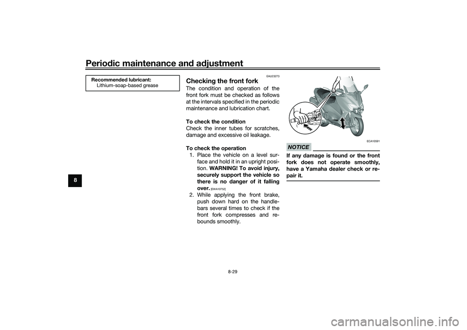
Checkin g the front forkThe condition and operation of the
front fork must be checked as follows
at the intervals specified in the periodic
maintenance and lubrication chart.
To check the con dition
Check the inner tubes for scratches,
damage and excessive oil leakage.
To check the operation 1. Place the vehicle on a level sur- face and hold it in an upright posi-
tion. WARNING! To avoi d injury,
securely support the vehicle so
there is no dan ger of it fallin g
over.
[EWA10752]
2. While applying the front brake, push down hard on the handle-
bars several times to check if the
front fork compresses and re-
bounds smoothly.
NOTICE
ECA10591
If any d amage is foun d or the front
fork does not operate smoothly,
have a Yamaha dealer check or re-
pair it.
Recommen ded lu bricant:
Lithium-soap-based grease
UB3TE1E0.book Page 29 Friday, September 11, 2020 8:48 AM
Page 101 of 124

Periodic maintenance an d a djustment
8-30
8
EAU45512
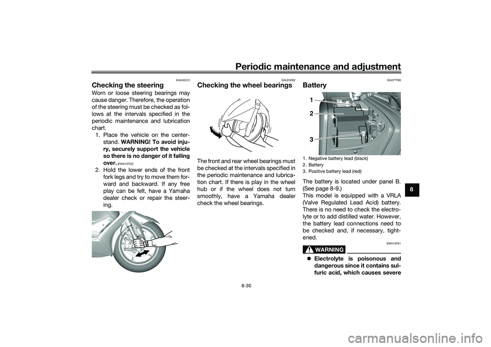
Checkin g the steerin gWorn or loose steering bearings may
cause danger. Therefore, the operation
of the steering must be checked as fol-
lows at the intervals specified in the
periodic maintenance and lubrication
chart.
1. Place the vehicle on the center- stand. WARNING! To avoi d inju-
ry, securely support the vehicle
so there is no d anger of it fallin g
over.
[EWA10752]
2. Hold the lower ends of the front fork legs and try to move them for-
ward and backward. If any free
play can be felt, have a Yamaha
dealer check or repair the steer-
ing.
EAU23292
Checkin g the wheel bearin gsThe front and rear wheel bearings must
be checked at the intervals specified in
the periodic maintenance and lubrica-
tion chart. If there is play in the wheel
hub or if the wheel does not turn
smoothly, have a Yamaha dealer
check the wheel bearings.
EAU77780
BatteryThe battery is located under panel B.
(See page 8-9.)
This model is equipped with a VRLA
(Valve Regulated Lead Acid) battery.
There is no need to check the electro-
lyte or to add distilled water. However,
the battery lead connections need to
be checked and, if necessary, tight-
ened.
WARNING
EWA10761
Electrolyte is poisonous an d
d an gerous since it contains sul-
furic aci d, which causes severe1. Negative battery lead (black)
2. Battery
3. Positive battery lead (red)
1
2
3
UB3TE1E0.book Page 30 Friday, September 11, 2020 8:48 AM
Page 104 of 124

Periodic maintenance an d a djustment
8-33
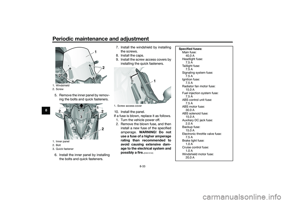
8 5. Remove the inner panel by remov-
ing the bolts and quick fasteners.
6. Install the inner panel by installing the bolts and quick fasteners. 7. Install the windshield by installing
the screws.
8. Install the caps.
9. Install the screw access covers by installing the quick fasteners.
10. Install the panel.
If a fuse is blown, replace it as follows. 1. Turn the vehicle power off.
2. Remove the blown fuse, and then install a new fuse of the specified
amperage. WARNING! Do not
use a fuse of a hi gher ampera ge
ratin g than recommen ded to
avoi d causin g extensive d am-
a g e to the electrical system an d
possi bly a fire.
[EWA15132]
1. Windshield
2. Screw
1. Inner panel
2. Bolt
3. Quick fastener
1
2
2 21 2
2
3 3
2
1. Screw access cover
1
Specified fuses:
Main fuse:
40.0 A
Headlight fuse:
7.5 A
Taillight fuse: 7.5 A
Signaling system fuse: 7.5 A
Ignition fuse:
7.5 A
Radiator fan motor fuse: 15.0 A
Fuel injection system fuse: 7.5 A
ABS control unit fuse:
7.5 A
ABS motor fuse: 30.0 A
ABS solenoid fuse: 15.0 A
Auxiliary DC jack fuse:
2.0 A
Backup fuse: 15.0 A
Electronic throttle valve fuse: 7.5 A
Brake light fuse:
1.0 A
Cruise control fuse: 1.0 A
Windshield motor fuse: 20.0 A
UB3TE1E0.book Page 33 Friday, September 11, 2020 8:48 AM
Page 106 of 124

Periodic maintenance an d a djustment
8-35
8 3. Remove the burnt-out bulb by
pulling it out.
4. Insert a new bulb into the socket, and push the socket in place.
5. Install the license plate unit onto the rear fender.
6. Install the nuts and tighten to the specified torque.
EAU25865
Trou bleshootin gAlthough your Yamaha received a thor-
ough inspection before shipment from
the factory, trouble may occur during
operation. Any problem in the fuel,
compression, or ignition systems, for
example, can cause poor starting and
loss of power.
The following troubleshooting chart
represents a quick and easy procedure
for checking these vital systems your-
self. However, should your vehicle re-
quire any repair, take it to an
authorized Yamaha dealer whose
skilled technicians have the necessary
tools, experience, and know-how to
properly service your Yamaha vehicle.
Be sure to use only genuine Yamaha
replacement parts. Although imitation
parts may look similar to genuine parts,
they are often inferior in quality, have a
shorter service life, and can lead to an
expensive repair bill later on.
WARNING
EWA15142
When checkin g the fuel system, do
not smoke, an d make sure there are
no open flames or sparks in the ar- ea, inclu
din g pilot li ghts from water
heaters or furnaces. Gasoline or
g asoline vapors can i gnite or ex-
plod e, causin g severe injury or prop-
erty damag e.
EAU77992
Smart key system trou bleshootin g
Please check the following items when
the smart key system does not work. Is the smart key turned on? (See
page 3-5.)
Is the smart key battery dis-
charged? (See page 3-6.)
Is the smart key battery installed
correctly? (See page 3-6.)
Is the smart key being used in a lo-
cation with strong radio waves or
other electromagnetic noise? (See
page 3-1.)
Are you using the smart key that is
registered to the vehicle?
Is the vehicle battery discharged?
When the vehicle battery is dis-
charged, the smart key system will
not operate. Please have the vehi-
cle battery charged or replaced.
(See page 8-30.)
1. Collar
2. License plate light bulb
3. License plate light unitTightenin g torque:
License plate light unit nut:
3.8 N·m (0.38 kgf·m, 2.8 lb·ft)
3
2
1
UB3TE1E0.book Page 35 Friday, September 11, 2020 8:48 AM
Page 109 of 124

Periodic maintenance an d a djustment
8-38
8
EAU86420
En gine overheatin g
WARNING
EWAT1041
Do not remove the ra diator cap when the en gine an d ra diator are hot. Scal din g hot flui d an d steam may be
b lown out un der pressure, which coul d cause serious injury. Be sure to wait until the en gine has coole d.
Place a thick rag , like a towel, over the ra diator cap, an d then slowly rotate the cap counterclockwise to the
d etent to allow any resi dual pressure to escape. When the hissin g soun d has stopped , press down on the cap
while turnin g it counterclockwise, an d then remove the cap.TIPIf coolant is not available, tap water can be temporarily used instead, provided that it is changed to the recommended cool-
ant as soon as possible.
Wait until the
engine has cooled.
Check the coolant level in the
reservoir and radiator.
The coolant level
is OK.The coolant level is low.
Check the cooling system
for leakage.
Have a Yamaha dealer checkand repair the cooling system.Add coolant. (See TIP.)
Start the engine. If the engine overheats again,
have a
Yamaha dealer check
and repair the cooling system.
There is
leakage.
There is
no leakage.
UB3TE1E0.book Page 38 Friday, September 11, 2020 8:48 AM
Page 113 of 124

Scooter care and storage
9-2
9
chemicals such as, solvents,
g
asoline, rust removers, b rake
flui d, or antifreeze, etc.
Before washin g
1. Park the vehicle out of direct sun- light and allow it to cool. This will
help avoid water spots.
2. Make sure all caps, covers, elec- trical couplers and connectors are
tightly installed.
3. Cover the muffler end with a plas- tic bag and a strong rubber band.
4. Pre-soak stubborn stains like in- sects or bird droppings with a wet
towel for a few minutes.
5. Remove road grime and oil stains with a quality degreasing agent
and a plastic-bristle brush or
sponge. NOTICE: Do not use
d eg reasin g a gent on areas re-
quirin g lu brication such as
seals, gaskets, an d wheel axles.
Follow pro duct instructions.
[ECA26290]
Washin g
1. Rinse off any degreaser and spray down the vehicle with a garden
hose. Use only enough pressure
to do the job. Avoid spraying wa-
ter directly into the muffler, instru-
ment panel, air inlet, or other inner
areas such as underseat storage
compartments.
2. Wash the vehicle with a quality au- tomotive-type detergent mixed
with cool water and a soft, clean
towel or sponge. Use an old tooth-
brush or plastic-bristle brush for
hard-to-reach places. NOTICE:
Use col d water if the vehicle has
b een exposed to salt. Warm wa-
ter will increase salt’s corrosive
properties.
[ECA26301]
3. For windshield-equipped vehicles: Clean the windshield with a soft
towel or sponge dampened with
water and a pH neutral detergent.
If necessary, use a high-quality
windshield cleaner or polish for
motorcycles. NOTICE: Never use
any stron g chemicals to clean
the wind shield. Additionally,
some cleanin g compoun ds for plastic may scratch the win
d-
shiel d, so b e sure to test all
cleanin g pro ducts before gen-
eral application.
[ECA26310]
4. Rinse off thoroughly with clean water. Be sure to remove all deter-
gent residues, as they can be
harmful to plastic parts.
After washin g
1. Dry the vehicle with a chamois or absorbent towel, preferably mi-
crofiber terrycloth.
2. For drive chain-equipped models: Dry and then lubricate the drive
chain to prevent rust.
3. Use a chrome polish to shine chrome, aluminum, and stainless
steel parts. Often the thermally in-
duced discoloring of stainless
steel exhaust systems can be re-
moved through polishing.
4. Apply a corrosion protection spray on all metal parts including
chrome or nickel-plated surfaces.
WARNING! Do not apply sili- cone or oil spray to seats, han d
g rips, ru bber foot pe gs or tire
trea ds. Otherwise these parts
UB3TE1E0.book Page 2 Friday, September 11, 2020 8:48 AM
Page 114 of 124
![YAMAHA TMAX 2021 Service Manual Scooter care and stora ge
9-3
9 will
become slippery, which
coul d cause loss of control.
Thorou ghly clean the surfaces
of these parts before operatin g
the vehicle.
[EWA20650]
5. Treat rubber, vi YAMAHA TMAX 2021 Service Manual Scooter care and stora ge
9-3
9 will
become slippery, which
coul d cause loss of control.
Thorou ghly clean the surfaces
of these parts before operatin g
the vehicle.
[EWA20650]
5. Treat rubber, vi](/img/51/51438/w960_51438-113.png)
Scooter care and stora ge
9-3
9 will
become slippery, which
coul d cause loss of control.
Thorou ghly clean the surfaces
of these parts before operatin g
the vehicle.
[EWA20650]
5. Treat rubber, vinyl, and unpainted plastic parts with a suitable care
product.
6. Touch up minor paint damage caused by stones, etc.
7. Wax all painted surfaces using a non-abrasive wax or use a detail
spray for motorcycles.
8. When finished cleaning, start the engine and let it idle for several
minutes to help dry any remaining
moisture.
9. If the headlight lens has fogged up, start the engine and turn on
the headlight to help remove the
moisture.
10. Let the vehicle dry completely be- fore storing or covering it.NOTICE
ECA26320
Do not apply wax to ru bber or
unpainte d plastic parts.
Do not use a brasive polishin g
compoun ds as they will wear
away the paint.
Apply sprays an d wax sparin gly.
Wipe off excess afterwar ds.
WARNING
EWA20660
Contaminants left on the b rakes or
tires can cause loss of control. Make sure there is no lu bricant
or wax on the brakes or tires.
If necessary, wash the tires with
warm water an d a mil d d eter-
g ent.
If necessary, clean the brake
d iscs an d pad s with brake
cleaner or acetone.
Before ri din g at hi gher spee ds,
test the vehicle’s b raking per-
formance an d cornerin g b ehav-
ior.
EAU83472
Stora geAlways store the vehicle in a cool, dry
place. If necessary, protect it against
dust with a porous cover. Be sure the
engine and the exhaust system are
cool before covering the vehicle. If the
vehicle often sits for weeks at a time
between uses, the use of a quality fuel
stabilizer is recommended after each
fill-up.NOTICE
ECA21170
Storin g the vehicle in a poorly
ventilate d room or coverin g it
with a tarp, while it is still wet,
will allow water an d humi dity to
seep in an d cause rust.
To prevent corrosion, avoi d
d amp cellars, sta bles (b ecause
of the presence of ammonia)
an d areas where stron g chemi-
cals are store d.Lon g term stora ge
Before storing the vehicle long term (60
days or more):
UB3TE1E0.book Page 3 Friday, September 11, 2020 8:48 AM
Page 115 of 124

Scooter care and storage
9-4
9
1. Make all necessary repairs and
perform any outstanding mainte-
nance.
2. Follow all instructions in the Care section of this chapter.
3. Fill up the fuel tank, adding fuel stabilizer according to product in-
structions. Run the engine for 5
minutes to distribute treated fuel
through the fuel system.
4. For vehicles equipped with a fuel cock: Turn the fuel cock lever to
the off position.
5. For vehicles with a carburetor: To prevent fuel deposits from build-
ing up, drain the fuel in the carbu-
retor float chamber into a clean
container. Retighten the drain bolt
and pour the fuel back into the fuel
tank.
6. Use a quality engine fogging oil according to product instructions
to protect internal engine compo-
nents from corrosion. If engine
fogging oil is not available, per-
form the following steps for each
cylinder:a. Remove the spark plug cap and spark plug. b. Pour a teaspoonful of engine
oil into the spark plug bore.
c. Install the spark plug cap onto the spark plug, and then place
the spark plug on the cylinder
head so that the electrodes are
grounded. (This will limit spark-
ing during the next step.)
d. Turn the engine over several times with the starter. (This will
coat the cylinder wall with oil.)
WARNING! To prevent dam-
a g e or injury from sparkin g,
make sure to groun d the
spark plu g electro des while
turnin g the en gine over.
[EWA10952]
e. Remove the spark plug cap
from the spark plug, and then
install the spark plug and the
spark plug cap.
7. Lubricate all control cables, piv- ots, levers and pedals, as well as
the sidestand and centerstand (if
equipped).
8. Check and correct the tire air pressure, and then lift the vehicle
so that all wheels are off the
ground. Otherwise, turn the wheels a little once a month in or-
der to prevent the tires from be-
coming degraded in one spot.
9. Cover the muffler outlet with a plastic bag to prevent moisture
from entering it.
10. Remove the battery and fully charge it, or attach a maintenance
charger to keep the battery opti-
mally charged. NOTICE: Confirm
that the battery an d its char ger
are compati ble. Do not char ge a
VRLA battery with a convention-
al char ger.
[ECA26330]
TIP If the battery will be removed,
charge it once a month and store
it in a temperate location between
0-30 °C (32-90 °F).
See page 8-30 for more informa-
tion on charging and storing the
battery.
UB3TE1E0.book Page 4 Friday, September 11, 2020 8:48 AM
Page 121 of 124

12-1
12
Index
AABS warning light ................................... 5-3
Acceleration and deceleration ................ 7-3
Air filter element and check hose,
replacing and cleaning ....................... 8-17
Air filter element, V-belt ........................ 8-18
Anti-lock brake system (ABS)............... 5-19
Auxiliary DC jack .................................. 5-26BBattery .................................................. 8-30
Brake fluid, changing............................ 8-26
Brake fluid level, checking.................... 8-25
Brake lever, front .................................. 5-17
Brake lever, rear ................................... 5-18
Brake levers, lubricating ....................... 8-28
Braking ................................................... 7-3CCables, checking and lubricating ......... 8-27
Canister ................................................ 8-12
Care ........................................................ 9-1
Catalytic converter ............................... 5-22
Centerstand and sidestand, checking and lubricating ................................... 8-28
Coolant ................................................. 8-15
Cruise control indicator lights................. 5-3
Cruise control switches .......................... 5-2
Cruise control system............................. 4-1DData recording, vehicle......................... 11-2
Diagnostic connector ........................... 11-2
Dimmer/Pass switch............................... 5-1
D-mode (drive mode).............................. 4-3
Drive belt .............................................. 8-26
Drive mode switch .................................. 5-2
EEmergency mode ................................. 8-39
Engine break-in ...................................... 7-1
Engine idling speed, checking ............. 8-18
Engine oil and oil filter cartridge........... 8-12
Engine overheating .............................. 8-38
Engine serial number ........................... 11-1
Engine stop switch................................. 5-2FFront and rear brake lever free play, checking ............................................ 8-22
Front and rear brake pads, checking ... 8-24
Front fork, checking ............................. 8-29
Fuel ...................................................... 5-20
Fuel consumption, tips for reducing ...... 7-4
Fuel tank cap........................................ 5-20
Fuel tank overflow hose ....................... 5-22
Fuses, replacing ................................... 8-32HHandlebar switches ............................... 5-1
Hazard switch ........................................ 5-2
High beam indicator light ....................... 5-3
Horn switch ............................................ 5-1
How to lock the centerstand ................ 3-10
How to lock the steering ........................ 3-9IIdentification numbers ......................... 11-1
Ignition circuit cut-off system .............. 5-28
Indicator lights and warning lights ......... 5-2KKey, handling of smart and mechanical key ....................................................... 3-3LLicense plate light bulb, replacing ....... 8-34
MMaintenance and lubrication, periodic ... 8-5
Maintenance, emission control system .................................................. 8-3
Malfunction indicator light (MIL) ............. 5-3
Matte color, caution................................ 9-1
Menu switch ........................................... 5-2
Model label ........................................... 11-1
Multi-function display ............................. 5-5OOperating range of the smart key system .................................................. 3-2PPanels, removing and installing .............. 8-9
Parking.................................................... 7-4
Parking mode ....................................... 3-13
Part locations.......................................... 2-1
Powering off the vehicle ......................... 3-8
Powering on the vehicle ......................... 3-7
Power on/Starter switch ......................... 5-2RRear brake lock cable, adjusting .......... 8-23
Rear brake lock, checking .................... 8-23
Rear brake lock lever ............................ 5-18
Rear view mirrors .................................. 5-24SSafe-riding points ................................... 1-5
Safety information................................... 1-1
Select switch .......................................... 5-2
Shock absorber assembly .................... 5-25
Sidestand.............................................. 5-27
Smart key................................................ 3-5
Smart key battery, replacing................... 3-6
Smart key system ................................... 3-1
UB3TE1E0.book Page 1 Friday, September 11, 2020 8:48 AM