YAMAHA VX110 2005 Service Manual
Manufacturer: YAMAHA, Model Year: 2005, Model line: VX110, Model: YAMAHA VX110 2005Pages: 347, PDF Size: 14.17 MB
Page 251 of 347

7-24
E
–+ELECIGNITION SYSTEM
THROTTLE POSITION SENSOR
1. Measure:
Throttle position sensor output voltage
Out of specification →
Replace the
throttle body assembly.
Checking steps:
CAUTION:
Do not loosen the throttle stop screw nut
and do not turn the throttle stop screw.
Connect a computer to the watercraft and
use the Yamaha Diagnostic System to
display the “throttle position sensor 1 out-
put voltage”, “throttle valve opening
angle”, and “throttle position sensor 2
output voltage”.
Release the throttle lever to the fully
closed position.
Check the output voltage of throttle posi-
tion sensor 1 and the throttle valve open-
ing angle.
1Throttle position sensor 1
2Throttle position sensor 2
ÈThrottle position sensor output voltage
ÉThrottle valve opening angle
ÊFully closed
ËFully open
NOTE:
The actual throttle position sensor output
voltage and throttle valve opening angle
may vary according to environmental condi-
tions.
Throttle position sensor 1 output
voltage with throttle lever fully
closed:
0.45–0.95 V (reference data)
Throttle valve opening angle with
throttle lever fully closed:
–1.1–9.4° (reference data)
2 ± 0.1 V
0.5 ± 0.05 V 4.65
± 0.05 V
(4.5 V)
(10˚)
É
ÊË È1 2
ProCarManuals.com
Page 252 of 347

7-25
E
–+ELECIGNITION SYSTEM
Squeeze the throttle lever to the fully
open position and hold it.
Check the output voltage of throttle posi-
tion sensor 2 and the throttle valve open-
ing angle.
Throttle position sensor 2 output
voltage with throttle lever fully
open:
4.60–4.70 V
Throttle valve opening angle with
throttle lever fully open:
above 80° (reference data)
Release the throttle lever from the fully
open position to the fully closed position
slowly and check the output voltage of
throttle position sensor 2 and the throttle
valve opening angle.
Hold the throttle lever when the output
voltage of throttle position sensor 2 is
below 4.5 V and the throttle valve open-
ing angle is above 10°.
Calculate the difference of the output
voltage of throttle position sensor 1 and
the output voltage of throttle position sen-
sor 2.
Throttle position sensor 2 output
voltage – throttle position sensor
1 output voltage = 1.9–2.1 V
Example:
If the output voltage of throttle position sen-
sor 1 is 2.5 V and the output voltage of
throttle position sensor 2 is 4.5 V, then
4.5 – 2.5 = 2.0 V
Operate the throttle lever and check that
the output voltage of throttle position sen-
sors 1 and 2 changes continuously.
NOTE:
The maximum output voltage of throttle
position sensor 2 is 4.65 ±
0.05 V at the half
open position.
ProCarManuals.com
Page 253 of 347

7-26
E
–+ELECIGNITION SYSTEM
ACCELERATOR POSITION SENSOR
1. Measure:
Accelerator position sensor output volt-
age
Out of specification →
Replace the
accelerator position sensor.
Checking steps:
Connect a computer to the watercraft and
use the Yamaha Diagnostic System to
display the “accelerator position sensor
1” and “accelerator position sensor 2”.
Release the throttle lever to the fully
closed position.
Check that the accelerator position sen-
sor 1 and 2 output voltage.
NOTE:
The actual accelerator position sensor out-
put voltage and throttle valve opening angle
may vary according to environmental condi-
tions.
Accelerator position sensor 1
output voltage at throttle lever
fully closed position:
0.50–0.90 V
Accelerator position sensor 2
output voltage at throttle lever
fully closed position:
0.35–1.05 V
Throttle valve opening angle at
throttle lever fully closed
position:
2.7–4.8°
Squeeze the throttle lever to the fully
open position and hold it.
Check that the accelerator position sen-
sor 1 and 2 output voltage.
ProCarManuals.com
Page 254 of 347

7-27
E
–+ELEC
Accelerator position sensor 1
output voltage at throttle lever
fully opened position:
3.75–4.35 V
Accelerator position sensor 2
output voltage at throttle lever
fully opened position:
3.50–4.50 V
Throttle valve opening angle at
throttle lever fully opened
position:
above 61°
Calculate the difference of the accelera-
tor position sensor 1 output voltage and
accelerator position sensor 2 output volt-
age at fully opened position.
Accelerator position sensor 1
output voltage – Accelerator
position sensor 2 output voltage
at fully opened position = below
0.75 V
Example:
If accelerator position sensor 1 output volt-
age is 4.009 V and accelerator position sen-
sor 2 output voltage is 3.896 V, then 4.009
– 3.896 = 0.113 V
Operate the throttle lever, and check that
the accelerator position sensor 1 and 2
output voltage changes continuously.
IGNITION SYSTEM
ProCarManuals.com
Page 255 of 347

7-28
E
–+ELEC
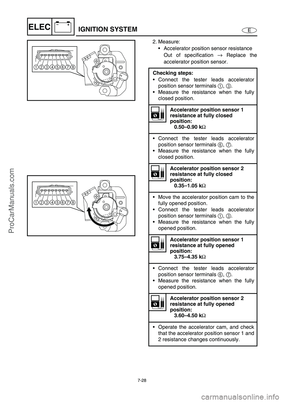
2. Measure:
• Accelerator position sensor resistance
Out of specification →
Replace the
accelerator position sensor.
Checking steps:
Connect the tester leads accelerator
position sensor terminals 1
, 3
.
Measure the resistance when the fully
closed position.
Accelerator position sensor 1
resistance at fully closed
position:
0.50–0.90 kΩ
Connect the tester leads accelerator
position sensor terminals 6
, 7
.
Measure the resistance when the fully
closed position.
Accelerator position sensor 2
resistance at fully closed
position:
0.35–1.05 kΩ
Move the accelerator position cam to the
fully opened position.
Connect the tester leads accelerator
position sensor terminals 1
, 3
.
Measure the resistance when the fully
opened position.
Accelerator position sensor 1
resistance at fully opened
position:
3.75–4.35 kΩ
Connect the tester leads accelerator
position sensor terminals 6
, 7
.
Measure the resistance when the fully
opened position.
Accelerator position sensor 2
resistance at fully opened
position:
3.60–4.50 kΩ
Operate the accelerator cam, and check
that the accelerator position sensor 1 and
2 resistance changes continuously.
14
5678 3 2
14
5678 3 2
IGNITION SYSTEM
ProCarManuals.com
Page 256 of 347

7-29
E
–+ELEC
CAM POSITION SENSOR
1. Measure:
Cam position sensor output voltage
Out of specification →
Replace.
NOTE:
The cam position sensor consists of two indi-
vidual sensors as shown in the illustration:
sensor 1 1
and sensor 2 2
.
To measure the output voltage, pass a
screwdriver under the cam position sensor at
measuring points A, B (center), and C in this
order.
When operating the Yamaha Diagnostic Sys-
tem, electric power is supplied to the cam
position sensor.
Test harness (3 pins):
New: YB-06877
Current: YB-06777
Test harness HM090-3 (3 pins):
New: 90890-06877
Current: 90890-06777
Cam position sensor output
voltage:
Green/orange (G/O) –
Black/orange (B/O)
Position Voltage (V)
A More than 4.8
B Less than 0.8
C More than 4.8
Measurement steps:
Remove the cam position sensor.
Connect the test harness to the cam
position sensor.
Operate the Yamaha Diagnostic System.
Pass a screwdriver under the cam posi-
tion sensor in the direction shown and
measure the output voltage.
1
2
A
B
C
IGNITION SYSTEM
ProCarManuals.com
Page 257 of 347

7-30
E
–+ELEC
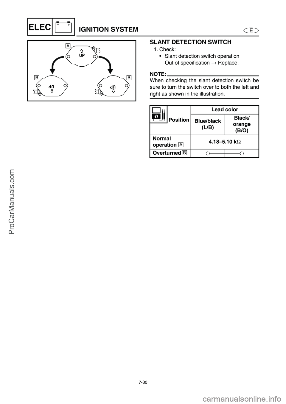
SLANT DETECTION SWITCH
1. Check:
Slant detection switch operation
Out of specification →
Replace.
NOTE:
When checking the slant detection switch be
sure to turn the switch over to both the left and
right as shown in the illustration.
PositionLead color
Blue/black
(L/B)Black/
orange
(B/O)
Normal
operation
È 4.18–5.10 k
Ω
Overturned
É
UP
UPUP
È
É É
IGNITION SYSTEM
ProCarManuals.com
Page 258 of 347

7-31
E
–+ELECFUEL CONTROL SYSTEM
FUEL CONTROL SYSTEM
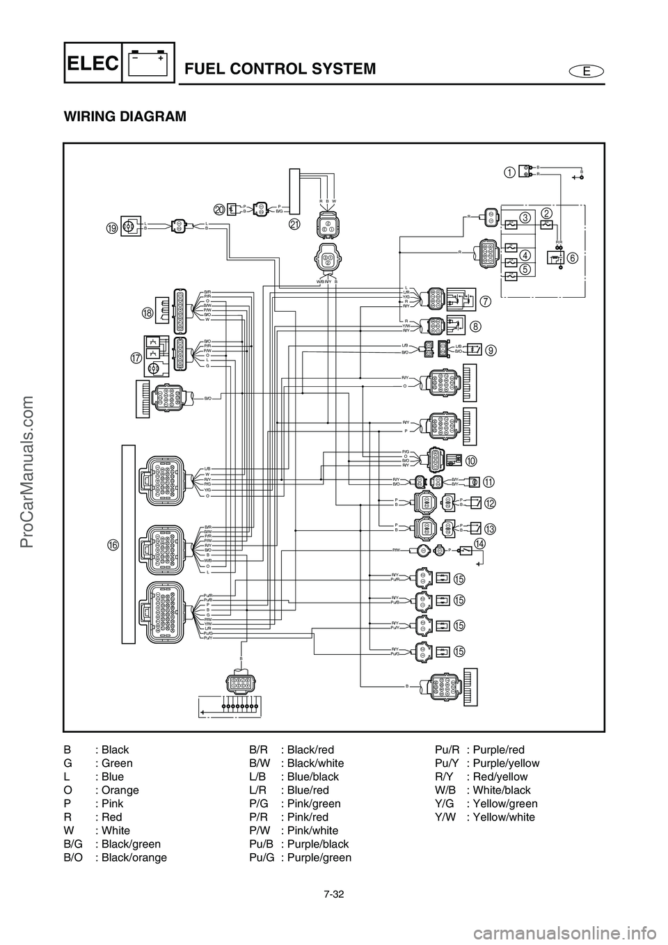
WIRING DIAGRAM
10A
10A
3A
30A20A
RR
BBR
B/W
B/O
B/O
B/R
P/R
P/R
P/W
P/W
B/O
L/B
B/WB/R
B/O
P/RP/W
G
O
W
O
OLG
WR/YP/GY/G
B
OL
PB
Pu/RPu/B
Pu/GPu/Y
P/W
R/Y
W/B
Y/WL/R
B
BBP
P
P
BBP
R/Y
B/OL/BB/OL/B
P/G
P/W
B/O
B/O
B/YB/YR/Y
R/Y
R/Y
R/YPu/G
Pu/Y
Pu/B
Pu/RR/Y
R/Y
R/Y
R/Y
R/YY/W
Y/GL/R
O
P
P
O
R
R
L
R
R
B
BLBL
B
B/GPPB
W/BR/YB RW
9 87
E
E E E FGH I3
4
56 2 1
0
A
B
C
D J
K
1Battery
2Fuse (30 A)
3Fuse (20 A)
4Fuse (10 A)
5Fuse (10 A)
6Starter relay
7Main and fuel pump relay
8Electronic control throttle valve
relay9Slant detection switch
0Sensor assembly
(intake air pressure and intake
air temperature)
AEngine temperature sensor
BThermoswitch (engine)
CThermoswitch (exhaust)
DOil pressure switch
EFuel injectorFECM
GThrottle body assembly
HAccelerator position sensor
IElectric fuel pump
JFuel sender
KMultifunction meter
ProCarManuals.com
Page 259 of 347

7-32
E
–+ELECFUEL CONTROL SYSTEM
WIRING DIAGRAM
10A
10A
3A
30A20A
RR
BBR
B/W
B/O
B/O
B/R
P/R
P/R
P/W
P/W
B/O
L/B
B/WB/R
B/O
P/RP/W
G
O
W
O
OLG
WR/YP/GY/G
B
OL
PB
Pu/RPu/B
Pu/GPu/Y
P/W
R/Y
W/B
Y/WL/R
B
BBP
P
P
BBP
R/Y
B/OL/BB/OL/B
P/G
P/W
B/O
B/O
B/YB/YR/Y
R/Y
R/Y
R/YPu/G
Pu/Y
Pu/B
Pu/RR/Y
R/Y
R/Y
R/Y
R/YY/W
Y/GL/R
O
P
P
O
R
R
L
R
R
B
BLBL
B
B/GPPB
W/BR/YB RW
9 87
E
E E E FGH I3
4
56 2 1
0
A
B
C
D J
K
B: Black
G: Green
L: Blue
O : Orange
P: Pink
R: Red
W: White
B/G : Black/green
B/O : Black/orangeB/R : Black/red
B/W : Black/white
L/B : Blue/black
L/R : Blue/red
P/G : Pink/green
P/R : Pink/red
P/W : Pink/white
Pu/B : Purple/black
Pu/G : Purple/greenPu/R : Purple/red
Pu/Y : Purple/yellow
R/Y : Red/yellow
W/B : White/black
Y/G : Yellow/green
Y/W : Yellow/white
ProCarManuals.com
Page 260 of 347

7-33
E
–+ELECFUEL CONTROL SYSTEM
ELECTRIC FUEL PUMP
1. Check:
Fuel pump operating sound
Fuel pump does not sound →
Measure
the fuel pressure.
Refer to “FUEL INJECTION SYSTEM”
in Chapter 4.
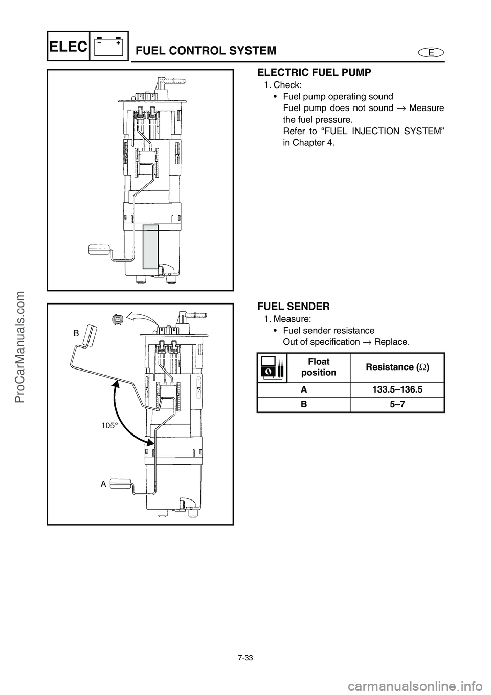
FUEL SENDER
1. Measure:
Fuel sender resistance
Out of specification →
Replace.
Float
positionResistance (
Ω)
A 133.5–136.5
B5–7
ProCarManuals.com