YAMAHA VX110 2005 Service Manual
Manufacturer: YAMAHA, Model Year: 2005, Model line: VX110, Model: YAMAHA VX110 2005Pages: 347, PDF Size: 14.17 MB
Page 221 of 347

6-22
E
JET
PUMPBEARING HOUSING
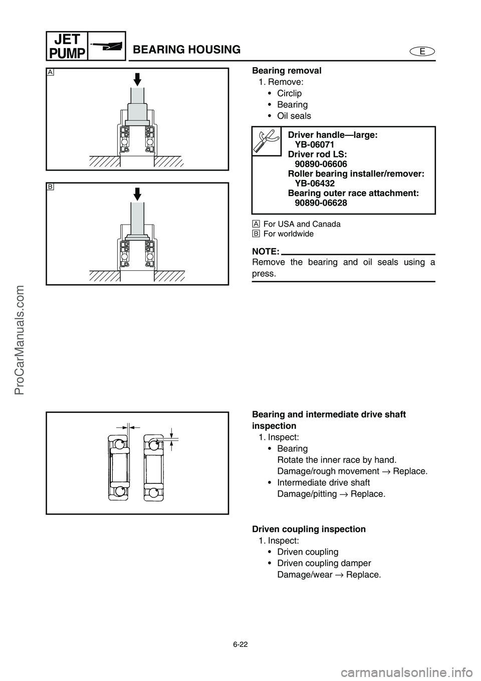
Bearing removal
1. Remove:
Circlip
Bearing
Oil seals
ÈFor USA and Canada
ÉFor worldwide
NOTE:
Remove the bearing and oil seals using a
press.
Driver handle—large:
YB-06071
Driver rod LS:
90890-06606
Roller bearing installer/remover:
YB-06432
Bearing outer race attachment:
90890-06628
È
É
Bearing and intermediate drive shaft
inspection
1. Inspect:
Bearing
Rotate the inner race by hand.
Damage/rough movement →
Replace.
Intermediate drive shaft
Damage/pitting →
Replace.
Driven coupling inspection
1. Inspect:
Driven coupling
Driven coupling damper
Damage/wear →
Replace.
ProCarManuals.com
Page 222 of 347

6-23
E
JET
PUMPBEARING HOUSING
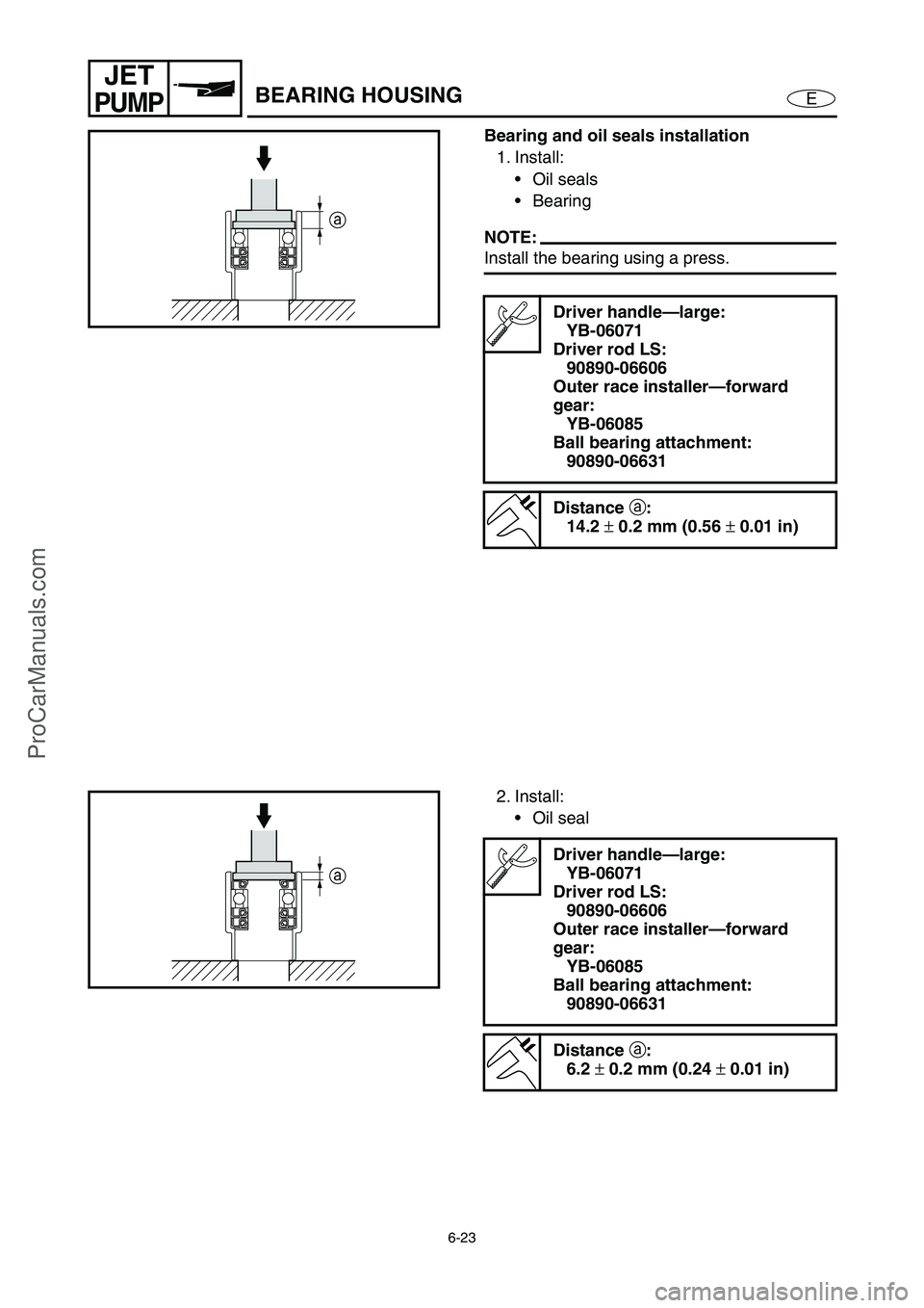
Bearing and oil seals installation
1. Install:
Oil seals
Bearing
NOTE:
Install the bearing using a press.
Driver handle—large:
YB-06071
Driver rod LS:
90890-06606
Outer race installer—forward
gear:
YB-06085
Ball bearing attachment:
90890-06631
Distance
a:
14.2
± 0.2 mm (0.56
± 0.01 in)
a
2. Install:
Oil seal
Driver handle—large:
YB-06071
Driver rod LS:
90890-06606
Outer race installer—forward
gear:
YB-06085
Ball bearing attachment:
90890-06631
Distance
a:
6.2
± 0.2 mm (0.24
± 0.01 in)
a
ProCarManuals.com
Page 223 of 347

6-24
E
JET
PUMPBEARING HOUSING
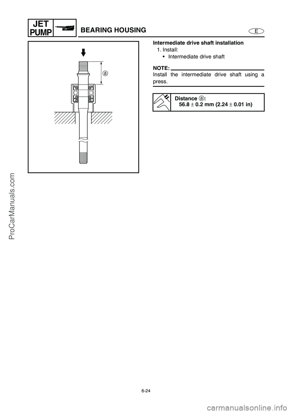
Intermediate drive shaft installation
1. Install:
Intermediate drive shaft
NOTE:
Install the intermediate drive shaft using a
press.
Distance
a:
56.8
± 0.2 mm (2.24
± 0.01 in)
a
ProCarManuals.com
Page 224 of 347

ProCarManuals.com
Page 225 of 347

E
–+ELEC
1
2
3
4
5
6
7
8
9
CHAPTER 7
ELECTRICAL SYSTEM
ELECTRICAL COMPONENTS........................................................................ 7-1
FUSE BOX ....................................................................................................... 7-2
EXPLODED DIAGRAM ............................................................................. 7-2
REMOVAL AND INSTALLATION CHART ................................................ 7-2
ECM AND RECTIFIER/REGULATOR............................................................. 7-7
EXPLODED DIAGRAM ............................................................................. 7-7
REMOVAL AND INSTALLATION CHART ................................................ 7-7
ELECTRICAL ANALYSIS ............................................................................... 7-9
INSPECTION............................................................................................. 7-9
Digital tester ........................................................................................ 7-9
Low resistance measurement ........................................................... 7-10
Peak voltage measurement .............................................................. 7-10
Peak voltage adapter ........................................................................ 7-11
Test harness .................................................................................... 7-11
IGNITION SYSTEM ....................................................................................... 7-12
WIRING DIAGRAM ................................................................................. 7-12
IGNITION SPARK ................................................................................... 7-14
IGNITION SYSTEM PEAK VOLTAGE .................................................... 7-15
BATTERY ................................................................................................ 7-17
FUSE ....................................................................................................... 7-17
SPARK PLUGS ....................................................................................... 7-17
IGNITION COIL ....................................................................................... 7-18
ENGINE STOP SWITCH ......................................................................... 7-18
ENGINE TEMPERATURE SENSOR ...................................................... 7-19
SENSOR ASSEMBLY ............................................................................. 7-19
THERMOSWITCH (ENGINE).................................................................. 7-20
THERMOSWITCH (EXHAUST) .............................................................. 7-21
MAIN AND FUEL PUMP RELAY............................................................. 7-22
ELECTRONIC CONTROL THROTTLE VALVE RELAY ......................... 7-23
THROTTLE POSITION SENSOR ........................................................... 7-24
ACCELERATOR POSITION SENSOR ................................................... 7-26
CAM POSITION SENSOR ...................................................................... 7-29
SLANT DETECTION SWITCH ................................................................ 7-30
ProCarManuals.com
Page 226 of 347

E
–+ELEC
FUEL CONTROL SYSTEM ........................................................................... 7-31
WIRING DIAGRAM ................................................................................. 7-31
ELECTRIC FUEL PUMP ......................................................................... 7-33
FUEL SENDER ....................................................................................... 7-33
FUEL INJECTOR .................................................................................... 7-34
MAIN AND FUEL PUMP RELAY............................................................. 7-34
OIL PRESSURE SWITCH ....................................................................... 7-34
THERMOSWITCH (ENGINE).................................................................. 7-34
THERMOSWITCH (EXHAUST) .............................................................. 7-34
SLANT DETECTION SWITCH ................................................................ 7-34
REMOTE CONTROL UNIT (DELUXE MODEL ONLY) ........................... 7-34
THROTTLE POSITION SENSOR ........................................................... 7-34
ACCELERATOR POSITION SENSOR ................................................... 7-34
STARTING SYSTEM ..................................................................................... 7-35
WIRING DIAGRAM ................................................................................. 7-35
BATTERY ................................................................................................ 7-37
WIRING CONNECTIONS........................................................................ 7-37
FUSES..................................................................................................... 7-37
START SWITCH...................................................................................... 7-37
STARTER RELAY ................................................................................... 7-38
REMOTE CONTROL UNIT (DELUXE MODEL ONLY) ........................... 7-38
THROTTLE POSITION SENSOR ........................................................... 7-38
ACCELERATOR POSITION SENSOR ................................................... 7-38
STARTER MOTOR ........................................................................................ 7-39
EXPLODED DIAGRAM ........................................................................... 7-39
REMOVAL AND INSTALLATION CHART ............................................. 7-39
SERVICE POINTS .................................................................................. 7-41
Armature inspection .......................................................................... 7-41
Brush holder inspection..................................................................... 7-42
Starter motor front cover inspection .................................................. 7-42
CHARGING SYSTEM .................................................................................... 7-43
WIRING DIAGRAM ................................................................................. 7-43
FUSE ....................................................................................................... 7-44
BATTERY ................................................................................................ 7-44
LIGHTING COIL ...................................................................................... 7-44
RECTIFIER/REGULATOR ...................................................................... 7-44
OFF THROTTLE STEERING SYSTEM......................................................... 7-45
WIRING DIAGRAM ................................................................................. 7-45
STEERING SENSOR .............................................................................. 7-47
ECM......................................................................................................... 7-47
PICKUP COIL .......................................................................................... 7-47
THROTTLE POSITION SENSOR ........................................................... 7-47
ACCELERATOR POSITION SENSOR ................................................... 7-47
ProCarManuals.com
Page 227 of 347

E
–+ELEC
INDICATION SYSTEM .................................................................................. 7-48
WIRING DIAGRAM ................................................................................. 7-48
FUSE ....................................................................................................... 7-50
BATTERY ................................................................................................ 7-50
MAIN AND FUEL PUMP RELAY............................................................. 7-50
ECM......................................................................................................... 7-50
ENGINE TEMPERATURE SENSOR ...................................................... 7-50
THERMOSWITCH (ENGINE).................................................................. 7-50
THERMOSWITCH (EXHAUST) .............................................................. 7-50
REMOTE CONTROL UNIT (DELUXE MODEL ONLY) ........................... 7-50
BUZZER .................................................................................................. 7-50
OIL PRESSURE SWITCH ....................................................................... 7-51
MULTIFUNCTION METER...................................................................... 7-51
Multifunction meter ............................................................................ 7-51
MULTIFUNCTION METER REMOVAL ................................................... 7-51
Display function (Sport model only) .................................................. 7-52
Display function (Deluxe model only) ................................................ 7-53
Speedometer display ........................................................................ 7-54
Tachometer display ........................................................................... 7-55
Hour meter display ............................................................................ 7-55
Voltage meter display........................................................................ 7-55
Low oil pressure warning indicator .................................................... 7-55
Fuel level meter display and fuel warning indicator .......................... 7-55
Overheat warning indicator ............................................................... 7-56
Check engine warning indicator ........................................................ 7-56
Diagnostic display ............................................................................. 7-57
REMOTE CONTROL SYSTEM (DELUXE MODEL ONLY) .......................... 7-58
WIRING DIAGRAM ................................................................................. 7-58
REMOTE CONTROL SYSTEM ............................................................... 7-59
Yamaha Security System indicator ................................................... 7-59
Low-rpm mode indicator.................................................................... 7-59
Checking the remote control transmitter ........................................... 7-60
Transmitter registration ..................................................................... 7-62
Replacing of the transmitter battery .................................................. 7-63
ProCarManuals.com
Page 228 of 347

7-1
E
–+ELECELECTRICAL COMPONENTS
ELECTRICAL COMPONENTS
O
N
M
L
K
J
I
H
G
F
E
D
C
B
A
0
91
2
3
4
5
6
7
8
1Thermoswitch (engine)
2Fuse box
3Slant detection switch
4Starter motor
5Engine temperature sensor
6Spark plugs and ignition coils
7Cam position sensor
8Battery
9Speed sensor
0Sensor assembly (intake air
pressure and intake air tem-
perature)AOil pressure switch
BFuel injectors
CThermoswitch (exhaust)
DRectifier/regulator
EECM
FThrottle body assembly
GLighting coil and pickup coil
HEngine stop switch, engine
shut-off switch, and start
switch
ISteering sensor
JBuzzerKAccelerator position sensor
LElectric fuel pump
MFuel sender
NMultifunction meter
ORemote control unit (Deluxe
model only)
ProCarManuals.com
Page 229 of 347

7-2
E
–+ELECFUSE BOX
FUSE BOX
EXPLODED DIAGRAM
REMOVAL AND INSTALLATION CHART
Step Procedure/Part name Q’ty Service points
FUSE BOX REMOVAL
Follow the left “Step” for removal.
1 Nut/washer 2/2
2 Wiring harness 1
NOTE:
Disconnect all couplers.
3 Fuse box 1
4 Fuse box cap 1
5Gasket 1
6Fuse 10
7 Tapping screw 2
8 Washer 2
30
3 10
10
20 30
3 10
10
20
6 × 25 mm
6 × 20 mm
6 × 10 mm
6 × 8 mm
6 × 20 mm
AA
AA
3332 31
(VENT)
22
22 21
21 27
27
27
3029 28
24 23
13
1319 19 2625
173
4
5
6 2 1098 7
7
811
12
15
16
18
1420
1
1
17 N •
m (1.7 kgf • m, 12 ft • Ib)
15 N •
m (1.5 kgf • m, 11 ft • Ib)
36
35
35
34
35
17 N •
m (1.7 kgf • m, 12 ft • Ib)
31
6 × 20 mm
3.9 N • m (0.39 kgf • m, 2.8 ft • Ib)
Not reusable
ProCarManuals.com
Page 230 of 347

7-3
E
–+ELECFUSE BOX
EXPLODED DIAGRAM
Step Procedure/Part name Q’ty Service points
9Bracket 1
10 Rubber mount 1
11 Main and fuel pump relay 1
12 Electronic control throttle valve
relay1
13 Tapping screw 2
14 Slant detection switch 1
15 Bolt 6
16 Fuse box cover 1
17 Nut 6
18 Gasket 1
19 Tapping screw 2
30
3 10
10
20 30
3 10
10
20
6 × 25 mm
6 × 20 mm
6 × 10 mm
6 × 8 mm
6 × 20 mm
AA
AA
3332 31
(VENT)
22
22 21
21 27
27
27
3029 28
24 23
13
1319 19 2625
173
4
5
6 2 1098 7
7
811
12
15
16
18
1420
1
1
17 N •
m (1.7 kgf • m, 12 ft • Ib)
15 N •
m (1.5 kgf • m, 11 ft • Ib)
36
35
35
34
35
17 N •
m (1.7 kgf • m, 12 ft • Ib)
31
6 × 20 mm
3.9 N • m (0.39 kgf • m, 2.8 ft • Ib)
Not reusable
ProCarManuals.com