YAMAHA WR 250F 2001 Notices Demploi (in French)
Manufacturer: YAMAHA, Model Year: 2001, Model line: WR 250F, Model: YAMAHA WR 250F 2001Pages: 686, PDF Size: 62.6 MB
Page 301 of 686
ENG
4 - 17
CARBURATEUR
VERGASER
CARBURATORE
14. Montieren:
lMembran (Luftabschaltven-
til) 1
lFeder 2
lO-Ring 3
lDeckel 4
lSchrauben (Deckel)
5
15. Montieren:
lMembran (Luftabschaltven-
til) 1
lFeder 2
lO-Ring 3
lDeckel 4
lSchrauben (Deckel) 5
HINWEIS:
Die Membran (Beschleunigerpumpe)
mit der Markierung a zur Feder wei-
send einbauen.
16. Montieren:
lDüsennadel 1
lDistanzhülse 2
lFeder 3
lNadelhalterung 4
lGasschieber-Scheibe 5
(am Gasschieber 6)
17. Montieren:
lGasschieber (komplett) 1
lSchraube (Drosselklappen
welle) 2
HINWEIS:
Die Gasschieberhebel-Rollen 3 in
die Aussparungen a des Gasschie-
bers führen.
18. Montieren:
lO-Ring 1
lGasschieberhebel-Gehäu-
sedeckel 2
lSchraube (Gasschieberhe-
bel-Gehäusedeckel) 3 14. Monter:
lMembrane (clapet de coupure
d’air) 1
lRessort (clapet de coupure
d’air) 2
lJoint torique 3
lCouvercle du clapet de coupure
d’air 4
lVis (couvercle du clapet de
coupure d’air) 5
15. Monter:
lDiaphragme (pomge d’accélé-
cation) 1
lRessort 2lJoint torique 3lCouvercle de pompe d’accélé-
cation 4
lVis (couvercle de pompe
d’accélécation) 5
N.B.:
Monter le diaphragme (pompe d’accélé-
ration) en veillant à diriger son repère a
vers le ressort.
16. Monter:
lAiguille 1
lCollerette 2
lRessort 3
lSupport de pointeau 4
lPlaquette de boisseau 5
Sur le boisseau 6.
17. Monter:
lEnsemble boisseau 1
lVis (axe de papillon) 2
N.B.:
Monter les rouleaux 3 du levier de bois-
seau dans les fentes a du boisseau.
18. Monter:
lJoint torique 1
lCouvercle du logement de
levier de boisseau 2
lBoulon (couvercle du logement
de levier de boisseau) 3 14. Installare:
lMembrana (valvola di interru-
zione dell’aria) 1
lMolla (valvola di interruzione
dell’aria) 2
lO-ring 3
lCoperchio della valvola di
interruzione dell’aria 4
lVite (coperchio della valvola di
interruzione dell’aria )
5
15. Installare:
lDiaframma (pompa di circola-
zione) 1
lMolla 2 lO-ring 3lCoperchio pompa di circola-
zione 4
lVite (pompa di circolazione) 5
NOTA:
Installare il diaframma (pompa di circo-
lazione) con il riferimento a rivolto
verso la molla.
16. Installare:
lSpillo del getto 1
lCollarino 2
lMolla 3
lFermaglio spillo 4
lPiastra valvola a farfalla 5
Sulla valvola a farfalla 6.
17. Installare:
lGruppo valvola a farfalla 1
lVite (albero della valvola a far-
falla) 2
NOTA:
Installare i rulli della leva della valvola
3 nelle fenditure a della valvola a far-
falla.
18. Installare:
lO-ring 1
lCoperchio alloggiamento leva
valvola 2
lBullone (coperchio alloggia-
mento leva valvola) 3
Page 302 of 686
4 - 18
ENGCARBURETOR
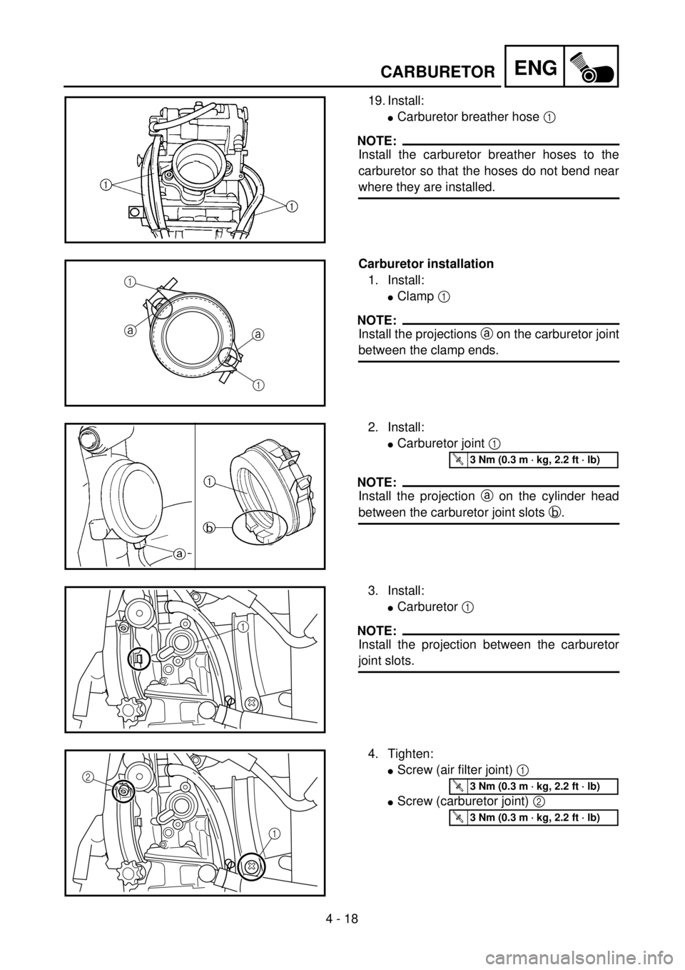
19. Install:
lCarburetor breather hose 1
NOTE:
Install the carburetor breather hoses to the
carburetor so that the hoses do not bend near
where they are installed.
Carburetor installation
1. Install:
lClamp 1
NOTE:
Install the projections a on the carburetor joint
between the clamp ends.
aa
1
1
2. Install:
lCarburetor joint 1
NOTE:
Install the projection a on the cylinder head
between the carburetor joint slots b.
T R..3 Nm (0.3 m · kg, 2.2 ft · lb)
3. Install:
lCarburetor 1
NOTE:
Install the projection between the carburetor
joint slots.
1
4. Tighten:
lScrew (air filter joint) 1
lScrew (carburetor joint) 2
1 2
T R..3 Nm (0.3 m · kg, 2.2 ft · lb)
T R..3 Nm (0.3 m · kg, 2.2 ft · lb)
Page 303 of 686
ENG
4 - 18
CARBURATEUR
VERGASER
CARBURATORE
19. Montieren:
lVergaser-Entlüftungs-
schlauch 1
HINWEIS:
Die Vergaserlüfterschläuche am Ver-
gaser anbringen, so daß die Schläu-
che nicht in der Nähe des Installati-
onsorts gebogen werden.
Vergaser montieren
1. Montieren:
lKlammer 1
HINWEIS:
Die Vorsprünge a an der Vergaser-
verbindung zwischen den Klammer-
nenden einbauen.
2. Montieren:
lVergaseranschluß 1
HINWEIS:
Die Nase a am Zylinder auf die Nut
im Vergaseranschluß ausrichten b.
T R..3 Nm (0,3 m · kg)
3. Montieren:
lVergaser 1
HINWEIS:
Die Nase muß sich zwischen den
Vergaseranschlußschlitzen befinden.
4. Festziehen:
lSchraube (Luftfilteran-
schluß) 1
lSchraube (Vergaseran-
schluß) 2
T R..3 Nm (0,3 m · kg)
T R..3 Nm (0,3 m · kg)
19. Monter:
lDurit de mise à l’air de carbu-
rateur 1
N.B.:
Installer la durit de mise à l’air sur le car-
burateur de sorte qu’il ne se plie pas à
l’endroit où il est installé.
Montage du carburateur
1. Monter:
lBride 1
N.B.:
Insérer les saillies a du raccord de car-
burateur entre les extrémités de bride.
2. Monter:
lRaccord de carburateur 1
N.B.:
Insérer la saillie a sur la culasse entre
les fentes du raccord de carburateur b.
T R..3 Nm (0,3 m · kg, 2,2 ft · lb)
3. Monter:
lCarburateur 1
N.B.:
Monter l’extrémité du support de câble
des gaz entre les fentes du raccord de
carburateur.
4. Serrer:
lVis (raccord de filtre à air) 1
lVis (raccord de carburateur) 2
T R..3 Nm (0,3 m · kg, 2,2 ft · lb)
T R..3 Nm (0,3 m · kg, 2,2 ft · lb)
19. Installare:
lSfiatatoio carburatore 1
NOTA:
Collegare lo sfiatatoio del carburatore al
carburatore stesso in modo tale che i
flessibili non si pieghino in prossimità
del punto in cui vengono montati.
Installazione del carburatore
1. Installare:
lFascetta 1
NOTA:
Installare le sporgenze a sul giunto del
carburatore tra le estremità della fascetta.
2. Installare:
lGiunto del carburatore 1
NOTA:
Installare la sporgenza a sulla testa del
cilindro tra le scanalature sul giunto del
carburatore b.
T R..3 Nm (0,3 m · kg, 2,2 ft · lb)
3. Installare:
lCarburatore 1
NOTA:
Installare la sporgenza tra le fessure del
giunto del carburatore.
4. Serrare:
lVite (giunto filtro dell’aria) 1
lVite (giunto del carburatore)
2
T R..3 Nm (0,3 m · kg, 2,2 ft · lb)
T R..3 Nm (0,3 m · kg, 2,2 ft · lb)
Page 304 of 686

4 - 19
ENG
5. Install:
lThrottle cable cap 1
1
6. Install:
lThrottle cable 1
7. Adjust:
lThrottle grip free play
Refer to “THROTTLE CABLE ADJUST-
MENT” section in the CHAPTER 3.
8. Install:
lThrottle cable cover 1
lScrew (throttle cable cover) 2
NOTE:
Install the throttle cable cover with its pawl a
hung on the carburetor.
12
a
T R..4 Nm (0.4 m · kg, 2.9 ft · lb)
9. Install:
lThrottle position sensor lead coupler 1
lClamp 2
Refer to “CABLE ROUTING DIA-
GRAM” section in the CHAPTER 2.
10. Install:
lClamp 1
Refer to “CABLE ROUTING DIA-
GRAM” section in the CHAPTER 2.
1
CARBURETOR
Page 305 of 686

ENG
4 - 19
CARBURATEUR
VERGASER
CARBURATORE
5. Montieren:
lGasseilzugkappe 1
6. Montieren:
lGaszug 1
7. Einstellen:
lGaszugspiel
Siehe unter “GASZUG-
SPIEL EINSTELLEN” im
KAPITEL 3.
8. Montieren:
lGaszug-Abdeckung 1
lSchraube (gaszug-abdek-
kung) 2
HINWEIS:
Die Gaszug-Abdeckung an der stelle
a ain Vergaser einkaken.
T R..4 Nm (0,4 m · kg)
9. Montieren:
lGaspositionssensor-Leitungs-
koppler 1
lSchlauchschelle 2
Siehe unter “KABEL-
FÜHRUNG” im KAPITEL 2.
10. Montieren:
lSchlauchschelle 1
Siehe unter “KABELFÜH-
RUNG” im KAPITEL 2. 5. Monter:
lCache du logement des câbles
des gaz 1
6. Monter:
lCâble de gaz 1
7. Régler:
lJeu à la poignée des gaz
Se reporter à la section
“REGLAGE DES CABLES
DES GAZ” au CHAPITRE 3.
8. Monter:
lCache du logement des câbles
des gaz 1
lVis (cache du logement des
câbles des gaz) 2
N.B.:
Monter le cache du logement des câbles
des gaz en veillant à ce que son linguet
a soit accroché au carburateur.
T R..4 Nm (0,4 m · kg, 2,9 ft · lb)
9. Monter:
lFiche rapide de fil de capteur
de position de papillon des gaz
1
lBride 2
Se reporter à la section “CHE-
MINEMENT DES CABLES”
au CHAPITRE 2.
10. Monter:
lBride 1
Se reporter à la section “CHE-
MINEMENT DES CABLES”
au CHAPITRE 2.5. Installare:
lTappo del cavo acceleratore 1
6. Installare:
lCavo acceleratore 1
7. Regolare:
lGioco libero manopola
dell’acceleratore
Fare riferimento al paragrafo
“REGOLAZIONE DEL
CAVO DELL’ACCELERA-
TORE” nel CAPITOLO 3.
8. Installare:
lCoperchio cavo acceleratore 1
lVite (coperchio cavo accelera-
tore) 2
NOTA:
Installare il coperchio del cavo con il
nottolino d’arresto a attaccato al carbu-
ratore.
T R..4 Nm (0,4 m · kg, 2,9 ft · lb)
9. Installare:
lAccoppiatore cavo del sensore
di posizione dell’acceleratore
1
lMorsetto 2
Fare riferimento al paragrafo
“SCHEMA DEL PERCORSO
DEI CAVI” nel CAPITOLO 2.
10. Installare:
lMorsetto 1
Fare riferimento al paragrafo
“SCHEMA DEL PERCORSO
DEI CAVI” nel CAPITOLO2.
Page 306 of 686
4 - 20
ENGCAMSHAFTS
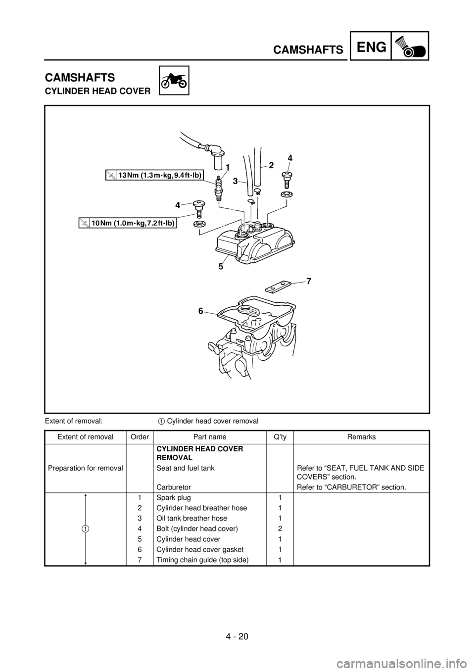
CAMSHAFTS
CYLINDER HEAD COVER
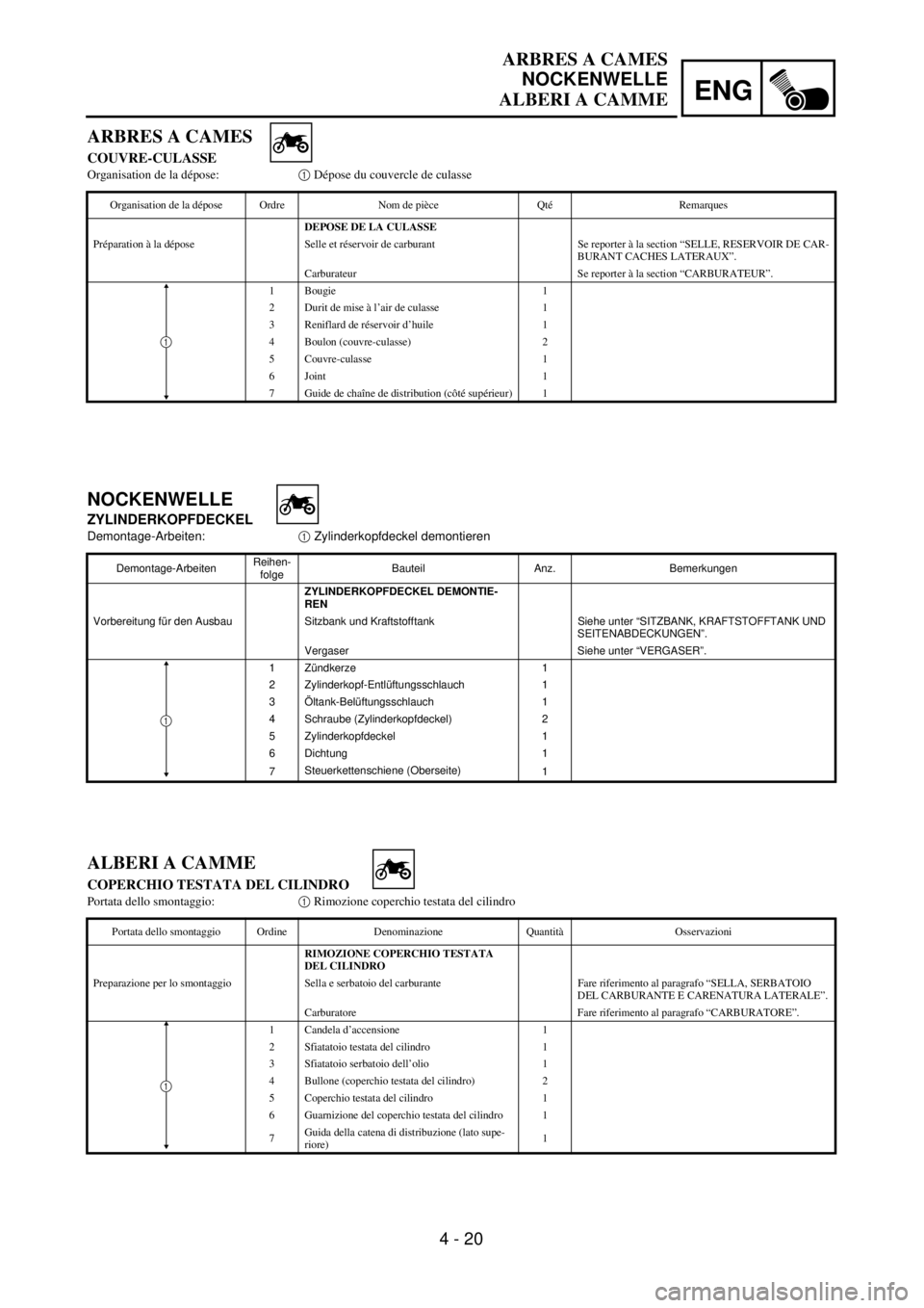
Extent of removal:1 Cylinder head cover removal
Extent of removal Order Part name Q’ty Remarks
CYLINDER HEAD COVER
REMOVAL
Preparation for removal Seat and fuel tank Refer to “SEAT, FUEL TANK AND SIDE
COVERS” section.
Carburetor Refer to “CARBURETOR” section.
1 Spark plug 1
2 Cylinder head breather hose 1
3 Oil tank breather hose 1
4 Bolt (cylinder head cover) 2
5 Cylinder head cover 1
6 Cylinder head cover gasket 1
7Timing chain guide (top side)
1
1
Page 307 of 686
4 - 20
ENG
ARBRES A CAMES
NOCKENWELLE
ALBERI A CAMME
NOCKENWELLE
ZYLINDERKOPFDECKEL
Demontage-Arbeiten:1 Zylinderkopfdeckel demontieren
Demontage-ArbeitenReihen-
folgeBauteil Anz. Bemerkungen
ZYLINDERKOPFDECKEL DEMONTIE-
REN
Vorbereitung für den Ausbau Sitzbank und Kraftstofftank Siehe unter “SITZBANK, KRAFTSTOFFTANK UND
SEITENABDECKUNGEN”.
Vergaser Siehe unter “VERGASER”.
1 Zündkerze 1
2 Zylinderkopf-Entlüftungsschlauch 1
3 Öltank-Belüftungsschlauch 1
4 Schraube (Zylinderkopfdeckel) 2
5 Zylinderkopfdeckel 1
6 Dichtung 1
7Steuerkettenschiene (Oberseite)
1
1
ARBRES A CAMES
COUVRE-CULASSE
Organisation de la dépose:1 Dépose du couvercle de culasse
Organisation de la dépose Ordre Nom de pièce Qté Remarques
DEPOSE DE LA CULASSE
Préparation à la dépose Selle et réservoir de carburant Se reporter à la section “SELLE, RESERVOIR DE CAR-
BURANT CACHES LATERAUX”.
Carburateur Se reporter à la section “CARBURATEUR”.
1 Bougie 1
2 Durit de mise à l’air de culasse 1
3 Reniflard de réservoir d’huile 1
4 Boulon (couvre-culasse) 2
5 Couvre-culasse 1
6 Joint 1
7 Guide de chaîne de distribution (côté supérieur) 1
1
ALBERI A CAMME
COPERCHIO TESTATA DEL CILINDRO
Portata dello smontaggio:1 Rimozione coperchio testata del cilindro
Portata dello smontaggio Ordine Denominazione Quantità Osservazioni
RIMOZIONE COPERCHIO TESTATA
DEL CILINDRO
Preparazione per lo smontaggio Sella e serbatoio del carburante Fare riferimento al paragrafo “SELLA, SERBATOIO
DEL CARBURANTE E CARENATURA LATERALE”.
Carburatore Fare riferimento al paragrafo “CARBURATORE”.
1 Candela d’accensione 1
2 Sfiatatoio testata del cilindro 1
3 Sfiatatoio serbatoio dell’olio 1
4 Bullone (coperchio testata del cilindro) 2
5 Coperchio testata del cilindro 1
6 Guarnizione del coperchio testata del cilindro 1
7Guida della catena di distribuzione (lato supe-
riore)1
1
Page 308 of 686
4 - 21
ENGCAMSHAFTS
CAMSHAFTS
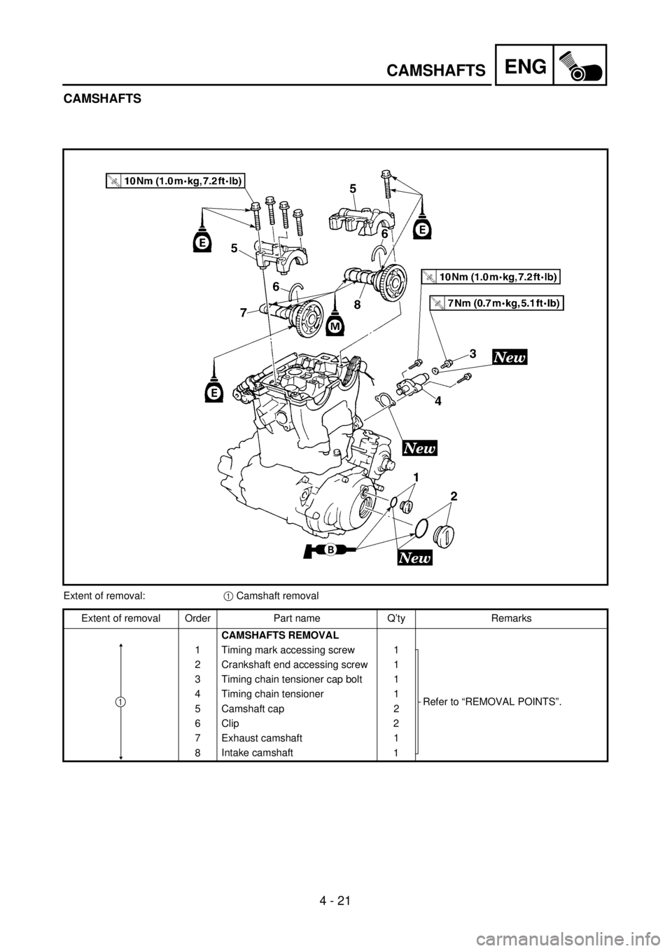
Extent of removal:1 Camshaft removal
Extent of removal Order Part name Q’ty Remarks
CAMSHAFTS REMOVAL
1 Timing mark accessing screw 1
Refer to “REMOVAL POINTS”. 2 Crankshaft end accessing screw 1
3 Timing chain tensioner cap bolt 1
4 Timing chain tensioner 1
5 Camshaft cap 2
6 Clip 2
7 Exhaust camshaft 1
8Intake camshaft
1
1
Page 309 of 686
4 - 21
ENG
ARBRES A CAMES
NOCKENWELLE
ALBERI A CAMME
NOCKENWELLE
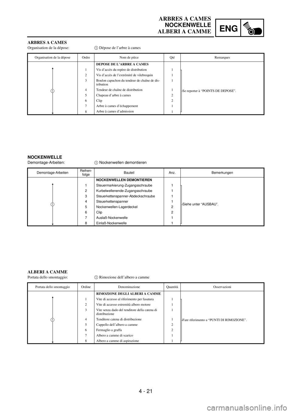
Demontage-Arbeiten:1 Nockenwellen demontieren
Demontage-ArbeitenReihen-
folgeBauteil Anz. Bemerkungen
NOCKENWELLEN DEMONTIEREN
1 Steuermarkierung-Zugangsschraube 1
Siehe unter “AUSBAU”. 2 Kurbelwellenende-Zugangsschraube 1
3 Steuerkettenspanner-Abdeckschraube 1
4 Steuerkettenspanner 1
5 Nockenwellen-Lagerdeckel 2
6 Clip 2
7 Auslaß-Nockenwelle 1
8 Einlaß-Nockenwelle 1
1
ARBRES A CAMES
Organisation de la dépose:1 Dépose de l’arbre à cames
Organisation de la dépose Ordre Nom de pièce Qté Remarques
DEPOSE DE L’ARBRE A CAMES
1 Vis d’accès du repère de distribution 1
Se reporter à “POINTS DE DEPOSE”. 2 Vis d’accès de l’extrémité de vilebrequin 1
3 Boulon capuchon du tendeur de chaîne de dis-
tribution1
4 Tendeur de chaîne de distribution 1
5 Chapeau d’arbre à cames 2
6 Clip 2
7 Arbre à cames d’échappement 1
8Arbre à cames d’admission
1
1
ALBERI A CAMME
Portata dello smontaggio:1 Rimozione dell’albero a camme
Portata dello smontaggio Ordine Denominazione Quantità Osservazioni
RIMOZIONE DEGLI ALBERI A CAMME
1 Vite di accesso al riferimento per fasatura 1
Fare riferimento a “PUNTI DI RIMOZIONE”. 2 Vite di accesso estremità albero motore 1
3 Vite senza dado del tenditore della catena di
distribuzione1
4 Tenditore catena di distribuzione 1
5 Cappello dell’albero a camme 2
6 Fermaglio a graffa 2
7 Albero a camme di scarico 1
8Albero a camme di aspirazione
1
1
Page 310 of 686

4 - 22
ENGCAMSHAFTS
REMOVAL POINTS
Camshaft
1. Remove:
lTiming mark accessing screw 1
lCrankshaft end accessing screw 2
2. Align:
lT.D.C. mark
With align mark.
Checking steps:
lTurn the crankshaft counterclockwise with
a wrench.
NOTE:
Squeezing the decompression lever allows
the crankshaft to be turned easily.
lAlign the T.D.C. mark a on the rotor with
the align mark b on the crankcase cover
when piston is at T.D.C. on compression
stroke.
NOTE:
In order to be sure that the piston is at Top
Dead Center, the punch mark c on the
exhaust camshaft and the punch mark d on
the intake camshaft must align with the cyl-
inder head surface, as shown in the illustra-
tion.
3. Remove:
lTiming chain tensioner cap bolt 1
lTiming chain tensioner 2
lGasket
4. Remove:
lBolt (camshaft cap) 1
lCamshaft cap 2
lClip
NOTE:
Remove the bolts (camshaft cap) in a criss-
cross pattern, working from the outside in.
CAUTION:
The bolts (camshaft cap) must be removed
evenly to prevent damage to the cylinder
head, camshafts or camshaft caps.