YAMAHA WR 250F 2001 Notices Demploi (in French)
Manufacturer: YAMAHA, Model Year: 2001, Model line: WR 250F, Model: YAMAHA WR 250F 2001Pages: 686, PDF Size: 62.6 MB
Page 631 of 686
–+ELEC
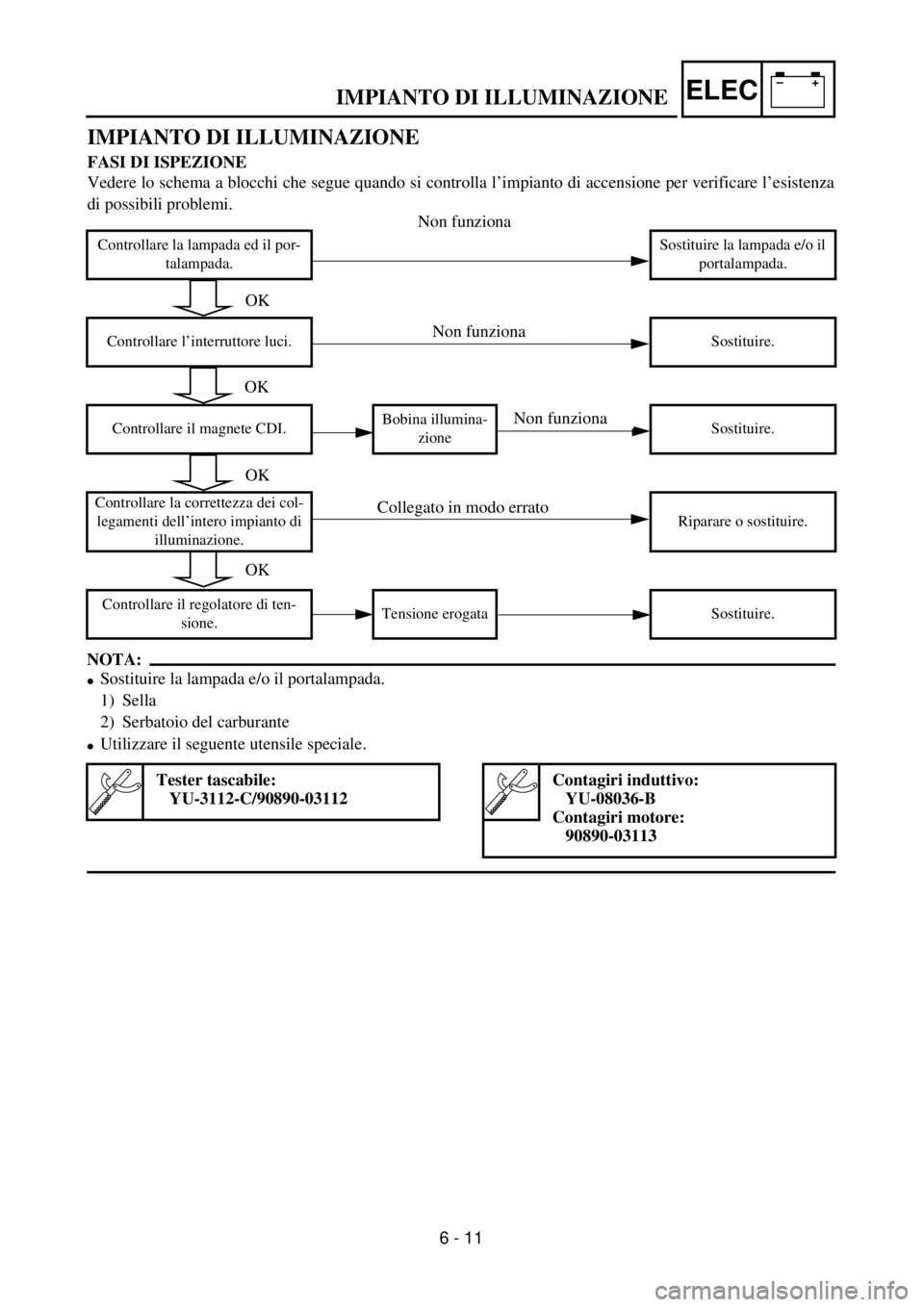
IMPIANTO DI ILLUMINAZIONE
FASI DI ISPEZIONE
Vedere lo schema a blocchi che segue quando si controlla l’impianto di accensione per verificare l’esistenza
di possibili problemi.
NOTA:
lSostituire la lampada e/o il portalampada.
1) Sella
2) Serbatoio del carburante
lUtilizzare il seguente utensile speciale.
Controllare la lampada ed il por-
talampada.Sostituire la lampada e/o il
portalampada.
Controllare l’interruttore luci. Sostituire.
Controllare il magnete CDI.Bobina illumina-
zioneSostituire.
Controllare la correttezza dei col-
legamenti dell’intero impianto di
illuminazione.Riparare o sostituire.
Controllare il regolatore di ten-
sione.Tensione erogata Sostituire.
Tester tascabile:
YU-3112-C/90890-03112Contagiri induttivo:
YU-08036-B
Contagiri motore:
90890-03113
6 - 11
IMPIANTO DI ILLUMINAZIONE
OK
OK
OK
OK
Non funziona
Collegato in modo errato
Non funziona
Non funziona
Page 632 of 686
6 - 12
–+ELECLIGHTING SYSTEM
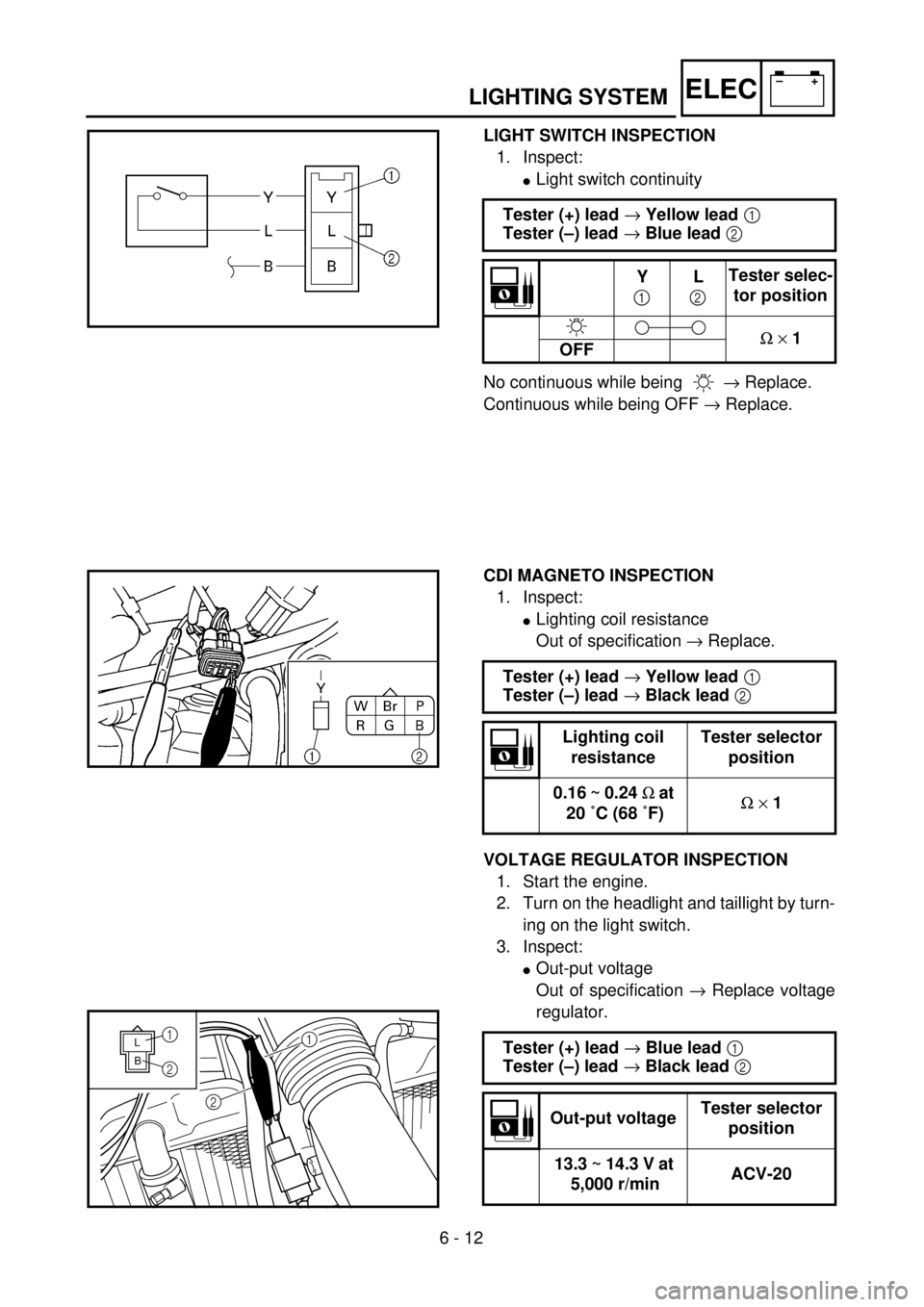
LIGHT SWITCH INSPECTION
1. Inspect:
lLight switch continuity
No continuous while being ® Replace.
Continuous while being OFF ® Replace. Tester (+) lead ® Yellow lead 1
Tester (–) lead ® Blue lead 2
Y
1L
2Tester selec-
tor position
W ´ 1
OFF
CDI MAGNETO INSPECTION
1. Inspect:
lLighting coil resistance
Out of specification ® Replace.
VOLTAGE REGULATOR INSPECTION
1. Start the engine.
2. Turn on the headlight and taillight by turn-
ing on the light switch.
3. Inspect:
lOut-put voltage
Out of specification ® Replace voltage
regulator. Tester (+) lead ® Yellow lead 1
Tester (–) lead ® Black lead 2
Lighting coil
resistanceTester selector
position
0.16 ~ 0.24 W at
20 ˚C (68 ˚F)W ´ 1
Tester (+) lead ® Blue lead 1
Tester (–) lead ® Black lead 2
Out-put voltageTester selector
position
13.3 ~ 14.3 V at
5,000 r/minACV-20
BL
1
2
1
2
Page 633 of 686
–+ELEC
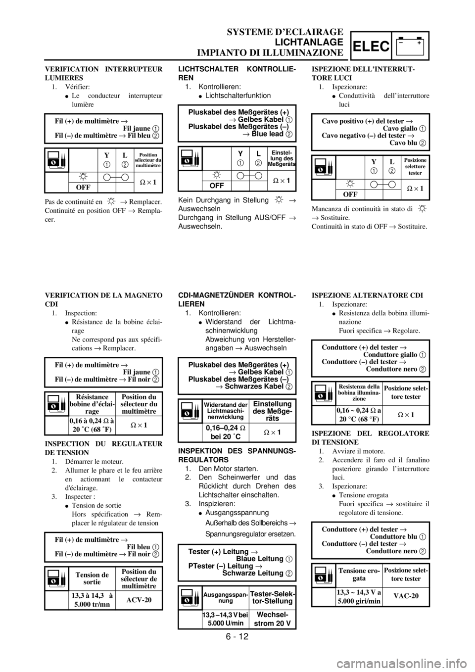
LICHTSCHALTER KONTROLLIE-
REN
1. Kontrollieren:
lLichtschalterfunktion
Kein Durchgang in Stellung
®
Auswechseln
Durchgang in Stellung AUS/OFF ®
Auswechseln.Pluskabel des Meßgerätes (+)
® Gelbes Kabel 1
Pluskabel des Meßgerätes (–)
® Blue lead 2
Y
1L
2Einstel-
lung des
Meßgeräts
W ´ 1
OFF
CDI-MAGNETZÜNDER KONTROL-
LIEREN
1. Kontrollieren:
lWiderstand der Lichtma-
schinenwicklung
Abweichung von Hersteller-
angaben ® Auswechseln
INSPEKTION DES SPANNUNGS-
REGULATORS
1. Den Motor starten.
2. Den Scheinwerfer und das
Rücklicht durch Drehen des
Lichtschalter einschalten.
3. Inspizieren:
lAusgangsspannung
Außerhalb des Sollbereichs ®
Spannungsregulator ersetzen. Pluskabel des Meßgerätes (+)
® Gelbes Kabel 1
Pluskabel des Meßgerätes (–)
® Schwarzes Kabel 2
Widerstand der
Lichtmaschi-
nenwicklungEinstellung
des Meßge-
räts
0,16–0,24 W
bei 20 ˚CW ´ 1
Tester (+) Leitung ®
Blaue Leitung 1
PTester (–) Leitung ®
Schwarze Leitung 2
Ausgangsspan-
nungTester-Selek-
tor-Stellung
13,3 –14,3 V bei
5.000 U/minWechsel-
strom 20 V
VERIFICATION INTERRUPTEUR
LUMIERES
1. Vérifier:
lLe conducteur interrupteur
lumière
Pas de continuité en ® Remplacer.
Continuité en position OFF ® Rempla-
cer.Fil (+) de multimètre ®
Fil jaune 1
Fil (–) de multimètre ® Fil bleu 2
Y
1L
2Position
sélecteur du
multimètre
W ´ 1
OFF
VERIFICATION DE LA MAGNETO
CDI
1. Inspection:
lRésistance de la bobine éclai-
rage
Ne correspond pas aux spécifi-
cations ® Remplacer.
INSPECTION DU REGULATEUR
DE TENSION
1. Démarrer le moteur.
2. Allumer le phare et le feu arrière
en actionnant le contacteur
d'éclairage.
3. Inspecter :
lTension de sortie
Hors spécification ® Rem-
placer le régulateur de tension Fil (+) de multimètre ®
Fil jaune 1
Fil (–) de multimètre ® Fil noir 2
Résistance
bobine d’éclai-
ragePosition du
sélecteur du
multimètre
0,16 à 0,24 W à
20 ˚C (68 ˚F)W ´ 1
Fil (+) de multimètre ®
Fil bleu 1
Fil (–) de multimètre ® Fil noir 2
Tension de
sortiePosition du
sélecteur de
multimètre
13,3 à 14,3 à
5.000 tr/mnACV-20
ISPEZIONE DELL’INTERRUT-
TORE LUCI
1. Ispezionare:
lConduttività dell’interruttore
luci
Mancanza di continuità in stato di
® Sostituire.
Continuità in stato di OFF ® Sostituire. Cavo positivo (+) del tester ®
Cavo giallo 1
Cavo negativo (–) del tester ®
Cavo blu 2
Y
1L
2Posizione
selettore
tester
W ´ 1
OFF
ISPEZIONE ALTERNATORE CDI
1. Ispezionare:
lResistenza della bobina illumi-
nazione
Fuori specifica ® Regolare.
ISPEZIONE DEL REGOLATORE
DI TENSIONE
1. Avviare il motore.
2. Accendere il faro ed il fanalino
posteriore girando l’interruttore
luci.
3. Ispezionare:
lTensione erogata
Fuori specifica ® sostituire il
regolatore di tensione. Conduttore (+) del tester ®
Conduttore giallo 1
Conduttore (–) del tester ®
Conduttore nero 2
Resistenza della
bobina illumina-
zionePosizione selet-
tore tester
0,16 ~ 0,24 W a
20 °C (68 °F)W ´ 1
Conduttore (+) del tester ®
Conduttore blu 1
Conduttore (–) del tester ®
Conduttore nero 2
Tensione ero-
gataPosizione selet-
tore tester
13,3 ~ 14,3 V a
5.000 giri/minVAC-20
SYSTEME D’ECLAIRAGE
LICHTANLAGE
IMPIANTO DI ILLUMINAZIONE
6 - 12
Page 634 of 686
7 - 1
TUN
EC700000
TUNING
EC710000
ENGINE
Carburetor setting
l
The air/fuel mixture will vary depending on
atmospheric conditions. Therefore, it is nec-
essary to take into consideration the air pres-
sure, ambient temperature, humidity, etc.,
when adjusting the carburetor.
l
Perform a test run to check for proper engine
performance (e.g., throttle response) and
spark plug(-s) discoloration or fouling. Use
these readings to determine the best possi-
ble carburetor setting.
NOTE:
It is recommended to keep a record of all car-
buretor settings and external conditions (e.g.,
atmospheric conditions, track/surface condi-
tions, lap times) to make future carburetor set-
ting easier.
WARNING
l
The carburetor is a part of the fuel line.
Therefore, be sure to install it in a well-
ventilated area, away from flammable
objects and any sources of fire.
l
Never look into the carburetor intake.
Flames may shoot out from the pipe if the
engine backfires while it is being started.
Gasoline may be discharged from the
accelerator pump nozzle when the carbu-
retor has been removed.
SETTING
7
Page 635 of 686
TUN
ABSTIMMUNG
MOTOR
Vergaser einstellen
l
Das Luft/Kraftstoffgemisch variiert
mit den atmosphärischen Bedin-
gungen. Daher muß die Einstel-
lung des Vergasers in Abhängig-
keit von Luftdruck, Feuchtigkeit
und Temperatur vorgenommen
werden.
l
Führen Sie eine Probefahrt durch,
um die ordnungsgemäße Motorlei-
stung (Ansprechverhalten des Mo-
tors) zu überprüfen sowie die Ver-
färbung der Zündkerze bzw. die
Ablagerungen darauf zu kontrollie-
ren. Wählen Sie unter Beachtung
dieser Punkte die bestmöglichen
Vergasereinstellungen aus.
HINWEIS:
Es wird empfohlen, die Vergaserein-
stellungen und Werte wie atmosphä-
rische Bedingungen, Zustand der
Strecke, Rundenzeiten usw. schrift-
lich festzuhalten, um zukünftige Ver-
gasereinstellungen zu erleichtern.
WARNUNG
l
Der Vergaser ist Bestandteil der
Kraftstoffanlage. Er muß daher
in einer gut belüfteten Umge-
bung montiert werden, in siche-
rer Entfernung von brennbaren
Stoffen und jeglichen Feuer-
quellen.
l
Schauen Sie niemals in den Ver-
gasereinlaß. Es können Flam-
men herausschießen, falls der
Motor beim Anlassen zurück-
schlägt. Kraftstoff kann aus der
Beschleunigungspumpe entwei-
chen, wenn der Vergaser
demontiert wurde.
REGLAGE
EINSTELLUNG
REGISTRAZIONE
MISES AU POINT
MOTEUR
Réglage de carburateur
l
La qualité de l’émulsion air/essence
dépend des conditions atmosphéri-
ques. C’est pourquoi il est nécessaire
de régler le carburateur en fonction de
la pression atmosphérique, de la tem-
pérature, de l’humidité, etc.
l
Effectuer un test de conduite afin de
contrôler les performances du moteur
(p. ex. la réponse à l’accélération) et
l’état de la bougie (décoloration ou
encrassement). Régler ensuite le car-
burateur au vu des résultats obtenus.
N.B.:
Afin de faciliter les réglages de carbura-
teur ultérieurs, il est utile de conserver
toutes les données, c.-à.-d. les réglages
correspondant aux diverses conditions
atmosphériques, conditions du terrain,
les temps, etc.
AVERTISSEMENT
l
Le carburateur fait partie du circuit
de carburant. Il est donc important
d’effectuer tout travail sur le carbu-
rateur dans un endroit bien aéré et
à une distance sûre d’objets inflam-
mables ou d’une source de flammes.
l
Ne jamais regarder à l’intérieur de
l’admission d’un carburateur. Des
flammes risquent de s’échapper du
tuyau en cas de ratés lors de la mise
en marche du moteur. De l’essence
pourrait s’écouler du gicleur de la
pompe d’accélération lorsque le
carburateur est déposé.
7 - 1
MESSA A PUNTO
MOTORE
Registrazione del carburatore
l
La miscela aria/carburante varia a
seconda delle condizioni atmosferi-
che. Pertanto, è necessario prendere in
considerazione la pressione dell’aria,
la temperatura ambiente, l’umidità,
ecc., quando si registra il carburatore.
l
Effettuare un giro di prova per con-
trollare le prestazioni corrette del
motore (ad esempio risposta della val-
vola a farfalla) e lo scolorimento o il
grado di sporco della candela. Utiliz-
zare questi valori per determinare le
migliori registrazioni possibili per il
carburatore.
NOTA:
Si consiglia di prendere nota di tutte le
registrazioni del carburatore e delle con-
dizioni esterne (ad es., condizioni atmo-
sferiche, del manto stradale, del tempo
sul giro) per agevolare la successiva
registrazione del carburatore.
AVVERTENZA
l
Il carburatore è parte della linea
carburante. Pertanto, accertarsi di
installarlo in una zona ben aerata
lontano da oggetti infiammabili e da
fonti di calore.
l
Non guardare mai nell’ammissione
del carburatore. La tubazione
potrebbe emettere fiamme se il
motore ha un ritorno di fiamma
all’avviamento. Non scaricare ben-
zina dall’ugello della pompa di cir-
colazione quando si rimuove il
carburatore.
7
Page 636 of 686

7 - 2
TUN
CAUTION:
l
The carburetor is extremely sensitive to
foreign matter (dirt, sand, water, etc.).
During installation, do not allow foreign
matter to get into the carburetor.
l
Always handle the carburetor and its
components carefully. Even slight
scratches, bends or damage to carbure-
tor parts may prevent the carburetor from
functioning correctly. Carefully perform
all servicing with the appropriate tools
and without applying excessive force.
l
When the engine is stopped or when
riding at no load, do not open and close
the throttle unnecessarily. Otherwise, too
much fuel may be discharged, starting
may become difficult or the engine may
not run well.
l
After installing the carburetor, check that
the throttle operates correctly and opens
and closes smoothly.
Atmospheric conditions and carburetor
settings
The air density (i.e., concentration of oxygen
in the air) determines the richness or lean-
ness of the air/fuel mixture. Therefore, refer
to the above table for mixture settings.
That is:
l
Higher temperature expands the air with its
resultant reduced density.
l
Higher humidity reduces the amount of oxy-
gen in the air by so much of the water vapor
in the same air.
l
Lower atmospheric pressure (at a high alti-
tude) reduces the density of the air.
Air temp. HumidityAir
pressure
(altitude)Mixture Setting
High High Low (high) Richer Leaner
Low Low High (low) Leaner Richer
SETTING
Page 637 of 686

TUN
ACHTUNG:
l
Der Vergaser ist extrem emp-
findlich gegen Fremdkörper
(Schmutz, Sand, Wasser usw.).
Darauf achten, daß bei der Mon-
tage keine Fremdkörper in den
Vergaser gelangen.
l
Mit dem Vergaser und seinen
Bauteilen immer vorsichtig
umgehen. Selbst leichte Kratzer,
Krümmungen oder Beschädi-
gungen an Vergaserteilen kön-
nen zu Fehlfunktion des
Vergasers führen. Alle War-
tungsarbeiten mit geeignetem
Werkzeug und ohne übermäßi-
gen Krafteinsatz durchführen.
l
Wenn der Motor steht oder ohne
Last dreht, den Gasdrehgriff
nicht unnötig öffnen und schlie-
ßen. Andernfalls wird zuviel
Kraftstoff geliefert, was das
Anlassen erschwert oder den
Motorlauf beeinträchtigt.
l
Nach der Montage des Verga-
sers prüfen, ob die Drossel-
klappe korrekt arbeitet und
leichtgängig öffnet und schließt.
Atmosphärische Bedingungen
und Einstellungen
Von der Luftdichte (die Sauerstoff-
konzentration in der Luft) hängt ab,
ob das Luft-Kraftstoff-Gemisch fett
oder mager ist. Beachten Sie
daher die obenstehende Tabelle
mit den Gemischeinstellungen.
Das heißt:
l
Eine höhere Temperatur führt zu
einer Ausdehnung der Luft und da-
mit zu einer geringeren Dichte.
l
Eine höhere Luftfeuchtigkeit redu-
ziert den Sauerstoffgehalt der Luft,
je mehr Wasserdampf die Luft ent-
hält.
l
Ein niedrigerer atmosphärischer
Druck (in großer Höhe) reduziert
die Dichte der Luft.
Luft-
temp.Feuch-
tig-
keitLuft-
druck
(Höhe)Gemisc
hEinstel-
lung
Hoch HochNiedrig
(hoch)FetterMage-
rer
Niedrig NiedrigHoch
(nied-
rig)Mage-
rerFetter
REGLAGE
EINSTELLUNG
REGISTRAZIONE
ATTENTION:
l
Le carburateur est extrêmement
sensible à toute pénétration de cras-
ses, sable, eau, etc. Bien veiller, lors
de tout travail sur le carburateur,
d’empêcher toute pénétration
d’objets quelconques.
l
Toujours manipuler le carburateur
et ses organes avec le plus grand
soin. Même de légères griffes, défor-
mations ou petits endommagements
peuvent empêcher son bon fonction-
nement. Effectuer soigneusement
tous les entretiens avec les outils
appropriés et sans recourir à une
force excessive.
l
Ne pas actionner sans raison la poi-
gnée des gaz lorsque le moteur est
coupé ou lorsqu’il tourne à vide. En
effet, cela provoquerait un apport
excédentaire en essence, rendant
difficile la mise en marche du
moteur ou entraînant son mauvais
fonctionnement.
l
Après la remise en place du carbu-
rateur, s’assurer que la poignée des
gaz fonctionne correctement.
Conditions atmosphériques et régla-
ges de carburateur
La densité de l’air, c.-à-d. la concen-
tration d’oxygène dans l’air, déter-
mine la richesse ou la pauvreté de
l’émulsion air/essence. Il convient dès
lors de se conformer au tableau ci-des-
sus.
La densité de l’air varie en fonction des
trois facteurs suivants:
l
La température de l’air: la densité de
l’air diminue au fur et à mesure que
l’air se dilate sous les températures
élevées.
l
Le taux d’humidité de l’air: le taux
d’oxygène diminue au fur et à mesure
que le taux d’humidité augmente.
l
Pression atmosphérique (altitude): la
densité diminue au fur et à mesure que
la pression atmosphérique descend
(altitude élevée).
Tempéra-
tureHumiditéPression
atmosphéri-
que
(altitude)Emulsion Réglage
Haute HauteBasse
(haute)Plus richePlus pau-
vre
Basse BasseHaute
(basse)Plus pau-
vrePlus riche
7 - 2
ATTENZIONE:
l
Il carburatore è estremamente sen-
sibile a materiale estraneo (sporco,
sabbia, acqua, ecc.). Durante
l’installazione, non fare penetrare
materiale estraneo nel carburatore.
l
Maneggiare sempre con molta cau-
tela il carburatore e i suoi compo-
nenti. Anche graffi, deformazioni e
anni lievi ai pezzi del carburatore ne
possono compromettere il funziona-
mento. Effettuare sempre con cau-
tela tutti gli interventi di
manutenzione utilizzando gli uten-
sili adatti e senza esercitare forza
eccessiva.
l
Quando si arresta il motore o
quando si guida in assenza di carico,
non aprire o chiudere senza neces-
sità la valvola a farfalla. Altrimenti
potrebbe venire scaricato troppo
carburante e potrebbe essere diffi-
cile avviare il motore oppure questo
potrebbe non funzionare corretta-
mente.
l
Dopo aver installato il carburatore,
controllare che la valvola a farfalla
venga azionata correttamente e si
apra e si chiuda agevolmente.
Condizioni atmosferiche e registra-
zione del carburatore
La densità dell’aria (cioè la concentra-
zione di ossigeno nell’aria) determina
se la miscela debba essere più ricca o
più povera. Pertanto, fare riferimento
alla tabella di cui sopra per la registra-
zione della miscela.
Quindi:
l
La temperatura più elevata espande
l’aria con una conseguente densità
ridotta.
l
Una umidità maggiore riduce la quan-
tità di ossigeno nell’aria in misura pro-
porzionale al vapore acqueo presente.
l
Una pressione atmosferica più bassa
(ad un’altitudine elevata) riduce la
densità dell’aria.
Temp.
dell’aria Umidità Pres-
sione
atmo-
sferica
(altitu-
dine) Miscela Regi-
strazione
Alta Alta Bassa
(alta) Più
ricca Più
povera
Bassa Bassa Alta
(bassa) Più
povera Più
ricca
Page 638 of 686
7 - 3
TUN
SETTING
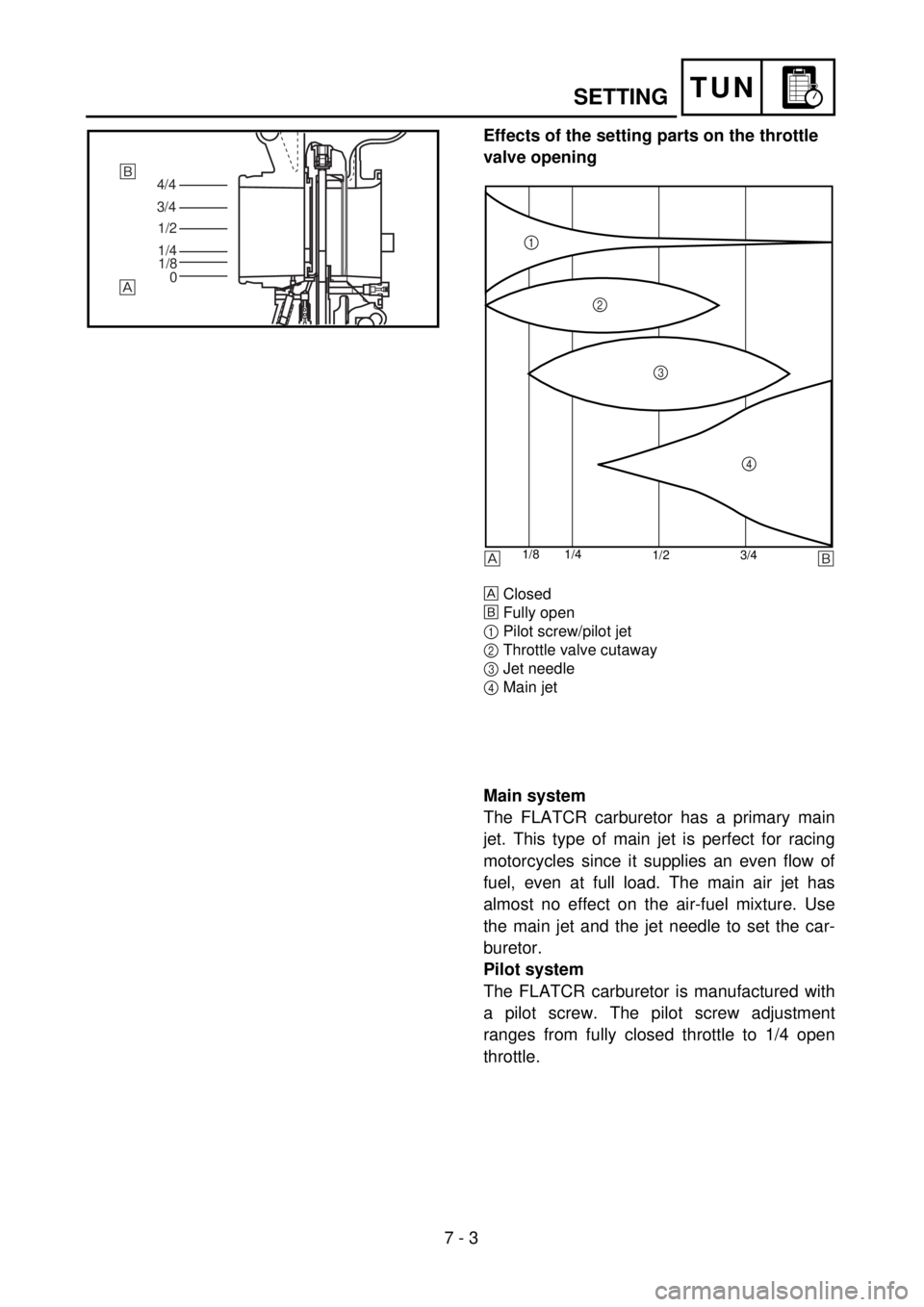
Effects of the setting parts on the throttle
valve opening
Closed
õ
Fully open
1
Pilot screw/pilot jet
2
Throttle valve cutaway
3
Jet needle
4
Main jet
4/4
3/4
1/2
1/4
1/8
0õ
1/2 3/4 1/4 1/8
1
2
3
4
õ
Main system
The FLATCR carburetor has a primary main
jet. This type of main jet is perfect for racing
motorcycles since it supplies an even flow of
fuel, even at full load. The main air jet has
almost no effect on the air-fuel mixture. Use
the main jet and the jet needle to set the car-
buretor.
Pilot system
The FLATCR carburetor is manufactured with
a pilot screw. The pilot screw adjustment
ranges from fully closed throttle to 1/4 open
throttle.
Page 639 of 686

TUN
REGLAGE
EINSTELLUNG
REGISTRAZIONE
Wirkung der Einstellteile in Bezug
auf die Öffnung der Drosselklappe
Geschlossen
õ
Vollständig geöffnet
1
Leerlauf-Regulierschraube/Leerlauf-
düse
2
Drosselklappen-Ausschnitt
3
Düsennadel
4
Hauptdüse
Hauptsystem
Der FLATCR-Vergaser verfügt über
eine Primärhauptdüse. Diese Haupt-
düsenart eignet sich ausgezeichnet
für Rennmotorräder, da sie einen
gleichmäßigen Kraftstofffluß gewähr-
leistet, selbst bei Vollast. Die Haupt-
luftdüse hat so gut wie keinen Effekt
auf das Luft-Kraftstoff-Gemisch. Der
Vergaser kann mit der Hauptdüse und
der Düsennadel eingestellt werden.
Leerlaufsystem
Der FLATCR-Vergaser verfügt über
eine Leerlauf-Regulierschraube. Die
Einstellmöglichkeit der Leerlauf-
Regulierschraube reicht von ganz
geschlossener Drosselklappe bis zu
1/4 geöffneter Drosselklappe.
Effets des réglages sur l’ouverture du
papillon des gaz
Fermé
õ
Complètement ouvert
1
Vis de ralenti/gicleur de ralenti
2
Echancrure de papillon des gaz
3
Aiguille
4
Gicleur principal
Circuit principal
Le carburateur FLATCR est équipé d’un
gicleur principal primaire. Ce type de
gicleur principal convient parfaitement
au motos de course dans la mesure où il
uniformise le débit d’essence, même à
plein rendement. Le gicleur d’air princi-
pal n’a presqu’aucun effet sur l’émulsion
air/essence. Régler le carburateur en
adaptant le gicleur principal et l’aiguille
aux conditions générales.
Circuit de ralenti
Le circuit de ralenti est équipé d’une vis
de ralenti. La plage de réglage de la vis
de ralenti varie entre la position complè-
tement fermée à ouverte d’1/4.
7 - 3
Effetti della registrazione sull’aper-
tura della valvola a farfalla
Chiusa
õ
Completamente aperta
1
Vite di registro del minimo/Getto del
minimo
2
Vista in sezione della valvola a farfalla
3
Spillo del getto
4
Getto del massimo
Sistema principale
Il carburatore FLATCR ha un getto del
massimo primario. Questo tipo di getto
del massimo è perfetto per le motoci-
clette da corsa dal momento che fornisce
un flusso di carburante omogeneo anche
a pieno carico. Il getto dell’aria del mas-
simo non ha quasi effetto sulla miscela
aria-carburante. Utilizzare il getto del
massimo e lo spillo del getto per regi-
strare il carburatore.
Sistema pilota
Il carburatore FLATCR è fabbricato con
una vite pilota. La regolazione della vita
pilota va da accelatore completamente
chiuso a 1/4 di apertura dell’accelera-
tore.
Page 640 of 686
7 - 4
TUN
SETTING
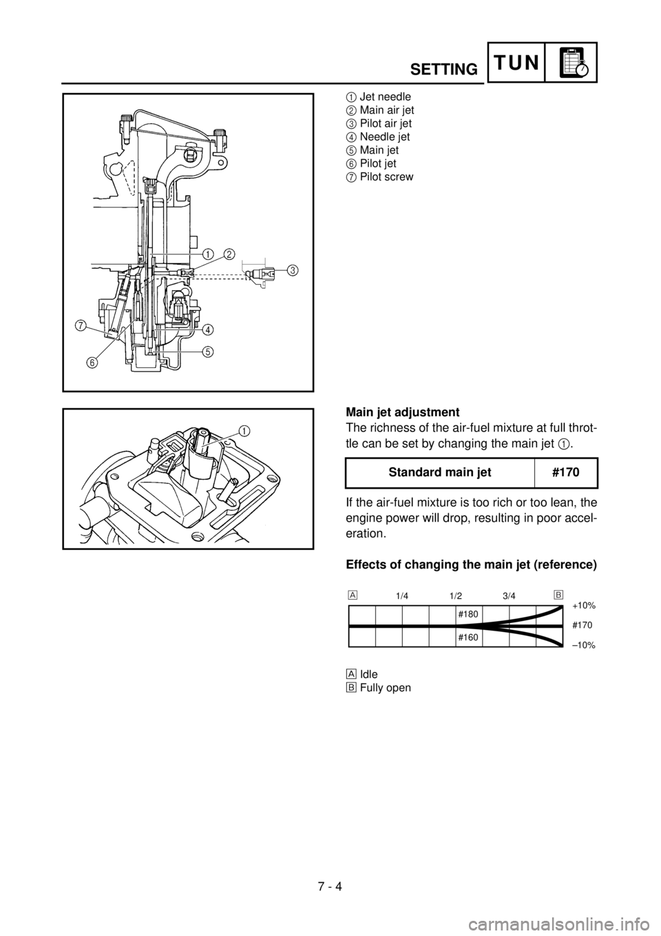
1
Jet needle
2
Main air jet
3
Pilot air jet
4
Needle jet
5
Main jet
6
Pilot jet
7
Pilot screw
Main jet adjustment
The richness of the air-fuel mixture at full throt-
tle can be set by changing the main jet
1
.
If the air-fuel mixture is too rich or too lean, the
engine power will drop, resulting in poor accel-
eration.
Effects of changing the main jet (reference)
Idle
õ
Fully open
Standard main jet #170
1/4 1/2 3/4
+10%
#170
–10%
#180
#160
õ