YAMAHA WR 250F 2003 User Guide
Manufacturer: YAMAHA, Model Year: 2003, Model line: WR 250F, Model: YAMAHA WR 250F 2003Pages: 860, PDF Size: 35.16 MB
Page 11 of 860

WICHTIGER HINWEIS
AN DEN
EIGENTÜMER
Damit Sie alle Vorzüge dieses Motor-
rades nutzen können, lesen Sie bitte
diese Anleitung sorgfältig durch,
auch wenn dies Ihre wertvolle Zeit in
Anspruch nimmt. Denn Sie erfahren
nicht nur, wie Sie Ihre Maschine am
besten bedienen, inspizieren und
warten, sondern auch wie Sie sich
vor Unfällen schützen.
Wenn Sie die vielen Tips der Bedie-
nungsanleitung nutzen, garantieren
wir den bestmöglichen Werterhalt
dieses Motorrades. Sollten Sie dar-
über hinaus noch weitere Fragen
haben, wenden Sie sich an den
nächsten Yamaha-Händler Ihres
Vertrauens.
HINWEIS:
Die Anleitung ist ein wichtiger
Bestandteil des Fahrzeugs und sollte
daher beim eventuellen Weiterver-
kauf an den neuen Eigentümer über-
geben werden.
ANMERKUNG
Die Angaben dieser Anleitung
befinden sich zum Zeitpunkt der
Drucklegung auf dem neuesten
Stand. Aufgrund der kontinuierli-
chen Bemühungen von Yamaha
um technischen Fortschritt und
Qualitätssteigerung können einige
Angaben jedoch für Ihr Modell
nicht mehr zutreffen. Richten Sie
Fragen zu dieser Anleitung bitte
an Ihren Yamaha-Händler.
GEWICHT DER
F.I.M.-MASCHINE:
Gewicht der Maschine ohne
Kraftstoff
Das Mindestgewicht für eine
Motocross- Maschine ist:
für 125 cc Klasse ........... Mindest
88 kg (194 lb)
für 250 cc Klasse ........... Mindest
98 kg (216 lb)
für 500 cc Klasse ........... Mindest
102 kg (225 lb)
Falls Sie Modifikationen an lhrer
Maschine vornehmen (z.B. zur
Gewichtsverringerung), unbe-
dingt das oben angeführte Min-
destgewicht lhre Klasse einhalten.
PER IL NUOVO
PROPRIETARIO
Questo manuale consente di acquisire
una buona conoscenza delle caratteristi-
che, del funzionamento e degli interventi
di manutenzione ed ispezione fondamen-
tali di questo veicolo. Leggere attenta-
mente e completamente questo manuale
prima di mettere in funzione il nuovo
veicolo. In caso di domande in relazione
al funzionamento o alla manutenzione
del veicolo, consultare il proprio rivendi-
tore Yamaha.
NOTA:
Questo manuale va considerato parte
integrante del veicolo e deve accompa-
gnare il veicolo anche se in seguito que-
sta venisse rivenduta.
AVVERTENZA
Alcuni dati di questo manuale potreb-
bero risultare obsoleti a causa di
aggiornamenti apportati a questo
modello in futuro. In caso di domande
in relazione a questo manuale o al vei-
colo, rivolgersi al proprio rivenditore
Yamaha.
PESO MOTOCICLETTA:
Peso del veicolo senza carburante
I pesi minimi per le motociclette da
motocross sono:
per la classe 125 cc ............. minimo
88 kg (194 lb)
per la classe 250 cc ............. minimo
98 kg (216 lb)
per la classe 500 cc ............. minimo
102 kg (225 lb)
Se si apportano modifiche al veicolo,
(ad es.: per ridurne il peso), tenere
presenti i limiti di peso di cui sopra.
NUEVO
PROPIETARIO
Este manual le proporcionará una
comprensión elemental óptima sobre
las funciones, funcionamiento, man-
tenimiento e inspecciones básicas
de los ítems de este vehículo. Lea
detenidamente este manual antes de
manejar su nuevo vehículo. Para
cualquier aclaración referente al fun-
cionamiento o mantenimiento del
vehículo, consulte con su concesio-
nario Yamaha.
Este manual debe considerarse
como una pieza permanente del
vehículo y debe permanecer en el
mismo incluso en el caso de que el
vehículo sea vendido posterior-
mente.
NOTA:
Este manual debe ser considerado
como un elemento importante de
este vehículo y permanecer en el
mismo aún en caso de ser vendido
posteriormente.
AVISO
Algunos datos de este manual
pueden quedar obsoletos debido
a las mejoras realizadas a este
modelo en el futuro. Si tiene cual-
quier duda con relación a este
manual o a su vehículo, consulte
con su concesionario Yamaha.
PESOS DEL VEHÍCULO
F.I.M.:
Pesos del vehículo sin combus-
tible
Los pesos mínimos de los vehícu-
los de motocross son:
para 125 cc ..................... mínimo
88 kg (194 lb)
para 250 cc ..................... mínimo
98 kg (216 lb)
para 500 cc ..................... mínimo
102 kg (225 lb)
Si va a modificar su vehículo (por
ejemplo, reducir el peso), tenga
en cuenta los límites de peso des-
critos anteriormente.
Page 12 of 860
EC080000
HOW TO USE THIS
MANUAL
EC081000
PARTICULARLY
IMPORTANT
INFORMATION
The Safety Alert Symbol means
ATTENTION! BECOME ALERT!
YOUR SAFETY IS INVOLVED!
Failure to follow WARNING instruc-
tions could result in severe injury or
death to the machine operator, a
bystander, or a person inspecting or
repairing the machine.
A CAUTION indicates special pre-
cautions that must be taken to avoid
damage to the machine.
NOTE:
A NOTE provides key information to
make procedures easier or clearer.
WARNING
CAUTION:
EC082000FINDING THE REQUIRED
PAGE
1. This manual consists of seven
chapters; “General information”,
“Specifications”, “Regular
inspection and adjustments”,
“Engine”, “Chassis”, “Electrical”
and “Tuning”.
2. The table of contents is at the
beginning of the manual. Look
over the general layout of the
book before finding then
required chapter and item.
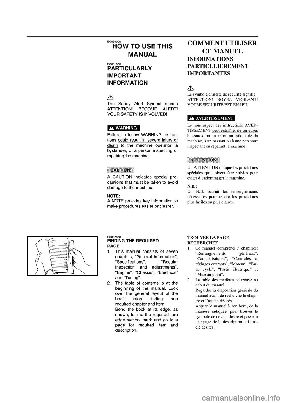
Bend the book at its edge, as
shown, to find the required fore
edge symbol mark and go to a
page for required item and
description.
COMMENT UTILISER
CE MANUEL
INFORMATIONS
PARTICULIEREMENT
IMPORTANTES
Le symbole d’alerte de sécurité signifie
ATTENTION! SOYEZ VIGILANT!
VOTRE SECURITE EST EN JEU!
Le non-respect des instructions AVER-
TISSEMENT peut entraîner de sérieuses
blessures ou la mort au pilote de la
machine, à un passant ou à une personne
inspectant ou réparant la machine.
Un ATTENTION indique les procédures
spéciales qui doivent être suivies pour
éviter d’endommager la machine.
N.B.:
Un N.B. fournit les renseignements
nécessaires pour rendre les procédures
plus faciles ou plus claires.
AVERTISSEMENT
ATTENTION:
TROUVER LA PAGE
RECHERCHEE
1. Ce manuel comprend 7 chapitres:
“Renseignements généraux”,
“Caractéristiques”, “Controles et
réglages courants”, “Moteur”, “Par-
tie cycle”, “Partie électrique” et
“Mise au point”.
2. La table des matières se trouve au
début du manuel.
Regarder la disposition générale du
manuel avant de recherche le chapi-
tre et l’article désirés.
Arquer le manuel à son bord, de la
manière indiquée, pour trouver le
symbole de devant désiré et passer à
une page de la description et l’arti-
cle désirés.
Page 13 of 860
BENUTZERHINWEISE
KENNZEICHNUNG
WICHTIGER HINWEISE
Das Ausrufezeichen bedeutet:
“GEFAHR! Achten Sie auf Ihre
Sicherheit!”
Ein Mißachten dieser Warnhinweise
bringt Fahrer, Mechaniker und
andere Personen in Verletzungs-
oder Lebensgefahr.
Hierunter sind Vorsichtsmaßnah-
men zum Schutz des Fahrzeugs vor
Schäden aufgeführt.
HINWEISE:
Ein HINWEIS gibt Zusatzinformatio-
nen und Tips, um bestimmte Vor-
gänge oder Arbeiten zu
vereinfachen.
WARNUNG
ACHTUNG:
INFORMATION AUFFINDEN
1. Diese Anleitung umfaßt sieben
Kapitel: 1. Allgemeine Angaben
– 2. Technische Daten – 3.
Regelmässige Inspektion und
Einstellarbeiten – 4. Motor – 5.
Fahrwerk – 6. Elektrische
Anlage – 7. Abstimmung
2. Dem ersten Kapitel geht ein
Inhaltverzeichnis voran. Machen
Sie sich mit dem Inhalt und Auf-
bau der Anleitung vertraut, bevor
Sie nach bestimmten Angaben
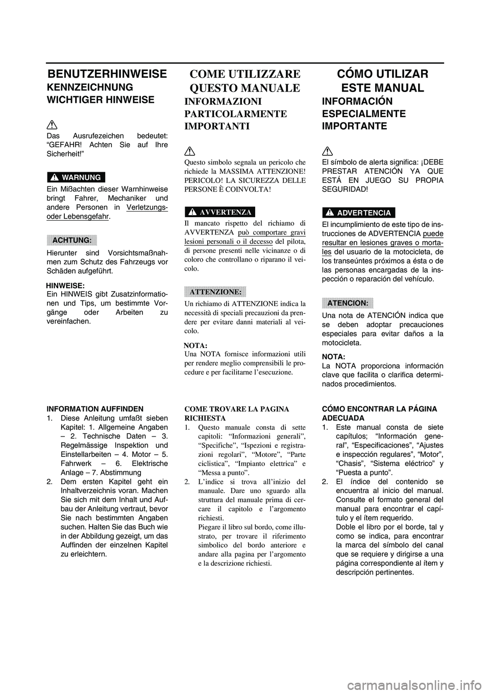
suchen. Halten Sie das Buch wie
in der Abbildung gezeigt, um das
Auffinden der einzelnen Kapitel
zu erleichtern.
COME UTILIZZARE
QUESTO MANUALE
INFORMAZIONI
PARTICOLARMENTE
IMPORTANTI
Questo simbolo segnala un pericolo che
richiede la MASSIMA ATTENZIONE!
PERICOLO! LA SICUREZZA DELLE
PERSONE È COINVOLTA!
Il mancato rispetto del richiamo di
AVVERTENZA può comportare gravi
lesioni personali o il decesso del pilota,
di persone presenti nelle vicinanze o di
coloro che controllano o riparano il vei-
colo.
Un richiamo di ATTENZIONE indica la
necessità di speciali precauzioni da pren-
dere per evitare danni materiali al vei-
colo.
NOTA:
Una NOTA fornisce informazioni utili
per rendere meglio comprensibili le pro-
cedure e per facilitarne l’esecuzione.
AVVERTENZA
ATTENZIONE:
COME TROVARE LA PAGINA
RICHIESTA
1. Questo manuale consta di sette
capitoli: “Informazioni generali”,
“Specifiche”, “Ispezioni e registra-
zioni regolari”, “Motore”, “Parte
ciclistica”, “Impianto elettrica” e
“Messa a punto”.
2. L’indice si trova all’inizio del
manuale. Dare uno sguardo alla
struttura del manuale prima di cer-
care il capitolo e l’argomento
richiesti.
Piegare il libro sul bordo, come illu-
strato, per trovare il riferimento
simbolico del bordo anteriore e
andare alla pagina per l’argomento
e la descrizione richiesti.
CÓMO UTILIZAR
ESTE MANUAL
INFORMACIÓN
ESPECIALMENTE
IMPORTANTE
El símbolo de alerta significa: ¡DEBE
PRESTAR ATENCIÓN YA QUE
ESTÁ EN JUEGO SU PROPIA
SEGURIDAD!
El incumplimiento de este tipo de ins-
trucciones de ADVERTENCIA puede
resultar en lesiones graves o morta-
les del usuario de la motocicleta, de
los transeúntes próximos a ésta o de
las personas encargadas de la ins-
pección o reparación del vehículo.
Una nota de ATENCIÓN indica que
se deben adoptar precauciones
especiales para evitar daños a la
motocicleta.
NOTA:
La NOTA proporciona información
clave que facilita o clarifica determi-
nados procedimientos.
ADVER TENCIA
ATENCION:
CÓMO ENCONTRAR LA PÁGINA
ADECUADA
1. Este manual consta de siete
capítulos; “Información gene-
ral”, “Especificaciones”, “Ajustes
e inspección regulares”, “Motor”,
“Chasis”, “Sistema eléctrico” y
“Puesta a punto”.
2. El índice del contenido se
encuentra al inicio del manual.
Consulte el formato general del
manual para encontrar el capí-
tulo y el ítem requerido.
Doble el libro por el borde, tal y
como se indica, para encontrar
la marca del símbolo del canal
que se requiere y dirigirse a una
página correspondiente al ítem y
descripción pertinentes.
Page 14 of 860
EC083000
MANUAL FORMAT
All of the procedures in this manual are organized in a
sequential, step-by-step format. The information has
been complied to provide the mechanic with an easy to
read, handy reference that contains comprehensive
explanations of all disassembly, repair, assembly, and
inspection operations.
In this revised format, the condition of a faulty component
will precede an arrow symbol and the course of action
required will follow the symbol, e.g.,
Bearings
Pitting/damage
→ Replace.
EC084002
HOW TO READ DESCRIPTIONS
To help identify parts and clarify procedure steps, there
are exploded diagrams at the start of each removal and
disassembly section.
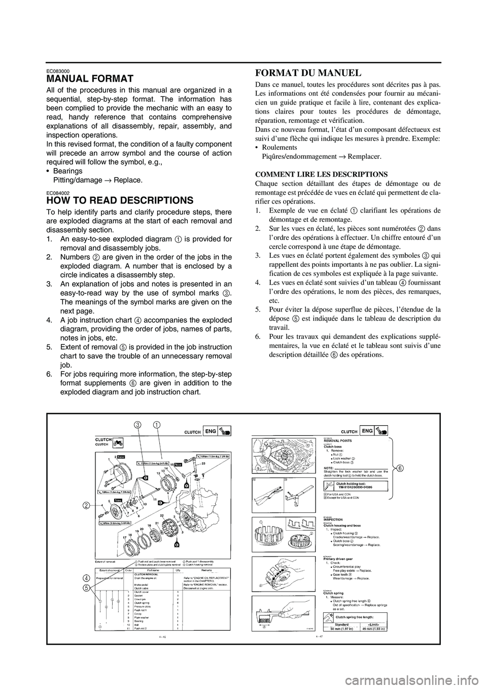
1. An easy-to-see exploded diagram
1 is provided for
removal and disassembly jobs.
2. Numbers
2 are given in the order of the jobs in the
exploded diagram. A number that is enclosed by a
circle indicates a disassembly step.
3. An explanation of jobs and notes is presented in an
easy-to-read way by the use of symbol marks
3.
The meanings of the symbol marks are given on the
next page.
4. A job instruction chart
4 accompanies the exploded
diagram, providing the order of jobs, names of parts,
notes in jobs, etc.
5. Extent of removal
5 is provided in the job instruction
chart to save the trouble of an unnecessary removal
job.
6. For jobs requiring more information, the step-by-step
format supplements
6 are given in addition to the
exploded diagram and job instruction chart.
FORMAT DU MANUEL
Dans ce manuel, toutes les procédures sont décrites pas à pas.
Les informations ont été condensées pour fournir au mécani-
cien un guide pratique et facile à lire, contenant des explica-
tions claires pour toutes les procédures de démontage,
réparation, remontage et vérification.
Dans ce nouveau format, l’état d’un composant défectueux est
suivi d’une flèche qui indique les mesures à prendre. Exemple:
Roulements
Piqûres/endommagement → Remplacer.
COMMENT LIRE LES DESCRIPTIONS
Chaque section détaillant des étapes de démontage ou de
remontage est précédée de vues en éclaté qui permettent de cla-
rifier ces opérations.
1. Exemple de vue en éclaté 1 clarifiant les opérations de
démontage et de remontage.
2. Sur les vues en éclaté, les pièces sont numérotées 2 dans
l’ordre des opérations à effectuer. Un chiffre entouré d’un
cercle correspond à une étape de démontage.
3. Les vues en éclaté portent également des symboles 3 qui
rappellent des points importants à ne pas oublier. La signi-
fication de ces symboles est expliquée à la page suivante.
4. Les vues en éclaté sont suivies d’un tableau 4 fournissant
l’ordre des opérations, le nom des pièces, des remarques,
etc.
5. Pour éviter la dépose superflue de pièces, l’étendue de la
dépose 5 est indiquée dans le tableau de description du
travail.
6. Pour les travaux qui demandent des explications supplé-
mentaires, la vue en éclaté et le tableau sont suivis d’une
description détaillée 6 des opérations.
Page 15 of 860
AUFBAU
Diese Anleitung wurde zusammen-
gestellt, um dem Benutzer ein leicht
verständliches Nachschlagewerk in
die Hand zu geben, in dem alle dar-
gestellten Arbeitsvorgänge (Ein- und
Ausbau, Zerlegung und Zusammen-
bau, Prüfung und Reparatur) detail-
liert und in der entsprechenden
Reihenfolge beschrieben sind.
Je nach Zustand eines fehlerhaften
Bauteils weist ein Pfeilsymbol auf die
erforderliche Maßnahme hin. Bei-
spiel:
Lager
Pitting/Beschädigung → Erneuern.
LESEN DER BESCHREIBUNGEN
Um bei der Identifikation der Teile zu
helfen und die Arbeitsschritte zu ver-
deutlichen, sind Explosionsdia-
gramme am Beginn jedes Ausbau-
und Demontageabschnittes darge-
stellt.
1. Für die Ausbau- und Demonta-
gearbeiten ist meistens ein über-
sichtliches Explosionsdiagramm
1 dargestellt.
2. Die Nummern 2 in dem Explosi-
onsdiagramm sind in der Rei-
henfolge der Arbeiten
aufgeführt. Eine in einen Kreis
eingeschriebene Nummer
bezeichnet einen Demontage-
schritt.
3. Eine Erläuterung der Arbeiten
und Hinweise ist durch ablese-
freundliche Symbolmarkierun-
gen 3 gegeben. Die
Bedeutungen der Symbolmar-
kierungen sind auf der nächsten
Seite aufgeführt.
4. Eine Arbeitsanweisungstabelle
4 begleitet das Explosionsdia-
gramm und gibt die Arbeitsrei-
henfolge, Bezeichnung der
Teile, Hinweise zu den Arbeiten
usw. an.
5. Der Umfang des Ausbaus 5 ist
in der Arbeitsanweisungstabelle
aufgeführt, um nicht erforderli-
che Ausbauarbeiten zu vermei-
den.
6. Für Arbeiten, für die weitere
Informationen benötigt werden,
sind schrittweise Ergänzungen
6 zusätzlich zu dem Explosi-
onsdiagramm und der Arbeitsan-
weisungstabelle aufgeführt.
STRUTTURA DEL
MANUALE
Tutte le procedure di questo manuale
sono organizzate in sequenze passo a
passo. Le informazioni sono state redatte
in modo tale da fornire al meccanico un
riferimento comodo e di agevole lettura
che comprenda, al contempo, spiega-
zioni complete relative alle operazioni di
smontaggio, riparazione, montaggio ed
ispezione.
In questo nuovo formato, la condizione
di un componente non funzionante pre-
cede una freccia e l’azione richiesta
segue il simbolo., ad es.:
Cuscinetti
Puntinatura/danno → Sostituire.
COME LEGGERE LE
DESCRIZIONI
Allo scopo di agevolare l’identificazione
dei pezzi e di chiarire le fasi delle varie
procedure, sono state inserite rappresen-
tazioni esplose all’inizio di ciascun para-
grafo dedicato alla rimozione e allo
smontaggio.
1. Una rappresentazione esplosa di
immediata comprensione 1 viene
fornita per agevolare le operazioni
di rimozione e smontaggio.
2. I numeri 2 sono indicati nella rap-
presentazione esplosa secondo la
sequenza di lavoro. Un numero rac-
chiuso in un cerchietto indica una
fase di un’operazione di smontag-
gio.
3. Una spiegazione delle operazioni e
delle note viene illustrata in maniera
chiara dall’impiego di riferimenti
simbolici 3. Il significato dei riferi-
menti simbolici viene fornito alla
pagina seguente.
4. Uno schema di istruzioni di lavoro
4 unitamente alla rappresenta-
zione esplosa, fornisce la sequenza
dei lavori, i nomi dei pezzi, le note
relative ai lavori, ecc.
5. L’indicazione relativa alla portata
dell’intervento di rimozione 5
viene fornita nello schema di istru-
zioni per evitare operazioni di rimo-
zione non necessaire.
6. Per quegli interventi che richiedono
maggiori informazioni, vengono
forniti supplementi in formato passo
a passo 6 oltre alla rappresenta-
zione esplosa e allo schema di istru-
zioni.
FORMATO DEL MANUAL
Todos los procedimientos de este
manual están organizados secuen-
cialmente, paso por paso. La infor-
mación ha sido recopilada para
proporcionar al mecánico una lectura
fácil y material útil de referencia que
contiene amplias explicaciones de
todos los desmontajes, reparacio-
nes e inspecciones.
En este formato revisado, el estado
de un componente defectuoso estará
precedido de una flecha y, a conti-
nuación, se indica el procedimiento
necesario, por ejemplo,
Cojinetes
Picaduras/daños → Reemplazar.
CÓMO LEER LAS
DESCRIPCIONES
Para ayudar a identificar las piezas o
clarificar los pasos de los procedi-
mientos, se facilitan diagramas de
despiece al comienzo de cada apar-
tado de extracción y desmontaje.
1. El diagrama de despiece 1 per-
mite identificar fácilmente los
componentes de las tareas de
extracción y desmontaje.
2. Los números 2 indican el orden
de las tareas del diagrama de
despiece. Los números repre-
sentados dentro de un círculo
indican un paso de la tarea de
desmontaje.
3. La explicación de las tareas y
notas está representada de
forma sencilla mediante símbo-
los 3. En la siguiente página
aparece el significado de dichos
símbolos.
4. El diagrama de despiece incluye
una tabla 4 que explica los
pasos de la tarea, los nombres
de las piezas, las notas para las
tareas, etc.
5. La tabla de instrucciones incluye
una extensión de la extracción
5 para evitar que se extraigan
piezas innecesariamente.
6. Cuando los contenidos requie-
ran más información, los suple-
mentos de formato paso a paso
6 proporcionan notas informati-
vas de los diagramas de des-
piece y el contenido de la tabla
de instrucción.
Page 16 of 860

ILLUSTRATED SYMBOLS
(Refer to the illustration)
Illustrated symbols 1 to 7 are
designed as thumb tabs to indicate
the chapter’s number and content.
1General information
2Specifications
3Regular inspection and adjustments
4Engine
5Chassis
6Electrical
7Tuning
Illustrated symbols 8 to D are used
to identify the specifications appear-
ing in the text.
8With engine mounted
9Special tool
0Filling fluid
ALubricant
BTightening
CSpecified value, Service limit
DResistance (Ω
), Voltage (V), Electric
current (A)
Illustrated symbols E to H in the
exploded diagrams indicate grade of
lubricant and location of lubrication
point.
EApply engine oil
FApply molybdenum disulfide oil
GApply lightweight lithium-soap base
grease
HApply molybdenum disulfide grease
Illustrated symbols I to J in the
exploded diagrams indicate where to
apply a locking agent and where to
install new parts.
IApply locking agent (LOCTITE®)
JUse new one
SYMBOLES
GRAPHIQUES
(Voir l’illustration)
Les symboles graphiques 1 à 7 servent
à repérer les différents chapitres et à
indiquer leur contenu.
1
Renseignements généraux
2
Caractéristiques
3
Controles et réglages courants
4
Moteur
5
Partie cycle
6
Partie électrique
7
Mises au point
Les symboles graphiques 8 à D per-
mettent d’identifier les spécifications
encadrées dans le texte.
8
Avec de montage du moteur
9
Outil spécial
0
Liquide de remplissage
A
Lubrifiant
B
Serrage
C
Valeur spécifiée, limite de service
D
Résistance (Ω
), tension (V), intensité (A)
Les symboles graphiques E à H utilisés
dans les vues en éclaté indiquent les
endroit à lubrifier et le type de lubrifiant.
E
Appliquer de l’huile moteur
F
Appliquer de l’huile au bisulfure de
molybdène
G
Appliquer de la graisse fluide à base de
savon au lithium
H
Appliquer de la graisse au bisulfure de
molybdène
Les symboles graphiques I à J dans
les vues en éclaté indiquent le produit de
blocage à appliquer et les pièces qui
nécessitent un remplacement.
I
Appliquer un agent de blocage
(LOCTITE®)
J
Utiliser une pièce neuve. 12
34
56
78
90
AB
CD
EF
GH
IJ
GEN
INFOSPEC
INSP
ADJENG
CHAS–+ELEC
TUN
T R..
EM
BM
New
Page 17 of 860
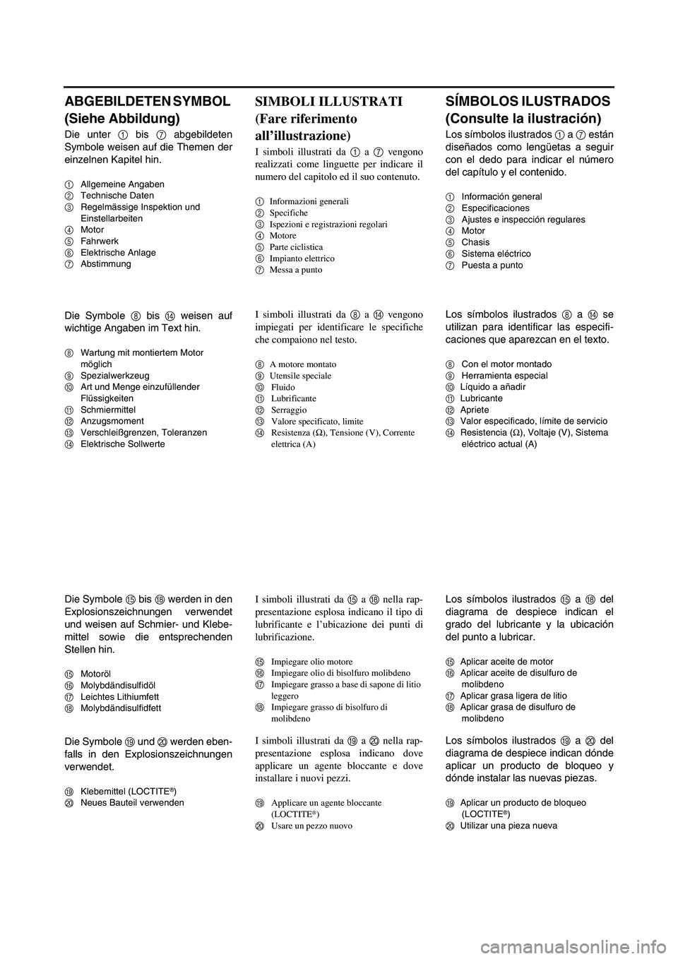
ABGEBILDETEN SYMBOL
(Siehe Abbildung)
Die unter 1 bis 7 abgebildeten
Symbole weisen auf die Themen der
einzelnen Kapitel hin.
1Allgemeine Angaben
2Technische Daten
3Regelmässige Inspektion und
Einstellarbeiten
4Motor
5Fahrwerk
6Elektrische Anlage
7Abstimmung
Die Symbole 8 bis D weisen auf
wichtige Angaben im Text hin.
8Wartung mit montiertem Motor
möglich
9Spezialwerkzeug
0Art und Menge einzufüllender
Flüssigkeiten
ASchmiermittel
BAnzugsmoment
CVerschleißgrenzen, Toleranzen
DElektrische Sollwerte
Die Symbole E bis H werden in den
Explosionszeichnungen verwendet
und weisen auf Schmier- und Klebe-
mittel sowie die entsprechenden
Stellen hin.
EMotoröl
FMolybdändisulfidöl
GLeichtes Lithiumfett
HMolybdändisulfidfett
Die Symbole I und J werden eben-
falls in den Explosionszeichnungen
verwendet.
IKlebemittel (LOCTITE®)
JNeues Bauteil verwenden
SIMBOLI ILLUSTRATI
(Fare riferimento
all’illustrazione)
I simboli illustrati da 1 a 7 vengono
realizzati come linguette per indicare il
numero del capitolo ed il suo contenuto.
1
Informazioni generali
2
Specifiche
3
Ispezioni e registrazioni regolari
4
Motore
5
Parte ciclistica
6
Impianto elettrico
7
Messa a punto
I simboli illustrati da 8 a D vengono
impiegati per identificare le specifiche
che compaiono nel testo.
8
A motore montato
9
Utensile speciale
0
Fluido
A
Lubrificante
B
Serraggio
C
Valore specificato, limite
D
Resistenza (Ω
), Tensione (V), Corrente
elettrica (A)
I simboli illustrati da E a H nella rap-
presentazione esplosa indicano il tipo di
lubrificante e l’ubicazione dei punti di
lubrificazione.
E
Impiegare olio motore
F
Impiegare olio di bisolfuro molibdeno
G
Impiegare grasso a base di sapone di litio
leggero
H
Impiegare grasso di bisolfuro di
molibdeno
I simboli illustrati da I a J nella rap-
presentazione esplosa indicano dove
applicare un agente bloccante e dove
installare i nuovi pezzi.
I
Applicare un agente bloccante
(LOCTITE®)
J
Usare un pezzo nuovo
SÍMBOLOS ILUSTRADOS
(Consulte la ilustración)
Los símbolos ilustrados 1 a 7 están
diseñados como lengüetas a seguir
con el dedo para indicar el número
del capítulo y el contenido.
1Información general
2Especificaciones
3Ajustes e inspección regulares
4Motor
5Chasis
6Sistema eléctrico
7Puesta a punto
Los símbolos ilustrados 8 a D se
utilizan para identificar las especifi-
caciones que aparezcan en el texto.
8Con el motor montado
9Herramienta especial
0Líquido a añadir
ALubricante
BApriete
CValor especificado, límite de servicio
DResistencia (Ω
), Voltaje (V), Sistema
eléctrico actual (A)
Los símbolos ilustrados E a H del
diagrama de despiece indican el
grado del lubricante y la ubicación
del punto a lubricar.
EAplicar aceite de motor
FAplicar aceite de disulfuro de
molibdeno
GAplicar grasa ligera de litio
HAplicar grasa de disulfuro de
molibdeno
Los símbolos ilustrados I a J del
diagrama de despiece indican dónde
aplicar un producto de bloqueo y
dónde instalar las nuevas piezas.
IAplicar un producto de bloqueo
(LOCTITE®)
JUtilizar una pieza nueva
Page 18 of 860

EC090010
INDEX
GENERAL
INFORMATION
SPECIFICATIONS
REGULAR
INSPECTION AND
ADJUSTMENTS
ENGINE
CHASSIS
ELECTRICAL
TUNING
INDEX
RENSEIGNEMENTS
GENERAUX
CARACTERISTI-
QUES
CONTROLES ET
REGLAGES
COURANTS
MOTEUR
PARTIE CYCLE
PARTIE
ELECTRIQUE
MISES AU POINT
Page 19 of 860
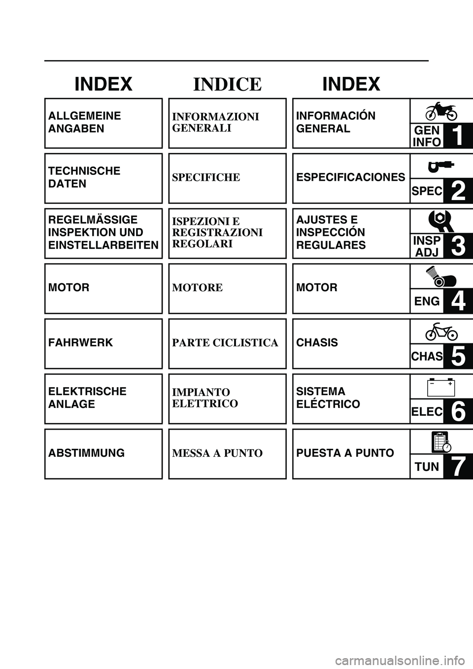
INDEX
ALLGEMEINE
ANGABEN
TECHNISCHE
DATEN
REGELMÄSSIGE
INSPEKTION UND
EINSTELLARBEITEN
MOTOR
FAHRWERK
ELEKTRISCHE
ANLAGE
ABSTIMMUNG
INDICE
INFORMAZIONI
GENERALI
SPECIFICHE
ISPEZIONI E
REGISTRAZIONI
REGOLARI
MOTORE
PARTE CICLISTICA
IMPIANTO
ELETTRICO
MESSA A PUNTO
INDEX
INFORMACIÓN
GENERAL
GEN
INFO
1
ESPECIFICACIONES
SPEC2
AJUSTES E
INSPECCIÓN
REGULARES
INSP
ADJ
3
MOTOR
ENG4
CHASIS
CHAS5
SISTEMA
ELÉCTRICO
ELEC6
PUESTA A PUNTO
TUN7
–+
Page 20 of 860
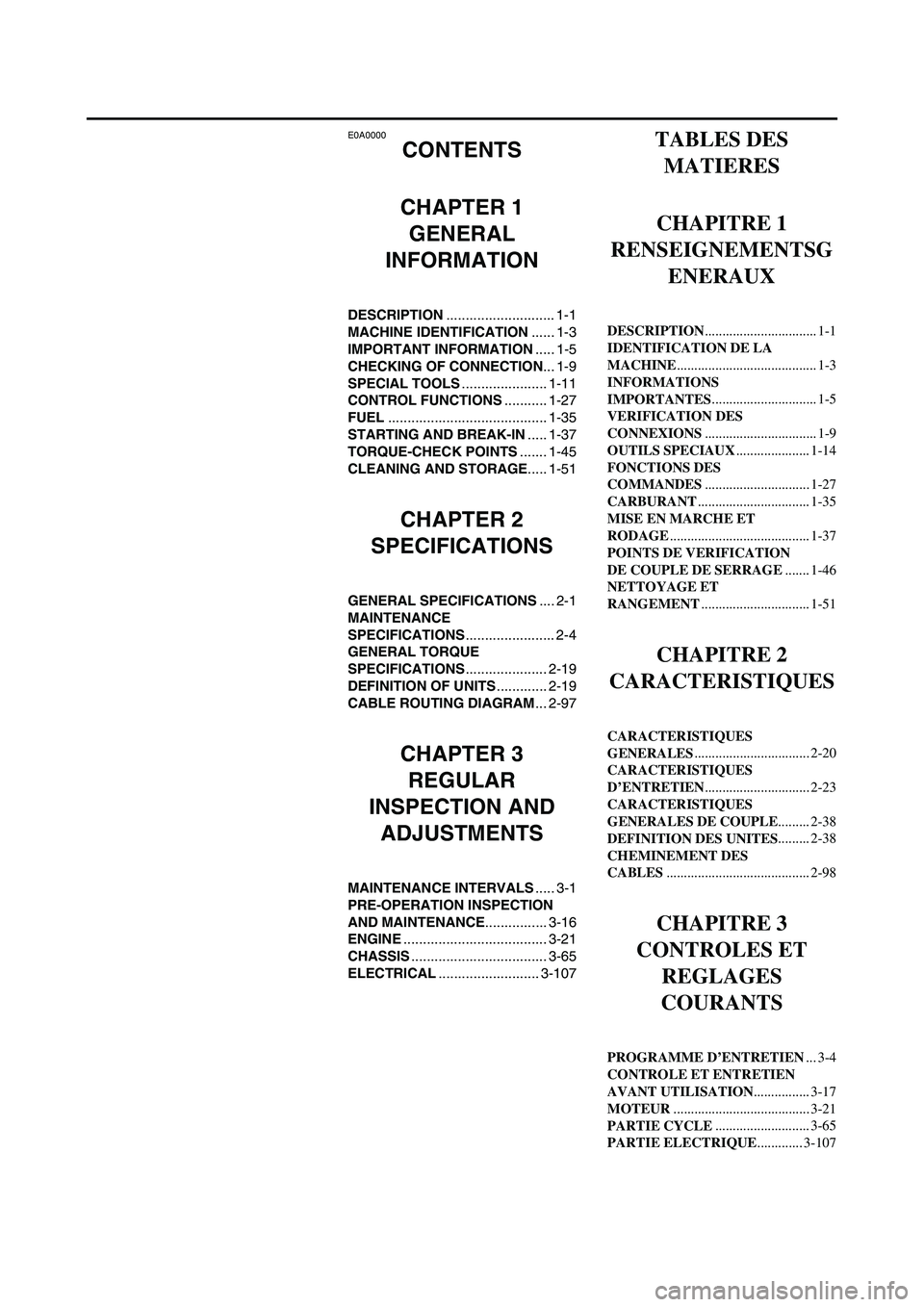
E0A0000
CONTENTS
CHAPTER 1
GENERAL
INFORMATION
DESCRIPTION............................ 1-1
MACHINE IDENTIFICATION...... 1-3
IMPORTANT INFORMATION..... 1-5
CHECKING OF CONNECTION... 1-9
SPECIAL TOOLS...................... 1-11
CONTROL FUNCTIONS........... 1-27
FUEL......................................... 1-35
STARTING AND BREAK-IN..... 1-37
TORQUE-CHECK POINTS....... 1-45
CLEANING AND STORAGE..... 1-51
CHAPTER 2
SPECIFICATIONS
GENERAL SPECIFICATIONS.... 2-1
MAINTENANCE
SPECIFICATIONS....................... 2-4
GENERAL TORQUE
SPECIFICATIONS..................... 2-19
DEFINITION OF UNITS............. 2-19
CABLE ROUTING DIAGRAM... 2-97
CHAPTER 3
REGULAR
INSPECTION AND
ADJUSTMENTS
MAINTENANCE INTERVALS..... 3-1
PRE-OPERATION INSPECTION
AND MAINTENANCE................ 3-16
ENGINE..................................... 3-21
CHASSIS................................... 3-65
ELECTRICAL.......................... 3-107
TABLES DES
MATIERES
CHAPITRE 1
RENSEIGNEMENTSG
ENERAUX
DESCRIPTION................................ 1-1
IDENTIFICATION DE LA
MACHINE........................................ 1-3
INFORMATIONS
IMPORTANTES.............................. 1-5
VERIFICATION DES
CONNEXIONS................................ 1-9
OUTILS SPECIAUX..................... 1-14
FONCTIONS DES
COMMANDES.............................. 1-27
CARBURANT................................ 1-35
MISE EN MARCHE ET
RODAGE........................................ 1-37
POINTS DE VERIFICATION
DE COUPLE DE SERRAGE....... 1-46
NETTOYAGE ET
RANGEMENT............................... 1-51
CHAPITRE 2
CARACTERISTIQUES
CARACTERISTIQUES
GENERALES................................. 2-20
CARACTERISTIQUES
D’ENTRETIEN.............................. 2-23
CARACTERISTIQUES
GENERALES DE COUPLE......... 2-38
DEFINITION DES UNITES......... 2-38
CHEMINEMENT DES
CABLES......................................... 2-98
CHAPITRE 3
CONTROLES ET
REGLAGES
COURANTS
PROGRAMME D’ENTRETIEN... 3-4
CONTROLE ET ENTRETIEN
AVANT UTILISATION................ 3-17
MOTEUR....................................... 3-21
PARTIE CYCLE........................... 3-65
PARTIE ELECTRIQUE............. 3-107