check engine YAMAHA WR 250F 2015 User Guide
[x] Cancel search | Manufacturer: YAMAHA, Model Year: 2015, Model line: WR 250F, Model: YAMAHA WR 250F 2015Pages: 430, PDF Size: 14.14 MB
Page 50 of 430

TORQUE-CHECK POINTS
1-36
EAS2GB2059
TORQUE-CHECK POINTS
Frame construction Frame to rear frame
Frame to engine protector
Combined seat and fuel tank Fuel tank to frame
Engine mounting Frame to engine
Engine bracket to engine
Engine bracket to frame
Seat Seat to frame
Steering Steering stem to handlebar Steering stem to frame
Steering stem to upper bracket
Upper bracket to handlebar
Suspension Front Steering stem to front fork Front fork to upper bracket
Front fork to lower bracket
Rear Link Assembly of links
Link to frame
Link to rear shock absorber
Link to swingarm
Mounting of rear shock absorber Rear shock absorber and frame
Mounting of swingarm Tightening of pivot shaft
Wheel (s) Mounting of wheel Front Tightening of wheel axle
Tightening of axle holder
Tightening of spoke nipple
Rear Tightening of wheel axle
Wheel to rear wheel sprocket
Tightening of spoke nipple
Brake(s) Front Brake caliper to front fork
Brake disc to wheel
Tightening of union bolt
Brake master cylinder to handle-
bar
Tightening of bleed screw
Tightening of brake hose holder
Rear Brake pedal to frame
Brake disc to wheel
Tightening of union bolt
Brake master cylinder to frame
Tightening of bleed screw
Tightening of brake hose holder
Shift pedal Shift pedal to shift shaft
Page 54 of 430

MOTORCYCLE CARE AND STORAGE
1-40
e. Remove the spark plug cap from the spark
plug, and then install the spark plug and the
spark plug cap. WARNING! To prevent
damage or injury from sparking, make
sure to ground the spark plug electrodes
while turning the engine over.
▲▲▲▲▲▲▲▲▲▲▲▲▲▲▲▲▲▲▲▲▲▲▲▲▲▲▲▲▲▲▲▲
4. Lubricate all control cables and the pivoting
points of all levers and pedals as well as of
the sidestand/ centerstand.
5. Check and, if necessary, correct the tire air
pressure, and then lift the motorcycle so that
both of its wheels are off the ground. Alter-
natively, turn the wheels a little every month
in order to prevent the tires from becoming
degraded in one spot.
6. Cover the muffler outlet with a plastic bag to
prevent moisture from entering it.
7. Remove the battery and fully charge it. Store
it in a cool, dry place and charge it once a
month. Do not store the battery in an exces-
sively cold or warm place [less than 0 °C (30
°F) or more than 30 °C (90 °F)]. For more in-
formation on storing the battery, See page
9-69.
TIP
Make any necessary repairs before storing the
motorcycle.
Page 69 of 430

TIGHTENING TORQUES
2-14
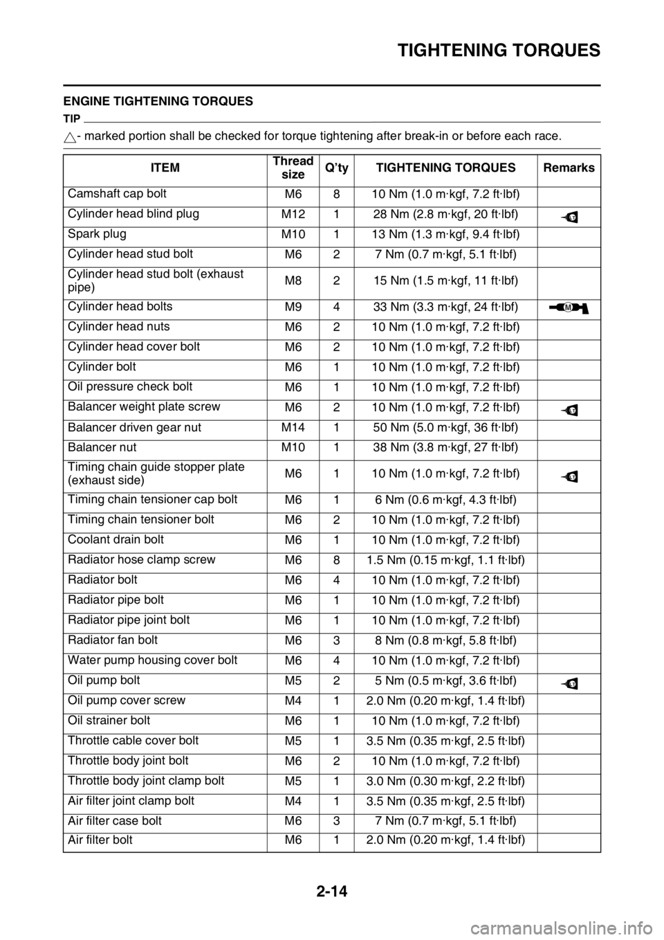
EAS2GB2068ENGINE TIGHTENING TORQUES
TIP
- marked portion shall be checked for torque tightening after break-in or before each race.
ITEMThread
sizeQ’ty TIGHTENING TORQUES Remarks
Camshaft cap bolt
M6 8 10 Nm (1.0 m·kgf, 7.2 ft·lbf)
Cylinder head blind plug
M12 1 28 Nm (2.8 m·kgf, 20 ft·lbf)
Spark plug
M10 1 13 Nm (1.3 m·kgf, 9.4 ft·lbf)
Cylinder head stud bolt
M6 2 7 Nm (0.7 m·kgf, 5.1 ft·lbf)
Cylinder head stud bolt (exhaust
pipe)M8 2 15 Nm (1.5 m·kgf, 11 ft·lbf)
Cylinder head bolts
M9 4 33 Nm (3.3 m·kgf, 24 ft·lbf)
Cylinder head nuts
M6 2 10 Nm (1.0 m·kgf, 7.2 ft·lbf)
Cylinder head cover bolt
M6 2 10 Nm (1.0 m·kgf, 7.2 ft·lbf)
Cylinder bolt
M6 1 10 Nm (1.0 m·kgf, 7.2 ft·lbf)
Oil pressure check bolt
M6 1 10 Nm (1.0 m·kgf, 7.2 ft·lbf)
Balancer weight plate screw
M6 2 10 Nm (1.0 m·kgf, 7.2 ft·lbf)
Balancer driven gear nut M14 1 50 Nm (5.0 m·kgf, 36 ft·lbf)
Balancer nut M10 1 38 Nm (3.8 m·kgf, 27 ft·lbf)
Timing chain guide stopper plate
(exhaust side)M6 1 10 Nm (1.0 m·kgf, 7.2 ft·lbf)
Timing chain tensioner cap bolt
M6 1 6 Nm (0.6 m·kgf, 4.3 ft·lbf)
Timing chain tensioner bolt
M6 2 10 Nm (1.0 m·kgf, 7.2 ft·lbf)
Coolant drain bolt
M6 1 10 Nm (1.0 m·kgf, 7.2 ft·lbf)
Radiator hose clamp screw
M6 8 1.5 Nm (0.15 m·kgf, 1.1 ft·lbf)
Radiator bolt
M6 4 10 Nm (1.0 m·kgf, 7.2 ft·lbf)
Radiator pipe bolt
M6 1 10 Nm (1.0 m·kgf, 7.2 ft·lbf)
Radiator pipe joint bolt
M6 1 10 Nm (1.0 m·kgf, 7.2 ft·lbf)
Radiator fan bolt
M6 3 8 Nm (0.8 m·kgf, 5.8 ft·lbf)
Water pump housing cover bolt
M6 4 10 Nm (1.0 m·kgf, 7.2 ft·lbf)
Oil pump bolt
M5 2 5 Nm (0.5 m·kgf, 3.6 ft·lbf)
Oil pump cover screw
M4 1 2.0 Nm (0.20 m·kgf, 1.4 ft·lbf)
Oil strainer bolt
M6 1 10 Nm (1.0 m·kgf, 7.2 ft·lbf)
Throttle cable cover bolt
M5 1 3.5 Nm (0.35 m·kgf, 2.5 ft·lbf)
Throttle body joint bolt
M6 2 10 Nm (1.0 m·kgf, 7.2 ft·lbf)
Throttle body joint clamp bolt
M5 1 3.0 Nm (0.30 m·kgf, 2.2 ft·lbf)
Air filter joint clamp bolt
M4 1 3.5 Nm (0.35 m·kgf, 2.5 ft·lbf)
Air filter case bolt M6 3 7 Nm (0.7 m·kgf, 5.1 ft·lbf)
Air filter bolt M6 1 2.0 Nm (0.20 m·kgf, 1.4 ft·lbf)
LT
M
LT
LT
LT
Page 72 of 430

TIGHTENING TORQUES
2-17
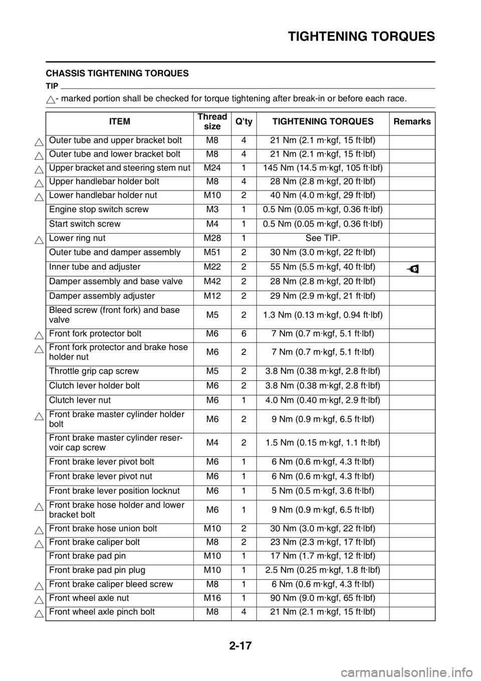
EAS2GB2069CHASSIS TIGHTENING TORQUES
TIP
- marked portion shall be checked for torque tightening after break-in or before each race.
ITEMThread
sizeQ’ty TIGHTENING TORQUES Remarks
Outer tube and upper bracket bolt M8 4 21 Nm (2.1 m·kgf, 15 ft·lbf)
Outer tube and lower bracket bolt M8 4 21 Nm (2.1 m·kgf, 15 ft·lbf)
Upper bracket and steering stem nut M24 1 145 Nm (14.5 m·kgf, 105 ft·lbf)
Upper handlebar holder bolt M8 4 28 Nm (2.8 m·kgf, 20 ft·lbf)
Lower handlebar holder nut M10 2 40 Nm (4.0 m·kgf, 29 ft·lbf)
Engine stop switch screw M3 1 0.5 Nm (0.05 m·kgf, 0.36 ft·lbf)
Start switch screw M4 1 0.5 Nm (0.05 m·kgf, 0.36 ft·lbf)
Lower ring nut M28 1 See TIP.
Outer tube and damper assembly M51 2 30 Nm (3.0 m·kgf, 22 ft·lbf)
Inner tube and adjuster M22 2 55 Nm (5.5 m·kgf, 40 ft·lbf)
Damper assembly and base valve M42 2 28 Nm (2.8 m·kgf, 20 ft·lbf)
Damper assembly adjuster M12 2 29 Nm (2.9 m·kgf, 21 ft·lbf)
Bleed screw (front fork) and base
valveM5 2 1.3 Nm (0.13 m·kgf, 0.94 ft·lbf)
Front fork protector bolt M6 6 7 Nm (0.7 m·kgf, 5.1 ft·lbf)
Front fork protector and brake hose
holder nutM6 2 7 Nm (0.7 m·kgf, 5.1 ft·lbf)
Throttle grip cap screw M5 2 3.8 Nm (0.38 m·kgf, 2.8 ft·lbf)
Clutch lever holder bolt M6 2 3.8 Nm (0.38 m·kgf, 2.8 ft·lbf)
Clutch lever nut M6 1 4.0 Nm (0.40 m·kgf, 2.9 ft·lbf)
Front brake master cylinder holder
boltM6 2 9 Nm (0.9 m·kgf, 6.5 ft·lbf)
Front brake master cylinder reser-
voir cap screwM4 2 1.5 Nm (0.15 m·kgf, 1.1 ft·lbf)
Front brake lever pivot bolt M6 1 6 Nm (0.6 m·kgf, 4.3 ft·lbf)
Front brake lever pivot nut M6 1 6 Nm (0.6 m·kgf, 4.3 ft·lbf)
Front brake lever position locknut M6 1 5 Nm (0.5 m·kgf, 3.6 ft·lbf)
Front brake hose holder and lower
bracket boltM6 1 9 Nm (0.9 m·kgf, 6.5 ft·lbf)
Front brake hose union bolt M10 2 30 Nm (3.0 m·kgf, 22 ft·lbf)
Front brake caliper bolt M8 2 23 Nm (2.3 m·kgf, 17 ft·lbf)
Front brake pad pin M10 1 17 Nm (1.7 m·kgf, 12 ft·lbf)
Front brake pad pin plug M10 1 2.5 Nm (0.25 m·kgf, 1.8 ft·lbf)
Front brake caliper bleed screw M8 1 6 Nm (0.6 m·kgf, 4.3 ft·lbf)
Front wheel axle nut M16 1 90 Nm (9.0 m·kgf, 65 ft·lbf)
Front wheel axle pinch bolt M8 4 21 Nm (2.1 m·kgf, 15 ft·lbf)
LT
Page 103 of 430

3
PERIODIC CHECKS AND ADJUSTMENTS
PERIODIC MAINTENANCE............................................................................. 3-1
INTRODUCTION ........................................................................................ 3-1
PERIODIC MAINTENANCE CHART FOR THE EMISSION
CONTROL SYSTEM ................................................................................. 3-1
GENERAL MAINTENANCE AND LUBRICATION CHART ........................ 3-2
MAINTENANCE INTERVALS FOR COMPETITION USE ......................... 3-4
PRE-OPERATION INSPECTION AND MAINTENANCE................................. 3-9
GENERAL INSPECTION AND MAINTENANCE........................................ 3-9
ENGINE.......................................................................................................... 3-10
CHECKING THE COOLANT LEVEL ........................................................ 3-10
CHECKING THE COOLING SYSTEM ..................................................... 3-10
CHANGING THE COOLANT.................................................................... 3-10
CHECKING THE RADIATOR CAP .......................................................... 3-11
CHECKING THE RADIATOR CAP OPENING PRESSURE .................... 3-11
CHECKING THE COOLANT CIRCULATORY SYSTEM FOR LEAKS .... 3-12
ADJUSTING THE CLUTCH LEVER FREE PLAY .................................... 3-12
ADJUSTING THE THROTTLE GRIP FREE PLAY .................................. 3-13
LUBRICATING THE THROTTLE CABLE ................................................ 3-13
CLEANING THE AIR FILTER ELEMENT................................................. 3-14
CHECKING THE THROTTLE BODY JOINT ............................................ 3-15
CHECKING THE BREATHER HOSES .................................................... 3-15
CHECKING THE EXHAUST SYSTEM..................................................... 3-15
CHECKING THE FUEL LINE ................................................................... 3-16
CHECKING THE ENGINE OIL LEVEL..................................................... 3-16
CHANGING THE ENGINE OIL ................................................................ 3-17
ADJUSTING THE ENGINE IDLING SPEED ............................................ 3-18
ADJUSTING THE VALVE CLEARANCE ................................................. 3-19
CLEANING THE SPARK ARRESTER ..................................................... 3-23
CHASSIS........................................................................................................ 3-24
BLEEDING THE BRAKE SYSTEM .......................................................... 3-24
CHECKING THE BRAKE HOSE .............................................................. 3-25
ADJUSTING THE FRONT BRAKE .......................................................... 3-25
ADJUSTING THE REAR BRAKE ............................................................. 3-26
CHECKING THE FRONT BRAKE PADS ................................................. 3-26
CHECKING THE REAR BRAKE PADS ................................................... 3-28
CHECKING THE REAR BRAKE PAD INSULATOR ................................ 3-29
CHECKING THE BRAKE FLUID LEVEL.................................................. 3-29
ADJUSTING THE DRIVE CHAIN SLACK ................................................ 3-30
CHECKING THE FRONT FORK LEGS ................................................... 3-31
CHECKING THE FRONT FORK PROTECTOR GUIDE .......................... 3-31
CLEANING THE FRONT FORK OIL SEAL AND DUST SEAL ................ 3-31
AIR BLEEDING FROM FRONT FORK .................................................... 3-31
ADJUSTING THE FRONT FORK LEGS .................................................. 3-32
CHECKING THE SWINGARM OPERATION ........................................... 3-33
CHECKING THE REAR SUSPENSION ................................................... 3-33
Page 105 of 430

PERIODIC MAINTENANCE
3-1
EAS2GB2076
PERIODIC MAINTENANCE
EAS2GB2077INTRODUCTION
This chapter includes all information necessary to perform recommended checks and adjustments.
If followed, these preventive maintenance procedures will ensure more reliable vehicle operation, a
longer service life and reduce the need for costly overhaul work. This information applies to vehicles
already in service as well as to new vehicles that are being prepared for sale. All service technicians
should be familiar with this entire chapter.
EAS2GB2078PERIODIC MAINTENANCE CHART FOR THE EMISSION CONTROL SYSTEM
TIP
• From 4200 mi (7000 km) or 9 months, repeat the maintenance intervals starting from 1800 mi (3000
km) or 3 months.
• Items marked with an asterisk should be performed by a Yamaha dealer as they require special
tools, data and technical skills.
NO. ITEM CHECKS AND MAINTENANCE JOBSINITIALODOMETER READ-
INGS
600 mi
(1000
km) or 1
month1800 mi
(3000
km) or 3
months3000 mi
(5000
km) or 6
months
1*Fuel line• Check fuel hoses for cracks or dam-
age.
• Replace if necessary.
2Spark plug• Check condition.
• Adjust gap and clean.
3*Valve clear-
ance• Check and adjust valve clearance
when engine is cold.
4*Air filter ele-
ment• Clean with solvent and apply foam air-
filter oil or equivalent oil.
• Replace if necessary.
5*Breather sys-
tem• Check ventilation hose for cracks or
damage and drain any deposits.
• Replace. Every 2 years
6*Fuel injec-
tion• Adjust engine idling speed.
7Exhaust sys-
tem• Check for leakage.
• Tighten if necessary.
• Replace gasket(s) if necessary.
8Engine oil• Change (warm engine before drain-
ing).
9Engine oil fil-
ter element• Replace.
10Engine oil
strainer• Clean.
Page 107 of 430

PERIODIC MAINTENANCE
3-3
TIP
• The air filter needs more frequent service if you are riding in unusually wet or dusty areas.
• Hydraulic brake service
• After disassembling the brake master cylinders and calipers, always change the fluid. Regularly
check the brake fluid levels and fill the reservoirs as required.
• Every two years replace the internal components of the brake master cylinders and calipers, and
change the brake fluid.
• Replace the brake hoses every four years and if cracked or damaged.
13
Brake and
clutch lever
pivot shafts• Apply lithium-soap-based grease (all-
purpose grease) lightly.
14Brake pedal
pivot shafts• Apply lithium-soap-based grease (all-
purpose grease) lightly.
15Sidestand
pivot• Check operation.
• Apply lithium-soap-based grease (all-
purpose grease) lightly.
16*Front fork• Check operation and for oil leakage.
• Replace if necessary.
17*Shock ab-
sorber as-
sembly• Check operation and for oil leakage.
• Replace if necessary.
18*Rear suspen-
sion link piv-
ots• Apply molybdenum disulfide grease
lightly.
19*Control ca-
bles• Apply Yamaha chain and cable lube or
engine oil 10W-30 thoroughly.
20*Throttle grip
housing and
cable• Check operation and free play.
• Adjust the throttle cable free play if
necessary.
• Lubricate the throttle grip housing and
cable.
21*Chassis fas-
teners• Check all chassis fitting and fasteners.
• Correct if necessary.
22Battery• Check terminal for looseness and cor-
rosion. NO. ITEM CHECKS AND MAINTENANCE JOBSINITIALODOMETER READ-
INGS
600 mi
(1000
km) or 1
month1800 mi
(3000
km) or 3
months3000 mi
(5000
km) or 6
months
Page 108 of 430

PERIODIC MAINTENANCE
3-4
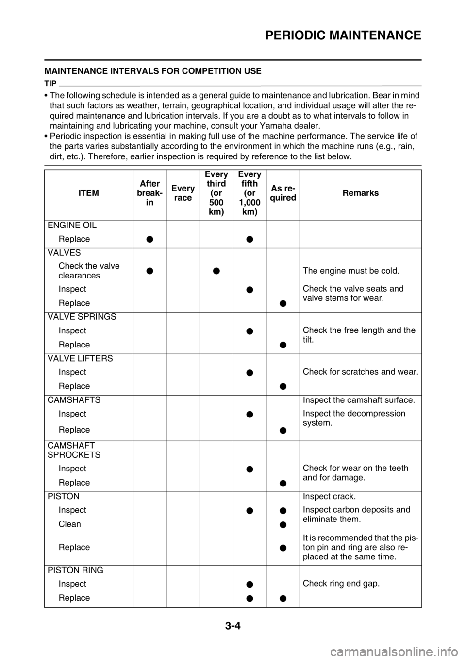
EAS2GB2080MAINTENANCE INTERVALS FOR COMPETITION USE
TIP
• The following schedule is intended as a general guide to maintenance and lubrication. Bear in mind
that such factors as weather, terrain, geographical location, and individual usage will alter the re-
quired maintenance and lubrication intervals. If you are a doubt as to what intervals to follow in
maintaining and lubricating your machine, consult your Yamaha dealer.
• Periodic inspection is essential in making full use of the machine performance. The service life of
the parts varies substantially according to the environment in which the machine runs (e.g., rain,
dirt, etc.). Therefore, earlier inspection is required by reference to the list below.
ITEMAfter
break-
inEvery
raceEvery
third
(or
500
km)Every
fifth
(or
1,000
km)As re-
quiredRemarks
ENGINE OIL
Replace
VALVES
Check the valve
clearancesThe engine must be cold.
InspectCheck the valve seats and
valve stems for wear.
Replace
VALVE SPRINGS
InspectCheck the free length and the
tilt.
Replace
VALVE LIFTERS
InspectCheck for scratches and wear.
Replace
CAMSHAFTS Inspect the camshaft surface.
InspectInspect the decompression
system.
Replace
CAMSHAFT
SPROCKETS
InspectCheck for wear on the teeth
and for damage.
Replace
PISTON Inspect crack.
InspectInspect carbon deposits and
eliminate them.
Clean
ReplaceIt is recommended that the pis-
ton pin and ring are also re-
placed at the same time.
PISTON RING
InspectCheck ring end gap.
Replace
Page 110 of 430

PERIODIC MAINTENANCE
3-6
COOLING SYSTEM
Check coolant lev-
el and leakage
Check radiator cap
operation
Replace coolant Every two years
Inspect hoses
OUTSIDE NUTS
AND BOLTS
RetightenRefer to “STARTING AND
BREAK-IN” on page 1-32.
AIR FILTER
Clean and lubri-
cateUse foam air-filter oil or equiv-
alent oil.
Replace
OIL FILTER
Replace
ENGINE GUARD
Replace Breakage
FRAME
Clean and inspect
FUEL TANK, FUEL
PUMP
Clean and inspect
FUEL HOSE
Inspect
Replace Every four yearsITEMAfter
break-
inEvery
raceEvery
third
(or
500
km)Every
fifth
(or
1,000
km)As re-
quiredRemarks
Page 113 of 430

PRE-OPERATION INSPECTION AND MAINTENANCE
3-9
EAS2GB2081
PRE-OPERATION INSPECTION AND MAINTENANCE
Before riding for break-in operation, practice or a race, make sure the machine is in good operating
condition.
Before using this machine, check the following points.
EAS2GB2082GENERAL INSPECTION AND MAINTENANCE
TIP
Perform usual maintenance enough so that, in the race course, a confirmation of that and simple set-
ting adjustments may only be left, in order to get enough time to use effectively.ITEM inspect Page
CoolantCheck that coolant is filled up to the radiator cap.
Check the cooling system for leakage.3-10 – 12
FuelCheck that a fresh gasoline is filled in the fuel tank.
Check the fuel line for leakage.1-32
Engine oilCheck that the oil level is correct. Check the crank-
case and oil line for leakage.3-16 – 18
Gear shifter and clutchCheck that gears can be shifted correctly in order and
that the clutch operates smoothly.3-12 – 13
Throttle grip/HousingCheck that the throttle grip operation and free play
are correctly adjusted. Lubricate the throttle grip and
housing, if necessary.3-13 – 14
BrakesCheck the play of front brake and effect of front and
rear brake.3-24 – 30
Drive chainCheck drive chain slack and alignment. Check that
the drive chain is lubricated properly.3-30
5-68 – 69
WheelsCheck for excessive wear and tire pressure. Check
for loose spokes and have no excessive play.3-35 – 36
SteeringCheck that the handlebar can be turned smoothly and
have no excessive play.3-36 – 37
Front forks and rear
shock absorberCheck that they operate smoothly and there is no oil
leakage.3-31 – 35
Cables (wires)Check that the clutch and throttle cables move
smoothly. Check that they are not caught when the
handlebars are turned or when the front forks travel
up and down.—
Exhaust pipeCheck that the exhaust pipe is tightly mounted and
has no cracks.3-15 – 16
Rear wheel sprocketCheck that the rear wheel sprocket tightening bolt is
not loose.5-10 – 11
LubricationCheck for smooth operation. Lubricate if necessary. 3-13
3-37 – 38
Bolts and nutsCheck the chassis and engine for loose bolts and
nuts.1-36 – 37
Lead connectorsCheck that the AC magneto, ECU and ignition coil are
connected tightly.1-11 – 14
SettingsIs the machine set suitably for the condition of the rac-
ing course and weather or by taking into account the
results of test runs before racing? Are inspection and
maintenance completely done?4-1 – 8