check engine YAMAHA WR 250F 2015 Service Manual
[x] Cancel search | Manufacturer: YAMAHA, Model Year: 2015, Model line: WR 250F, Model: YAMAHA WR 250F 2015Pages: 430, PDF Size: 14.14 MB
Page 249 of 430
CYLINDER HEAD
6-18
EAS2GB2246
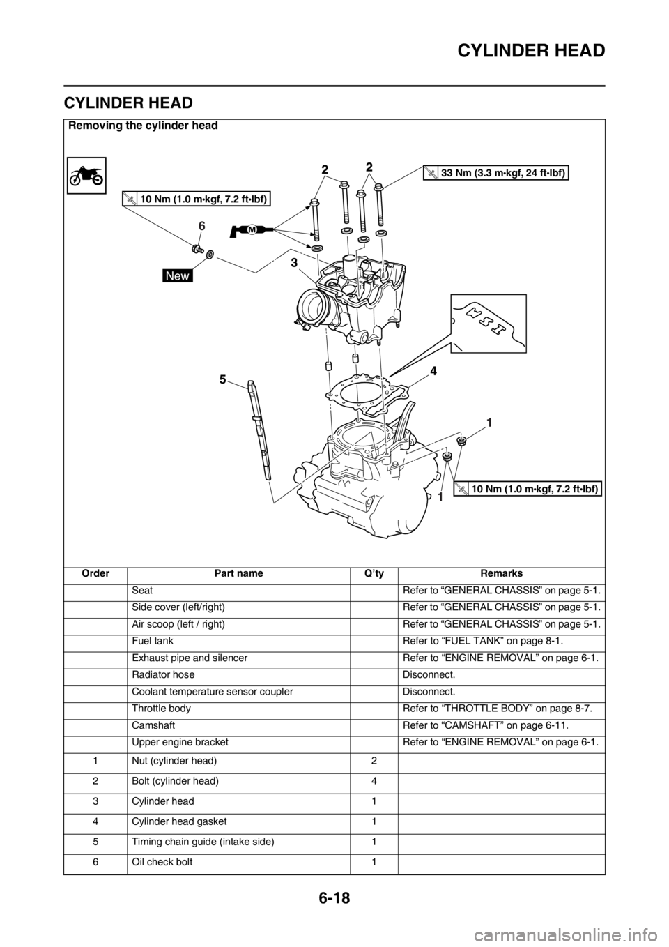
CYLINDER HEAD
Removing the cylinder head
Order Part name Q’ty Remarks
Seat Refer to “GENERAL CHASSIS” on page 5-1.
Side cover (left/right) Refer to “GENERAL CHASSIS” on page 5-1.
Air scoop (left / right) Refer to “GENERAL CHASSIS” on page 5-1.
Fuel tank Refer to “FUEL TANK” on page 8-1.
Exhaust pipe and silencer Refer to “ENGINE REMOVAL” on page 6-1.
Radiator hose Disconnect.
Coolant temperature sensor coupler Disconnect.
Throttle body Refer to “THROTTLE BODY” on page 8-7.
Camshaft Refer to “CAMSHAFT” on page 6-11.
Upper engine bracket Refer to “ENGINE REMOVAL” on page 6-1.
1 Nut (cylinder head) 2
2 Bolt (cylinder head) 4
3 Cylinder head 1
4 Cylinder head gasket 1
5 Timing chain guide (intake side) 1
6 Oil check bolt 1
6
10 Nm (1.0 m kgf, 7.2 ft Ibf)T.R.
33 Nm (3.3 m kgf, 24 ft Ibf)T.R.
10 Nm (1.0 m kgf, 7.2 ft Ibf)T.R.
Page 264 of 430
CYLINDER AND PISTON
6-33
EAS2GB2262CHECKING THE PISTON PIN
1. Check:
• Piston pin
Blue discoloration/grooves Replace the
piston pin and then check the lubrication
system.
2. Measure:
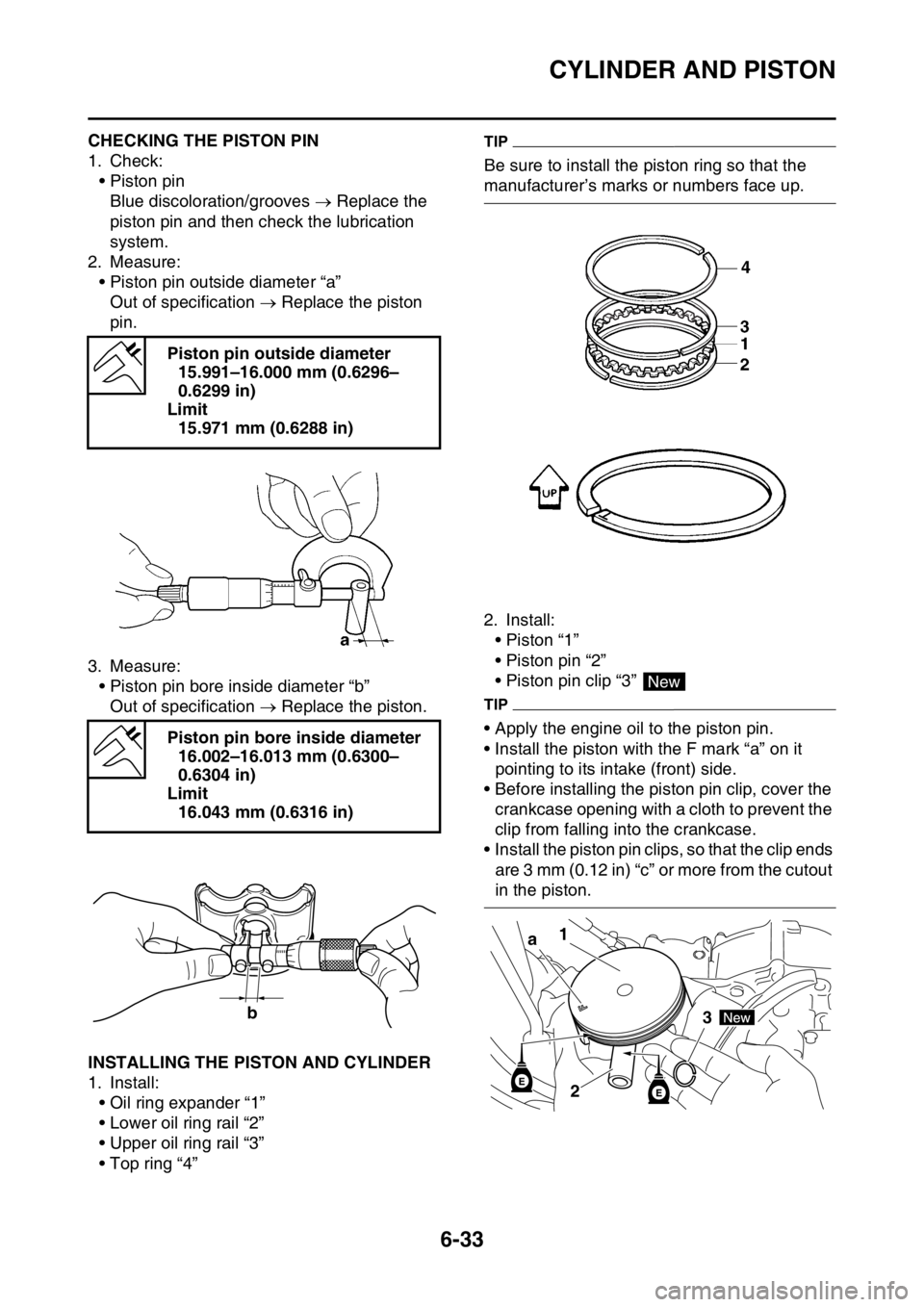
• Piston pin outside diameter “a”
Out of specification Replace the piston
pin.
3. Measure:
• Piston pin bore inside diameter “b”
Out of specification Replace the piston.
EAS2GB2263INSTALLING THE PISTON AND CYLINDER
1. Install:
• Oil ring expander “1”
• Lower oil ring rail “2”
• Upper oil ring rail “3”
• Top ring “4”
TIP
Be sure to install the piston ring so that the
manufacturer’s marks or numbers face up.
2. Install:
• Piston “1”
• Piston pin “2”
• Piston pin clip “3”
TIP
• Apply the engine oil to the piston pin.
• Install the piston with the F mark “a” on it
pointing to its intake (front) side.
• Before installing the piston pin clip, cover the
crankcase opening with a cloth to prevent the
clip from falling into the crankcase.
• Install the piston pin clips, so that the clip ends
are 3 mm (0.12 in) “c” or more from the cutout
in the piston. Piston pin outside diameter
15.991–16.000 mm (0.6296–
0.6299 in)
Limit
15.971 mm (0.6288 in)
Piston pin bore inside diameter
16.002–16.013 mm (0.6300–
0.6304 in)
Limit
16.043 mm (0.6316 in)
b
4
New
1
3
2 a
Page 276 of 430
CLUTCH
6-45
EAS2GB2278CHECKING THE PRIMARY DRIVEN GEAR
1. Check:
• Primary driven gear
Damage/wear Replace the primary drive
and primary driven gears as a set.
Excessive noise during operation Re-
place the primary drive and primary driven
gears as a set.
EAS2GB2279INSTALLING THE OIL SEAL
1. Install:
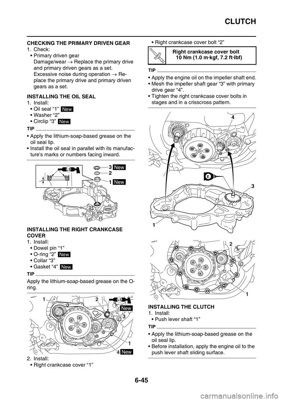
• Oil seal “1”
• Washer “2”
• Circlip “3”
TIP
• Apply the lithium-soap-based grease on the
oil seal lip.
• Install the oil seal in parallel with its manufac-
ture's marks or numbers facing inward.
EAS2GB2280INSTALLING THE RIGHT CRANKCASE
COVER
1. Install:
• Dowel pin “1”
• O-ring “2”
• Collar “3”
• Gasket “4”
TIP
Apply the lithium-soap-based grease on the O-
ring.
2. Install:
• Right crankcase cover “1”• Right crankcase cover bolt “2”
TIP
• Apply the engine oil on the impeller shaft end.
• Mesh the impeller shaft gear “3” with primary
drive gear “4”.
• Tighten the right crankcase cover bolts in
stages and in a crisscross pattern.
EAS2GB2281INSTALLING THE CLUTCH
1. Install:
• Push lever shaft “1”
TIP
• Apply the lithium-soap-based grease on the
oil seal lip.
• Before installation, apply the engine oil to the
push lever shaft sliding surface.
New
New
3
2
1
LS
New
New
1
1
3
2
4
LS
Right crankcase cover bolt
10 Nm (1.0 m·kgf, 7.2 ft·lbf)
T R..
3
1
4
E
1
2
Page 290 of 430
OIL PUMP AND BALANCER GEAR
6-59
3. Check:
• Oil pump operation
Rough movement Repeat steps (1) and
(2) or replace the defective part(s).
EAS2GB2305ASSEMBLING THE OIL PUMP
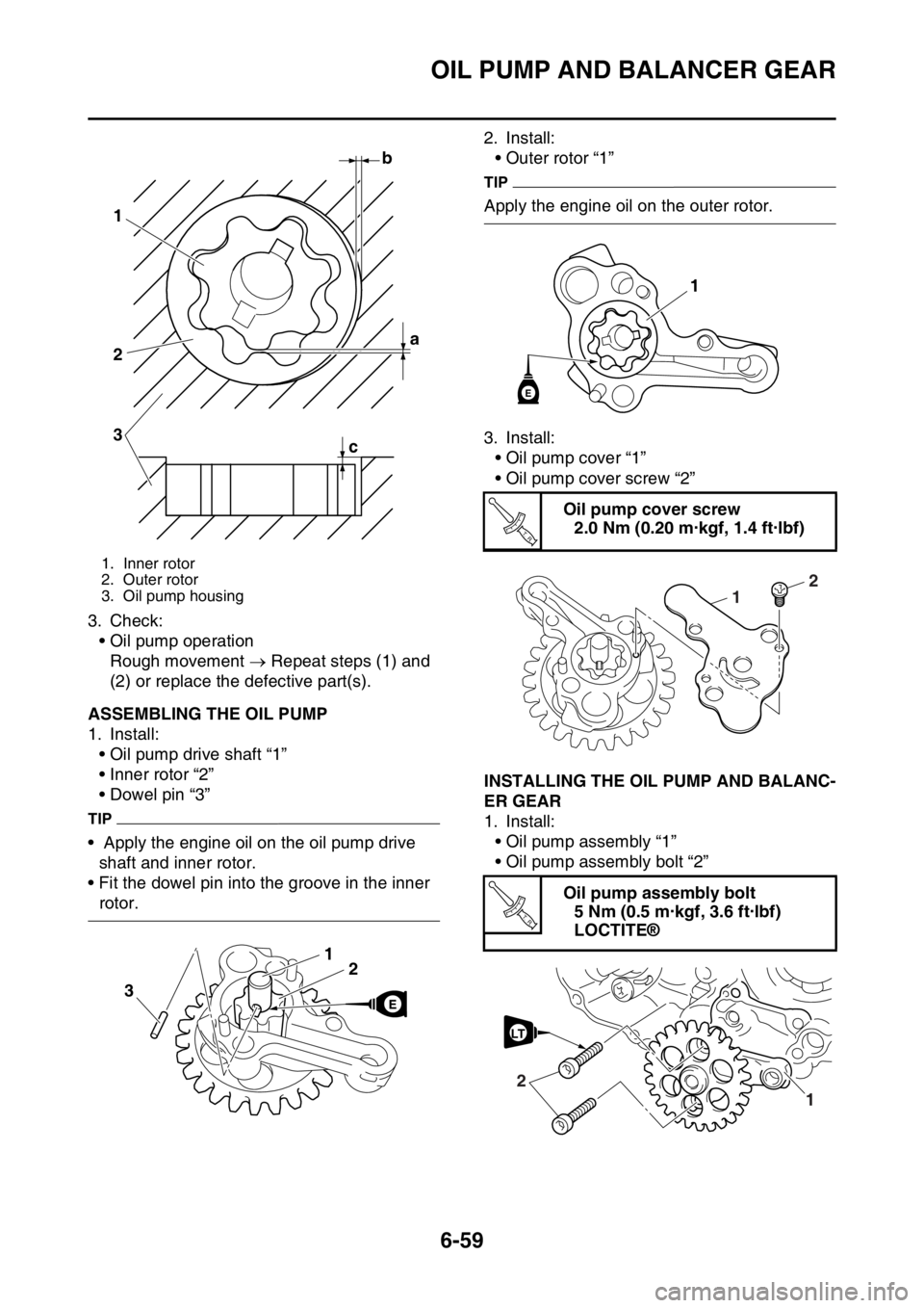
1. Install:
• Oil pump drive shaft “1”
• Inner rotor “2”
• Dowel pin “3”
TIP
• Apply the engine oil on the oil pump drive
shaft and inner rotor.
• Fit the dowel pin into the groove in the inner
rotor.2. Install:
• Outer rotor “1”
TIP
Apply the engine oil on the outer rotor.
3. Install:
• Oil pump cover “1”
• Oil pump cover screw “2”
EAS2GB2306INSTALLING THE OIL PUMP AND BALANC-
ER GEAR
1. Install:
• Oil pump assembly “1”
• Oil pump assembly bolt “2”
ECA
1. Inner rotor
2. Outer rotor
3. Oil pump housing
b
a 1
2
3
c
21
3
Oil pump cover screw
2.0 Nm (0.20 m·kgf, 1.4 ft·lbf)
Oil pump assembly bolt
5 Nm (0.5 m·kgf, 3.6 ft·lbf)
LOCTITE®
1
E
T R..
2
1
T R..
1
2
LT
Page 302 of 430

CRANKCASE
6-71
EAS2GB2313DISASSEMBLING THE CRANKCASE
1. Separate:
• Right crankcase
• Left crankcase
▼▼▼▼▼▼▼▼▼▼▼▼▼▼▼▼▼▼▼▼▼▼▼▼▼▼▼▼▼▼▼▼
a. Remove the crankcase bolts.
TIP
Loosen each bolt 1/4 of a turn at a time and af-
ter all the bolts are loosened, remove them.
b. Remove the right crankcase “1”.
TIP
• Place the crankcase with its left side down-
ward and split it by inserting a screwdriver tip
into the splitting slit “a” in the crankcase.
• Lift the right crankcase horizontally while light-
ly patting the crankcase splitting slit and the
engine mounting boss using a soft hammer,
and leave the crankshaft and the transmission
with the left crankcase.
ECA
NOTICE
Use soft hammer to tap on the case half.
Tap only on reinforced portions of case. Do
not tap on gasket mating surface. Work
slowly and carefully. Make sure the case
halves separate evenly. If the cases do not
separate, check for a remaining case bolt or
fitting. Do not force.c. Remove the dowel pins and O-ring.
▲▲▲▲▲▲▲▲▲▲▲▲▲▲▲▲▲▲▲▲▲▲▲▲▲▲▲▲▲▲▲▲
EAS2GB2314REMOVING THE CRANKCASE BEARING
1. Remove:
• Bearing “1”
TIP
• Remove the bearing from the crankcase by
pressing its inner race.
• Do not use the removed bearing.
EAS2GB2315CHECKING THE TIMING CHAIN, TIMING
CHAIN GUIDE, OIL STRAINER
1. Check:
• Timing chain
Stiffness Replace the camshaft sprocket,
timing chain and crankshaft sprocket as a
set.
2. Check:
• Timing chain guide
Damage/wear Replace
EAS2GB2316CHECKING THE CRANKCASE
1. Wash:
• Crankcase
TIP
• Wash the crankcase in a mild solvent.
• Remove any remaining gasket from the
crankcase mating surface.
2. Check:
• Crankcase
Crack/damage Replace.
1
a
Page 311 of 430

TRANSMISSION
6-80
6. Install:
• Shift fork 1 (L) “1”
• Shift fork 2 (C) “2”
• Shift fork 3 (R) “3”
• Shift cam “4”
(to the main axle and the drive axle)
TIP
• Apply engine oil to the shift fork grooves.
• Apply engine oil to the shift cam groove and
the bearing contact surface.
• Mesh the shift fork 1 (L) with the 5th wheel
gear “5” and “3” (R) with the 6th wheel gear “7”
on the drive axle.
• Mesh the shift fork 2 (C) with the 3rd/4th pin-
ion gear “6” on the main axle.7. Install:
• Long shift fork guide bar “1”
• Short shift fork guide bar “2”
• Spring “3”
TIP
• Screw the spring into the shift fork guide bar
lightly beforehand.
• Apply the engine oil on the shift fork guide
bars.
8. Check:
• Operation of shift cam and shift fork
• Transmission operation
Unsmooth operation Repair.
3
12
6
2
4
5
3
7
1
E
E
E
2 13
E
Page 319 of 430
WATER PUMP
7-6
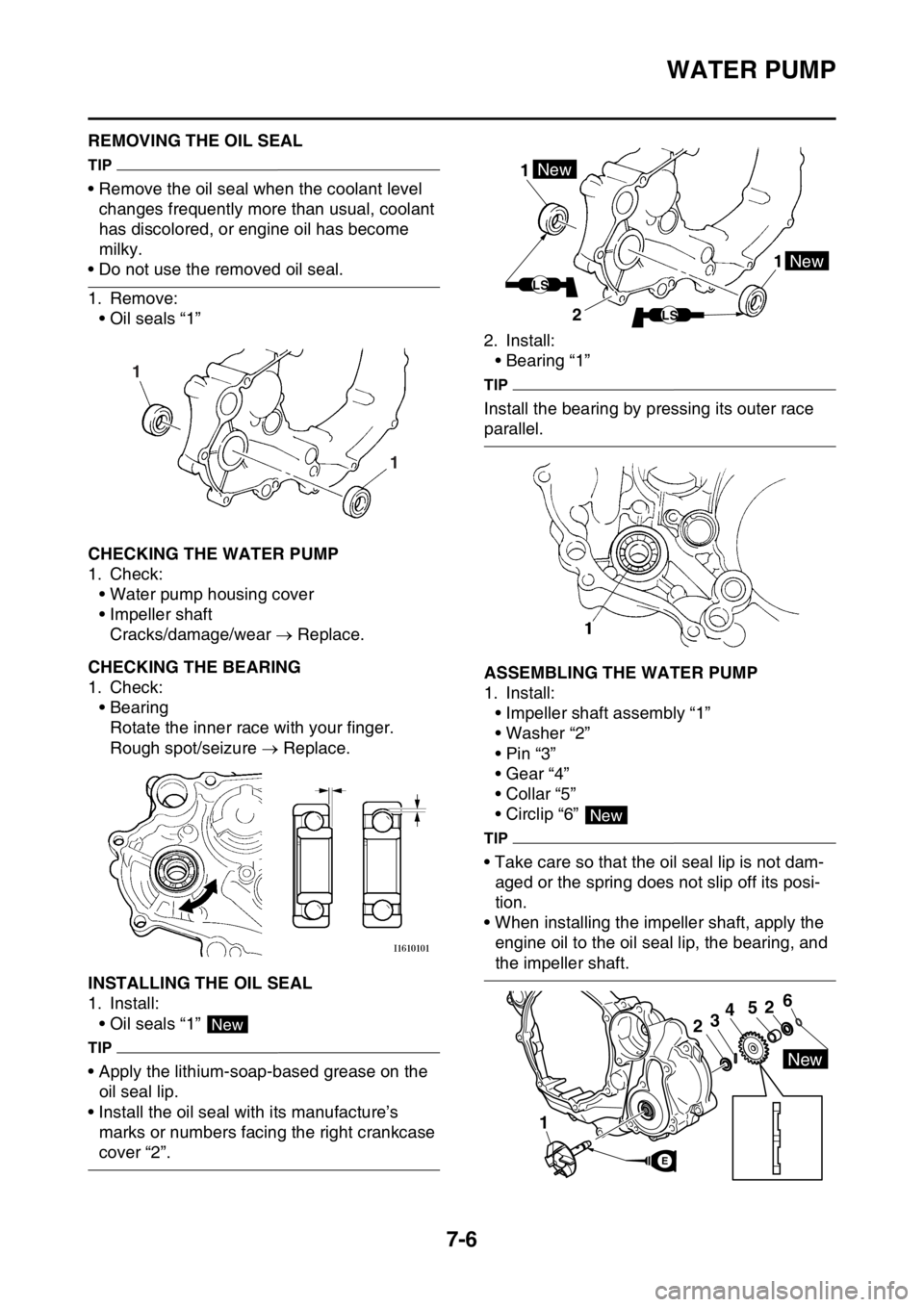
EAS2GB2335REMOVING THE OIL SEAL
TIP
• Remove the oil seal when the coolant level
changes frequently more than usual, coolant
has discolored, or engine oil has become
milky.
• Do not use the removed oil seal.
1. Remove:
• Oil seals “1”
EAS2GB2336CHECKING THE WATER PUMP
1. Check:
• Water pump housing cover
• Impeller shaft
Cracks/damage/wear Replace.
EAS2GB2337CHECKING THE BEARING
1. Check:
• Bearing
Rotate the inner race with your finger.
Rough spot/seizure Replace.
EAS2GB2338INSTALLING THE OIL SEAL
1. Install:
• Oil seals “1”
TIP
• Apply the lithium-soap-based grease on the
oil seal lip.
• Install the oil seal with its manufacture’s
marks or numbers facing the right crankcase
cover “2”.2. Install:
• Bearing “1”
TIP
Install the bearing by pressing its outer race
parallel.
EAS2GB2339ASSEMBLING THE WATER PUMP
1. Install:
• Impeller shaft assembly “1”
• Washer “2”
•Pin “3”
• Gear “4”
• Collar “5”
• Circlip “6”
TIP
• Take care so that the oil seal lip is not dam-
aged or the spring does not slip off its posi-
tion.
• When installing the impeller shaft, apply the
engine oil to the oil seal lip, the bearing, and
the impeller shaft.
1 1
New
1 1New
New
LS
LS2
New
1
2
52346
New
E
Page 326 of 430
FUEL TANK
8-5
TIP
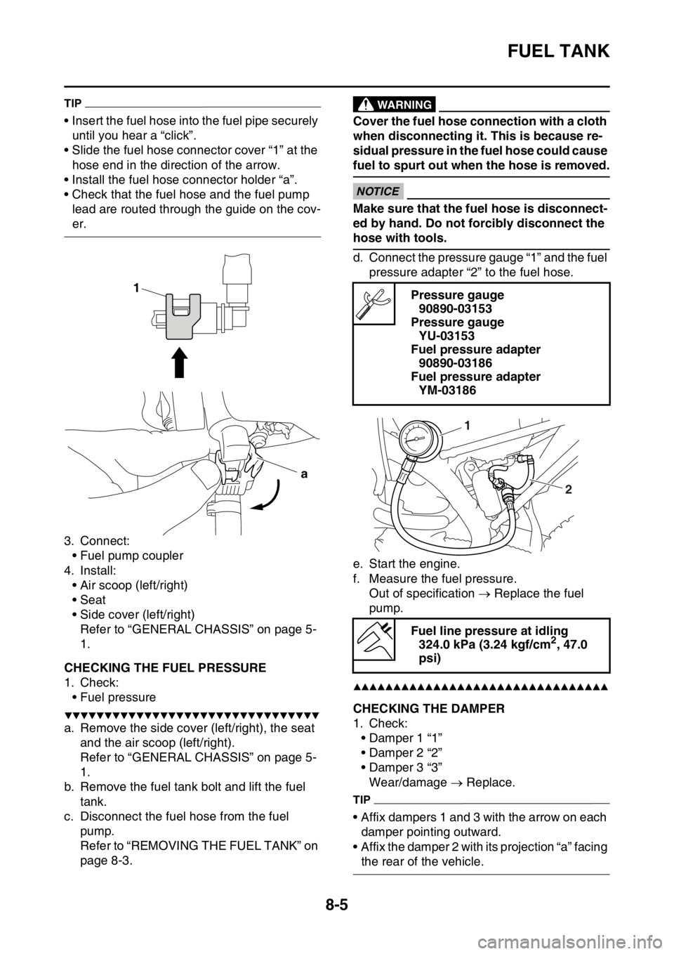
• Insert the fuel hose into the fuel pipe securely
until you hear a “click”.
• Slide the fuel hose connector cover “1” at the
hose end in the direction of the arrow.
• Install the fuel hose connector holder “a”.
• Check that the fuel hose and the fuel pump
lead are routed through the guide on the cov-
er.
3. Connect:
• Fuel pump coupler
4. Install:
• Air scoop (left/right)
• Seat
• Side cover (left/right)
Refer to “GENERAL CHASSIS” on page 5-
1.
EAS2GB2350CHECKING THE FUEL PRESSURE
1. Check:
• Fuel pressure
▼▼▼▼▼▼▼▼▼▼▼▼▼▼▼▼▼▼▼▼▼▼▼▼▼▼▼▼▼▼▼▼
a. Remove the side cover (left/right), the seat
and the air scoop (left/right).
Refer to “GENERAL CHASSIS” on page 5-
1.
b. Remove the fuel tank bolt and lift the fuel
tank.
c. Disconnect the fuel hose from the fuel
pump.
Refer to “REMOVING THE FUEL TANK” on
page 8-3.
EWA
WARNING
Cover the fuel hose connection with a cloth
when disconnecting it. This is because re-
sidual pressure in the fuel hose could cause
fuel to spurt out when the hose is removed.
ECA
NOTICE
Make sure that the fuel hose is disconnect-
ed by hand. Do not forcibly disconnect the
hose with tools.
d. Connect the pressure gauge “1” and the fuel
pressure adapter “2” to the fuel hose.
e. Start the engine.
f. Measure the fuel pressure.
Out of specification Replace the fuel
pump.
▲▲▲▲▲▲▲▲▲▲▲▲▲▲▲▲▲▲▲▲▲▲▲▲▲▲▲▲▲▲▲▲
EAS2GB2351CHECKING THE DAMPER
1. Check:
• Damper 1 “1”
• Damper 2 “2”
• Damper 3 “3”
Wear/damage Replace.
TIP
• Affix dampers 1 and 3 with the arrow on each
damper pointing outward.
• Affix the damper 2 with its projection “a” facing
the rear of the vehicle.
1
a
Pressure gauge
90890-03153
Pressure gauge
YU-03153
Fuel pressure adapter
90890-03186
Fuel pressure adapter
YM-03186
Fuel line pressure at idling
324.0 kPa (3.24 kgf/cm
2, 47.0
psi)
1
2
Page 331 of 430
THROTTLE BODY
8-10
EAS2GB2354CHECKING THE INJECTOR
1. Check:
• Injectors
Obstruction Replace, and check the fuel
pump and the fuel injection system.
Refer to “FUEL INJECTION SYSTEM” on
page 9-28.
Deposits Replace.
Damage Replace.
2. Check:
• Injector resistance
Refer to “CHECKING THE FUEL INJEC-
TOR” on page 9-81.
EAS2GB2355CHECKING THE THROTTLE BODY
1. Check:
• Throttle body
Cracks/damage Replace.
2. Check:
• Fuel passages
Obstructions Clean.
ECA
NOTICE
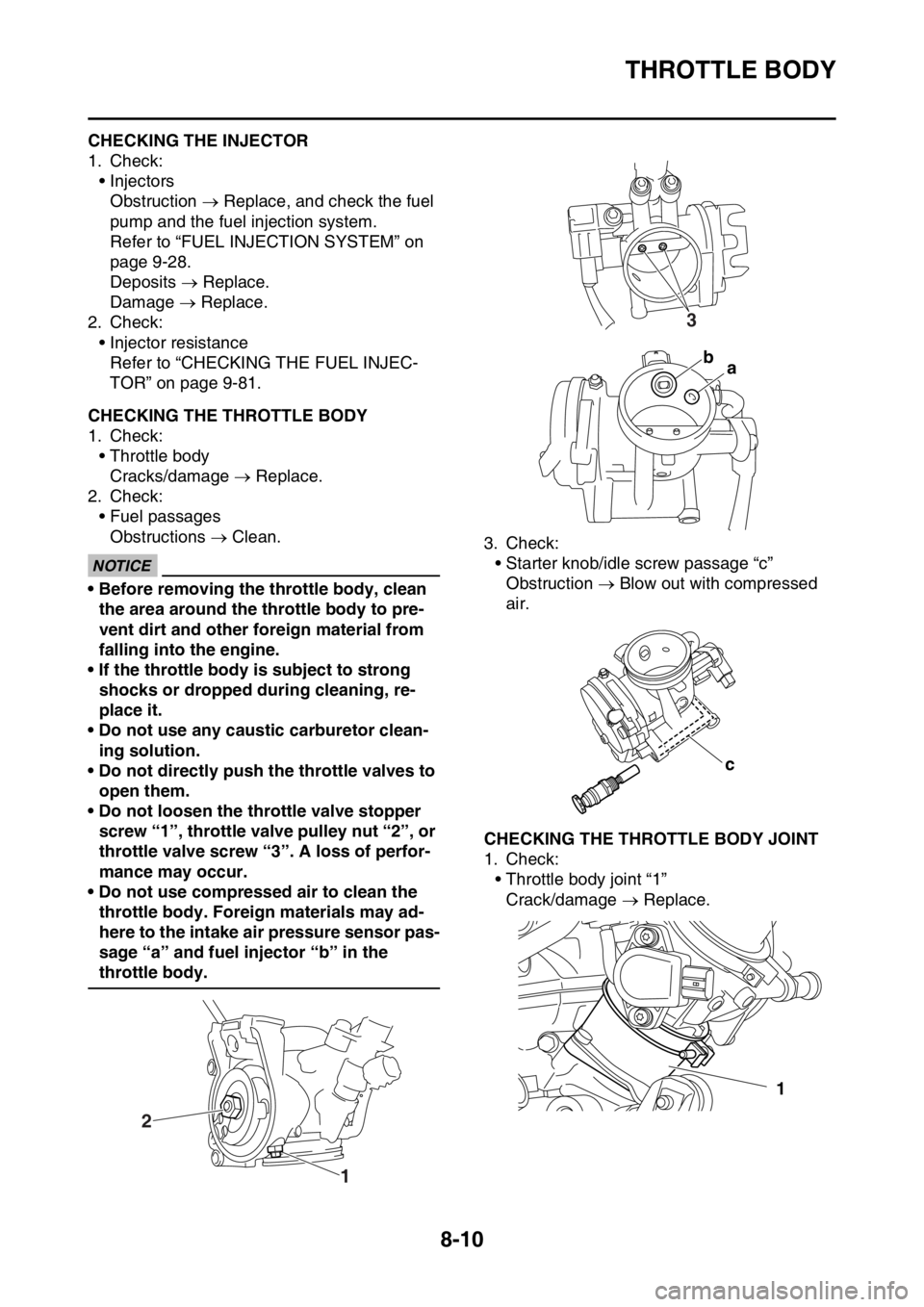
• Before removing the throttle body, clean
the area around the throttle body to pre-
vent dirt and other foreign material from
falling into the engine.
• If the throttle body is subject to strong
shocks or dropped during cleaning, re-
place it.
• Do not use any caustic carburetor clean-
ing solution.
• Do not directly push the throttle valves to
open them.
• Do not loosen the throttle valve stopper
screw “1”, throttle valve pulley nut “2”, or
throttle valve screw “3”. A loss of perfor-
mance may occur.
• Do not use compressed air to clean the
throttle body. Foreign materials may ad-
here to the intake air pressure sensor pas-
sage “a” and fuel injector “b” in the
throttle body.3. Check:
• Starter knob/idle screw passage “c”
Obstruction Blow out with compressed
air.
EAS2GB2356CHECKING THE THROTTLE BODY JOINT
1. Check:
• Throttle body joint “1”
Crack/damage Replace.
1 2
3
ba
c
1
Page 338 of 430

IGNITION SYSTEM
9-4
EAS2GB2361TROUBLESHOOTING
The ignition system fails to operate (no spark or intermittent spark).
TIP
Before troubleshooting, remove the following part (s):
1. Seat
2. Side cover (left/right)
3. Air scoop (left/right)
4. Fuel tank
5. Fuel tank
1. Check the fuse.
Refer to “CHECKING THE FUSES”
on page 9-68.NG
Replace the fuse(s).
OK
2. Check the battery.
Refer to “CHECKING AND
CHARGING THE BATTERY” on
page 9-69.NG
• Clean the battery terminals.
• Recharge or replace the battery.
OK
3. Check the spark plug.
Refer to “CHECKING THE FUSES”
on page 9-68.NG
Re-gap or replace the spark plug.
OK
4. Check the ignition spark gap.
Refer to “CHECKING THE IGNI-
TION SPARK GAP” on page 9-73.OK
The ignition system is normal.
NG
5. Check the ignition coil.
Refer to “CHECKING THE IGNI-
TION COIL” on page 9-74.NG
Replace the ignition coil.
OK
6. Check the crankshaft position sen-
sor.
Refer to “CHECKING THE CRANK-
SHAFT POSITION SENSOR” on
page 9-74.NG
Replace the stator assembly.
OK
7. Check the engine stop switch.
Refer to “CHECKING THE
SWITCHES” on page 9-64.NG
Replace the engine stop switch.
OK