YAMAHA WR 250F 2015 Owners Manual
WR 250F 2015
YAMAHA
YAMAHA
https://www.carmanualsonline.info/img/51/52293/w960_52293-0.png
YAMAHA WR 250F 2015 Owners Manual
Trending: fuel pressure, fuel, maintenance schedule, heating, oil additives, brake light, fuses
Page 391 of 430
FUEL PUMP SYSTEM
9-57
1. Joint connector
2. Joint connector
9. Battery
10.Frame ground
11.Starter relay
12.Main fuse
22.ECU (engine control unit)
26.Fuel pump
30.Joint connector
36.Engine stop switch
48.Frame ground
Page 392 of 430
FUEL PUMP SYSTEM
9-58
EAS2GB2382TROUBLESHOOTING
The fuel pump fails to operate.
TIP
Before troubleshooting, remove the following part(s):
1. Seat
2. Side cover (left/right)
3. Air scoop (left/right)
4. Fuel tank
1. Check the fuse.
Refer to “CHECKING THE FUSES”
on page 9-68.NG
Replace the fuse(s).
OK
2. Check the battery.
Refer to “CHECKING AND
CHARGING THE BATTERY” on
page 9-69.NG
• Clean the battery terminals.
• Recharge or replace the battery.
OK
3. Check the engine stop switch.
Refer to “CHECKING THE
SWITCHES” on page 9-64.NG
Replace the engine stop switch.
OK
4. Check fuel pressure.
Refer to “CHECKING THE FUEL
PRESSURE” on page 8-5.NG
Replace the fuel pump.
OK
5. Check the fuel pump system wire
harness connections.
Refer to “CIRCUIT DIAGRAM” on
page 9-56.NG
Properly connect or repair the fuel pump
system’s wiring.
OK
Replace the ECU.
Page 393 of 430
FUEL PUMP SYSTEM
9-59
EAS2GB2383
Page 394 of 430
ELECTRICAL COMPONENTS
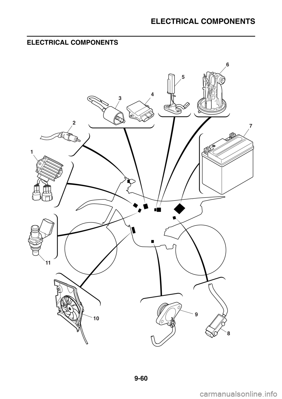
9-60 ELECTRICAL COMPONENTS
EAS2GB2384
910
11
1
3
2
456
7
8
Page 395 of 430
ELECTRICAL COMPONENTS
9-61
1. Rectifier/regulator
2. Clutch switch
3. Ignition coil
4. ECU (engine control unit)
5. Fuel sender
6. Fuel pump
7. Battery
8. Resistor
9. Neutral switch
10.Radiator fan motor
11.Injector
Page 396 of 430
ELECTRICAL COMPONENTS
9-62
12
1110
2
3
1
6
7
4
5
8
9
Page 397 of 430
ELECTRICAL COMPONENTS
9-63
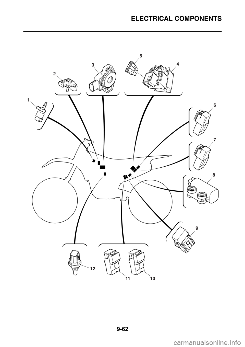
1. Intake air temperature sensor
2. Intake air pressure sensor
3. Throttle position sensor
4. Starter relay
5. Main fuse
6. Headlight relay
7. Starting circuit cut-off relay
8. Lean angle sensor
9. Radiator fan motor fuse
10.Radiator fan motor relay
11.Main relay
12.Coolant temperature sensor
Page 398 of 430
ELECTRICAL COMPONENTS
9-64
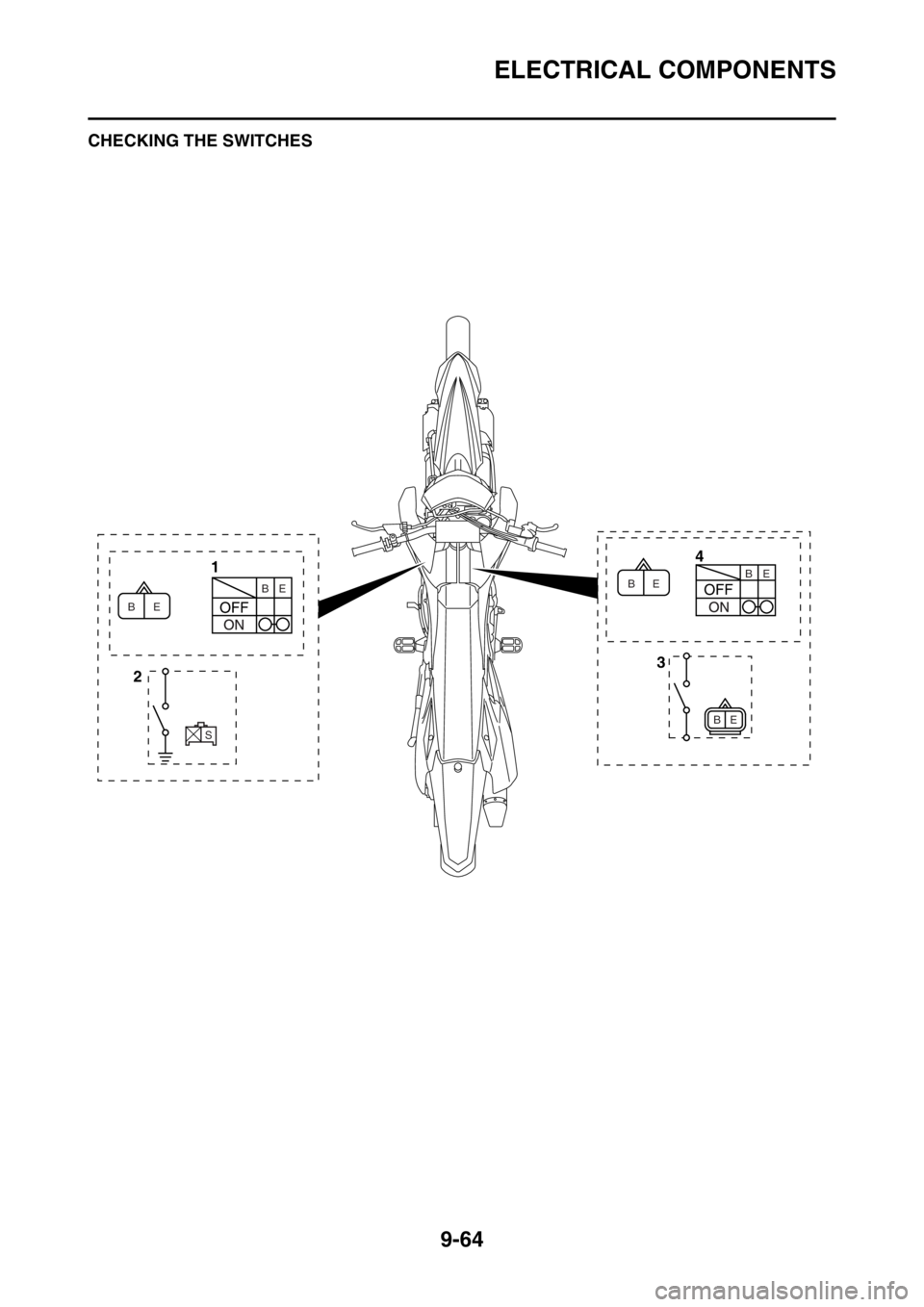
EAS2GB2385CHECKING THE SWITCHES
4
1
3
2
E B
S
E B
E BE
E BB
Page 399 of 430
ELECTRICAL COMPONENTS
9-65
1. Engine stop switch
2. Neutral switch
3. Clutch switch
4. Start switch
Page 400 of 430

ELECTRICAL COMPONENTS
9-66
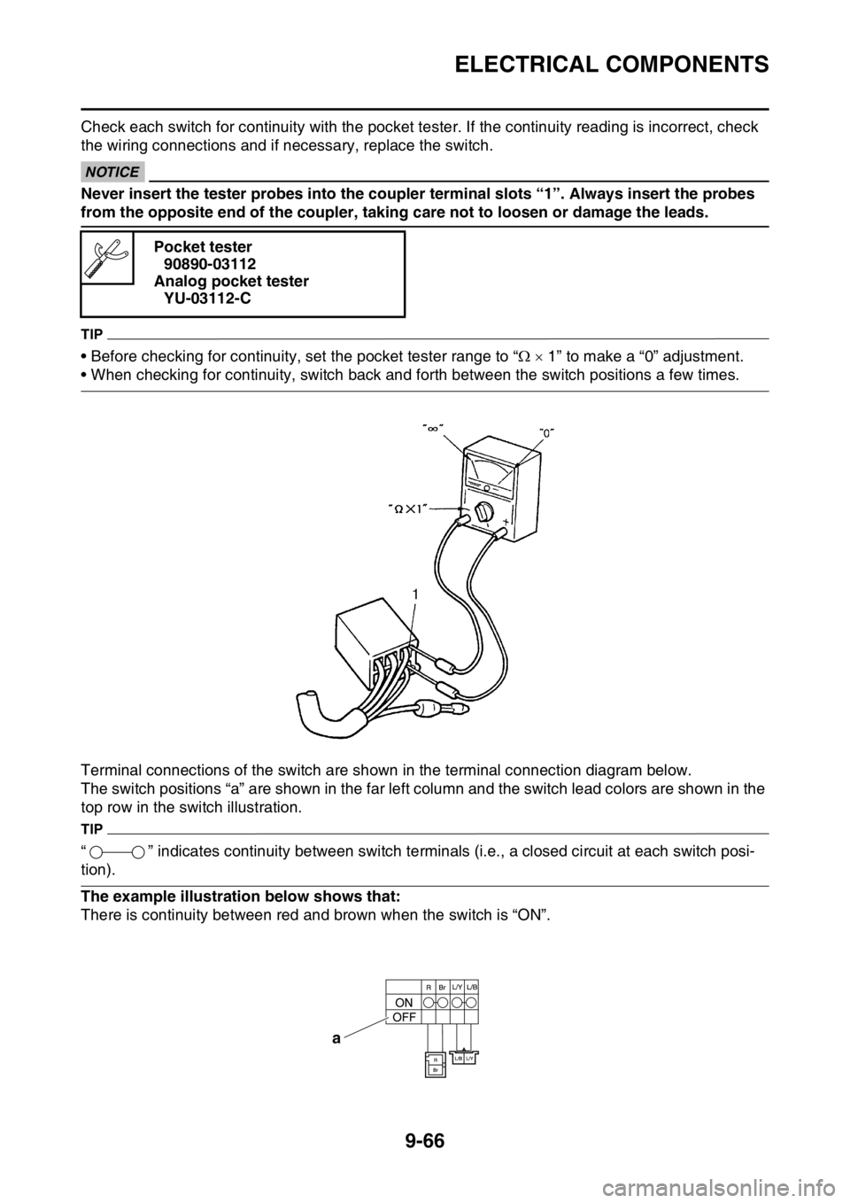
Check each switch for continuity with the pocket tester. If the continuity reading is incorrect, check
the wiring connections and if necessary, replace the switch.
ECA
NOTICE
Never insert the tester probes into the coupler terminal slots “1”. Always insert the probes
from the opposite end of the coupler, taking care not to loosen or damage the leads.
TIP
• Before checking for continuity, set the pocket tester range to “ 1” to make a “0” adjustment.
• When checking for continuity, switch back and forth between the switch positions a few times.
Terminal connections of the switch are shown in the terminal connection diagram below.
The switch positions “a” are shown in the far left column and the switch lead colors are shown in the
top row in the switch illustration.
TIP
“ ” indicates continuity between switch terminals (i.e., a closed circuit at each switch posi-
tion).
The example illustration below shows that:
There is continuity between red and brown when the switch is “ON”.Pocket tester
90890-03112
Analog pocket tester
YU-03112-C
a
Trending: maintenance schedule, fuses, climate control, drain bolt, parking brake, lock, set clock


