sensor YAMAHA WR 250F 2015 Workshop Manual
[x] Cancel search | Manufacturer: YAMAHA, Model Year: 2015, Model line: WR 250F, Model: YAMAHA WR 250F 2015Pages: 430, PDF Size: 14.14 MB
Page 377 of 430

FUEL INJECTION SYSTEM
9-43
TIP
• Make sure that the engine is completely cool before checking the intake air temperature sensor.
• Before troubleshooting, disconnect the starter motor lead from the starter relay. 5 Defective coolant tempera-
ture sensor.Execute the diagnostic mode.
(Code No. 06)
When engine is cold:
Displayed temperature is
close to the ambient temper-
ature.
The displayed temperature is
not close to the ambient tem-
perature. Check the cool-
ant temperature sensor.
Replace if defective.
Refer to “CHECKING THE
COOLANT TEMPERATURE
SENSOR” on page 9-78.Push the start switch.
Fault code number is not dis-
played Service is finished.
Fault code number is dis-
played Go to item 6.
6 Malfunction in ECU. Replace the ECU.
Fault code No. 22
Item Intake air temperature sensor: open or short circuit detected.
Fail-safe systemAble to start engine
Able to drive vehicle
Diagnostic code No.05
Diagnostic tool displayDisplays the intake air temperature.
ProcedureCompare the actually measured intake air temperature with the
Yamaha diagnostic tool display value.
ItemProbable cause of malfunc-
tion and checkMaintenance jobConfirmation of service
completion
1 Connection of intake air tem-
perature sensor coupler.
Check the locking condition
of the coupler.
Disconnect the coupler and
check the pins (bent or bro-
ken terminals and locking
condition of the pins).Improperly connected
Connect the coupler securely
or repair/replace the wire har-
ness.Push the start switch.
Fault code number is not dis-
played Service is finished.
Fault code number is dis-
played Go to item 2.
2 Connection of wire harness
ECU coupler.
Check the locking condition
of the coupler.
Disconnect the coupler and
check the pins (bent or bro-
ken terminals and locking
condition of the pins).Improperly connected
Connect the coupler securely
or repair/replace the wire har-
ness.Push the start switch.
Fault code number is not dis-
played Service is finished.
Fault code number is dis-
played Go to item 3. Fault code No. 21
Item Coolant temperature sensor: open or short circuit detected.
Page 378 of 430

FUEL INJECTION SYSTEM
9-44
TIP
Before troubleshooting, disconnect the starter motor lead from the starter relay. 3 Wire harness continuity. Open or short circuit Re-
place the wire harness.
Between intake air tempera-
ture sensor coupler and ECU
coupler.
black/blue–black/blue
brown/white–brown/whitePush the start switch.
Fault code number is not dis-
played Service is finished.
Fault code number is dis-
played Go to item 4.
4 Installed condition of intake
air temperature sensor.
Check for looseness or
pinching.Improperly installed sensor
Reinstall or replace the
sensor.Push the start switch.
Fault code number is not dis-
played Service is finished.
Fault code number is dis-
played Go to item 5.
5 Defective intake air tempera-
ture sensor.Execute the diagnostic mode.
(Code No. 05)
When engine is cold:
Displayed temperature is
close to the ambient temper-
ature.
The displayed temperature is
not close to the ambient tem-
perature. Check the intake
air temperature sensor.
Replace if defective.
Refer to “CHECKING THE
INTAKE AIR TEMPERA-
TURE SENSOR” on page 9-
80.Push the start switch.
Fault code number is not dis-
played Service is finished.
Fault code number is dis-
played Go to item 6.
6 Malfunction in ECU. Replace the ECU.
Fault code No. 30
Item Latch up detected.
Fail-safe systemUnable to start engine
Unable to drive vehicle
Diagnostic code No.08
Diagnostic tool displayLean angle sensor output voltage
• 0.4–1.4 (upright)
• 3.7–4.4 (overturned)
ProcedureRemove the lean angle sensor and incline it more than 45 degrees.
ItemProbable cause of malfunc-
tion and checkMaintenance jobConfirmation of service
completion
1 The vehicle has overturned. Raise the vehicle upright. Push the start switch.
Fault code number is not dis-
played Service is finished.
Fault code number is dis-
played Go to item 2. Fault code No. 22
Item Intake air temperature sensor: open or short circuit detected.
Page 379 of 430

FUEL INJECTION SYSTEM
9-45
2 Installed condition of lean an-
gle sensor.Check the installed direction
and condition of the sensor.Push the start switch.
Fault code number is not dis-
played Service is finished.
Fault code number is dis-
played Go to item 3.
3 Defective lean angle sensor. Execute the diagnostic mode.
(Code No. 08)
Replace if defective.
Refer to “CHECKING THE
LEAN ANGLE SENSOR” on
page 9-75.Push the start switch.
Fault code number is not dis-
played Service is finished.
Fault code number is dis-
played Go to item 4.
4 Malfunction in ECU. Replace the ECU.
Fault code No. 33
ItemIgnition coil: open or short circuit detected in the primary lead
of the ignition coil.
Fail-safe systemUnable to start engine
Unable to drive vehicle
Diagnostic code No.30
ActuationActuates the ignition coil five times at one-second intervals.
The engine trouble warning light and the “WARNING” on the
Yamaha diagnostic tool screen come on each time the ignition coil
is actuated.
ProcedureCheck that a spark is generated five times.
• Connect an ignition checker.
ItemProbable cause of malfunc-
tion and checkMaintenance jobConfirmation of service
completion
1 Connection of ignition coil
coupler.
Check the locking condition
of the coupler.
Disconnect the coupler and
check the pins (bent or bro-
ken terminals and locking
condition of the pins).Improperly connected
Connect the coupler securely
or repair/replace the wire har-
ness.Start the engine and let it idle
for approximately 5 seconds.
Fault code number is not dis-
played Service is finished.
Fault code number is dis-
played Go to item 2.
2 Connection of wire harness
ECU coupler.
Check the locking condition
of the coupler.
Disconnect the coupler and
check the pins (bent or bro-
ken terminals and locking
condition of the pins).Improperly connected
Connect the coupler securely
or repair/replace the wire har-
ness.Start the engine and let it idle
for approximately 5 seconds.
Fault code number is not dis-
played Service is finished.
Fault code number is dis-
played Go to item 3. Fault code No. 30
Item Latch up detected.
Page 380 of 430

FUEL INJECTION SYSTEM
9-46
3 Connection of sub wire har-
ness coupler.Check the lock-
ing condition of the
coupler.Disconnect the cou-
pler and check the pins (bent
or broken terminals and lock-
ing condition of the pins).Improperly connected
Connect the coupler secure-
lyor repair/replace the sub
wire harness.Start the engine and let it idle
for approximately 5 seconds.
Fault code number is not dis-
played Service is finished.
Fault code number is dis-
played Go to item 4.
4 Wire harness continuity. Open or short circuit Re-
place the wire harness.
Between ignition coil coupler
and ECU coupler.
orange–orangeStart the engine and let it idle
for approximately 5 seconds.
Fault code number is not dis-
played Service is finished.
Fault code number is dis-
played Go to item 5.
5 Installed condition of ignition
coil.
Check for looseness or
pinching.Improperly installed sensor
Reinstall or replace the
sensor.Start the engine and let it idle
for approximately 5 seconds.
Fault code number is not dis-
played Service is finished.
Fault code number is dis-
played Go to item 6.
6 Defective ignition coil. (test
the primary coils for continu-
ity)Check the ignition coil.
Replace if defective.
Refer to “CHECKING THE
IGNITION COIL” on page 9-
74.Start the engine and let it idle
for approximately 5 seconds.
Fault code number is not dis-
played Service is finished.
Fault code number is dis-
played Go to item 7.
7 Malfunction in ECU. Execute the diagnostic mode
(diagnostic code No. 30).
No spark Replace the
ECU. Fault code No. 33
ItemIgnition coil: open or short circuit detected in the primary lead
of the ignition coil.
Page 382 of 430

FUEL INJECTION SYSTEM
9-48
TIP
Before troubleshooting, disconnect the starter motor lead from the starter relay.
Fault code No. 41
Item Lean angle sensor: open or short circuit detected.
Fail-safe systemUnable to start engine
Able to drive vehicle
Diagnostic code No.08
Diagnostic tool displayLean angle sensor output voltage
• 0.4–1.4 (upright)
• 3.7–4.4 (overturned)
ProcedureRemove the lean angle sensor and incline it more than 45 degrees.
ItemProbable cause of malfunc-
tion and checkMaintenance jobConfirmation of service
completion
1 Connection of lean angle
sensor coupler.
Check the locking condition
of the coupler.
Disconnect the coupler and
check the pins (bent or bro-
ken terminals and locking
condition of the pins).Improperly connected
Connect the coupler securely
or repair/replace the wire har-
ness.Push the start switch.
Fault code number is not dis-
played Service is finished.
Fault code number is dis-
played Go to item 2.
2 Connection of wire harness
ECU coupler.
Check the locking condition
of the coupler.
Disconnect the coupler and
check the pins (bent or bro-
ken terminals and locking
condition of the pins).Improperly connected
Connect the coupler securely
or repair/replace the wire har-
ness.Push the start switch.
Fault code number is not dis-
played Service is finished.
Fault code number is dis-
played Go to item 3.
3 Wire harness continuity. Open or short circuit Re-
place the wire harness.
Between lean angle sensor
coupler and ECU coupler.
blue–blue
yellow/green–yellow/green
black/blue–black/bluePush the start switch.
Fault code number is not dis-
played Service is finished.
Fault code number is dis-
played Go to item 4.
4 Defective lean angle sensor. Execute the diagnostic mode.
(Code No. 08)
Replace if defective.
Refer to “CHECKING THE
LEAN ANGLE SENSOR” on
page 9-75.Push the start switch.
Fault code number is not dis-
played Service is finished.
Fault code number is dis-
played Go to item 5.
5 Malfunction in ECU. Replace the ECU.
Page 397 of 430

ELECTRICAL COMPONENTS
9-63
1. Intake air temperature sensor
2. Intake air pressure sensor
3. Throttle position sensor
4. Starter relay
5. Main fuse
6. Headlight relay
7. Starting circuit cut-off relay
8. Lean angle sensor
9. Radiator fan motor fuse
10.Radiator fan motor relay
11.Main relay
12.Coolant temperature sensor
Page 408 of 430

ELECTRICAL COMPONENTS
9-74
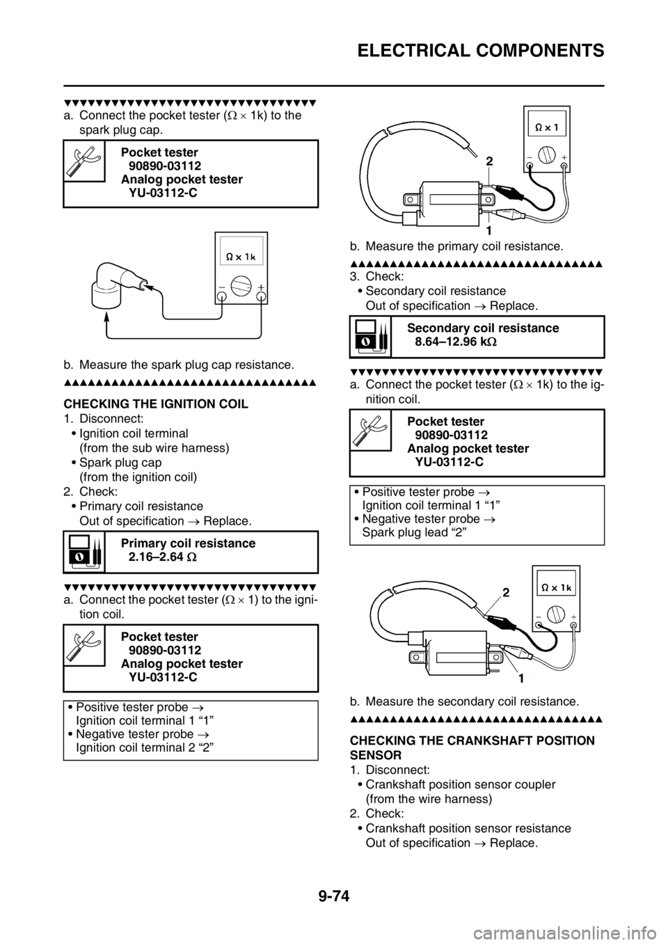
▼▼▼▼▼▼▼▼▼▼▼▼▼▼▼▼▼▼▼▼▼▼▼▼▼▼▼▼▼▼▼▼
a. Connect the pocket tester ( 1k) to the
spark plug cap.
b. Measure the spark plug cap resistance.
▲▲▲▲▲▲▲▲▲▲▲▲▲▲▲▲▲▲▲▲▲▲▲▲▲▲▲▲▲▲▲▲
EAS2GB2392CHECKING THE IGNITION COIL
1. Disconnect:
• Ignition coil terminal
(from the sub wire harness)
• Spark plug cap
(from the ignition coil)
2. Check:
• Primary coil resistance
Out of specification Replace.
▼▼▼▼▼▼▼▼▼▼▼▼▼▼▼▼▼▼▼▼▼▼▼▼▼▼▼▼▼▼▼▼
a. Connect the pocket tester ( 1) to the igni-
tion coil.b. Measure the primary coil resistance.
▲▲▲▲▲▲▲▲▲▲▲▲▲▲▲▲▲▲▲▲▲▲▲▲▲▲▲▲▲▲▲▲
3. Check:
• Secondary coil resistance
Out of specification Replace.
▼▼▼▼▼▼▼▼▼▼▼▼▼▼▼▼▼▼▼▼▼▼▼▼▼▼▼▼▼▼▼▼
a. Connect the pocket tester ( 1k) to the ig-
nition coil.
b. Measure the secondary coil resistance.
▲▲▲▲▲▲▲▲▲▲▲▲▲▲▲▲▲▲▲▲▲▲▲▲▲▲▲▲▲▲▲▲
EAS2GB2393CHECKING THE CRANKSHAFT POSITION
SENSOR
1. Disconnect:
• Crankshaft position sensor coupler
(from the wire harness)
2. Check:
• Crankshaft position sensor resistance
Out of specification Replace. Pocket tester
90890-03112
Analog pocket tester
YU-03112-C
Primary coil resistance
2.16–2.64
Pocket tester
90890-03112
Analog pocket tester
YU-03112-C
• Positive tester probe
Ignition coil terminal 1 “1”
• Negative tester probe
Ignition coil terminal 2 “2”
Secondary coil resistance
8.64–12.96 k
Pocket tester
90890-03112
Analog pocket tester
YU-03112-C
• Positive tester probe
Ignition coil terminal 1 “1”
• Negative tester probe
Spark plug lead “2”
Page 409 of 430

ELECTRICAL COMPONENTS
9-75
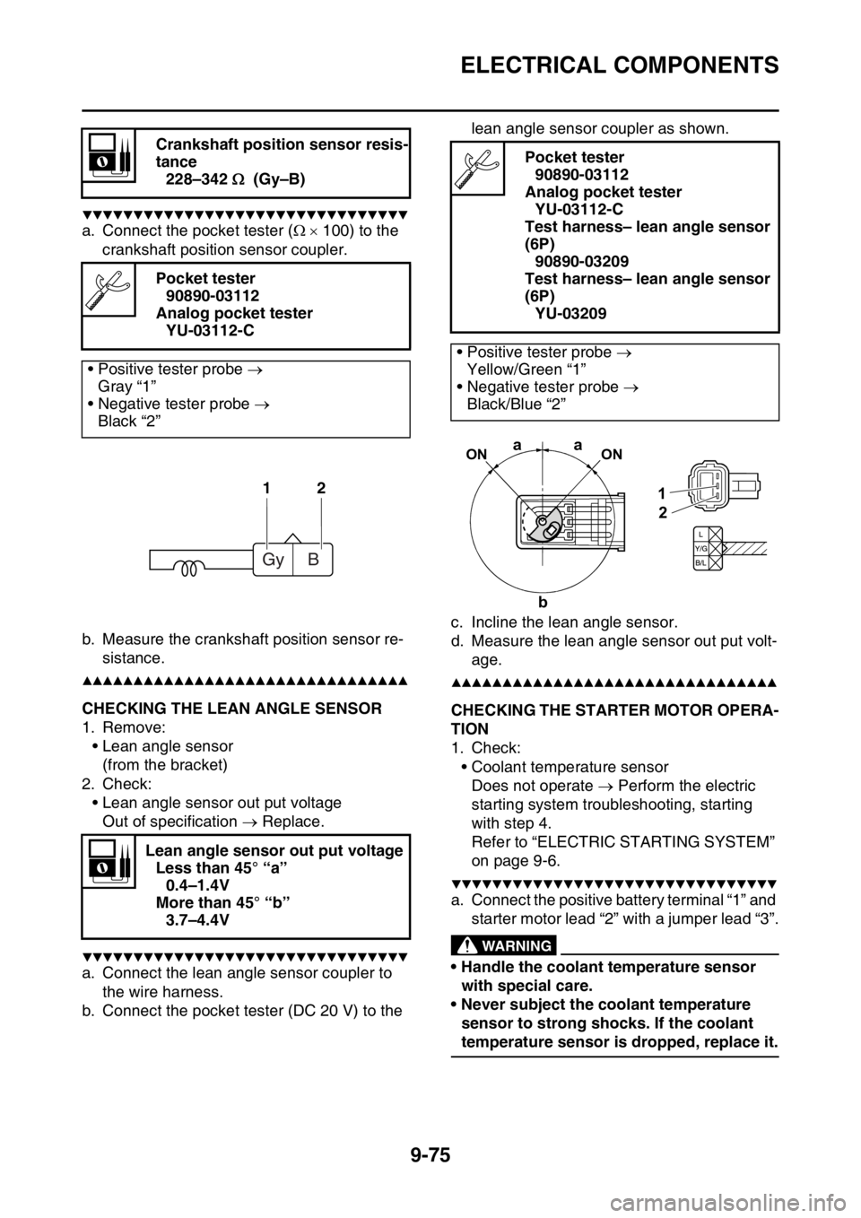
▼▼▼▼▼▼▼▼▼▼▼▼▼▼▼▼▼▼▼▼▼▼▼▼▼▼▼▼▼▼▼▼
a. Connect the pocket tester ( 100) to the
crankshaft position sensor coupler.
b. Measure the crankshaft position sensor re-
sistance.
▲▲▲▲▲▲▲▲▲▲▲▲▲▲▲▲▲▲▲▲▲▲▲▲▲▲▲▲▲▲▲▲
EAS2GB2394CHECKING THE LEAN ANGLE SENSOR
1. Remove:
• Lean angle sensor
(from the bracket)
2. Check:
• Lean angle sensor out put voltage
Out of specification Replace.
▼▼▼▼▼▼▼▼▼▼▼▼▼▼▼▼▼▼▼▼▼▼▼▼▼▼▼▼▼▼▼▼
a. Connect the lean angle sensor coupler to
the wire harness.
b. Connect the pocket tester (DC 20 V) to the lean angle sensor coupler as shown.
c. Incline the lean angle sensor.
d. Measure the lean angle sensor out put volt-
age.
▲▲▲▲▲▲▲▲▲▲▲▲▲▲▲▲▲▲▲▲▲▲▲▲▲▲▲▲▲▲▲▲
EAS2GB2395CHECKING THE STARTER MOTOR OPERA-
TION
1. Check:
• Coolant temperature sensor
Does not operate Perform the electric
starting system troubleshooting, starting
with step 4.
Refer to “ELECTRIC STARTING SYSTEM”
on page 9-6.
▼▼▼▼▼▼▼▼▼▼▼▼▼▼▼▼▼▼▼▼▼▼▼▼▼▼▼▼▼▼▼▼
a. Connect the positive battery terminal “1” and
starter motor lead “2” with a jumper lead “3”.
EWA
WARNING
• Handle the coolant temperature sensor
with special care.
• Never subject the coolant temperature
sensor to strong shocks. If the coolant
temperature sensor is dropped, replace it. Crankshaft position sensor resis-
tance
228–342 (Gy–B)
Pocket tester
90890-03112
Analog pocket tester
YU-03112-C
• Positive tester probe
Gray “1”
• Negative tester probe
Black “2”
Lean angle sensor out put voltage
Less than 45° “a”
0.4–1.4V
More than 45° “b”
3.7–4.4V
12
Gy B
Pocket tester
90890-03112
Analog pocket tester
YU-03112-C
Test harness– lean angle sensor
(6P)
90890-03209
Test harness– lean angle sensor
(6P)
YU-03209
• Positive tester probe
Yellow/Green “1”
• Negative tester probe
Black/Blue “2”
2 1
aa
bON ON
Page 411 of 430

ELECTRICAL COMPONENTS
9-77
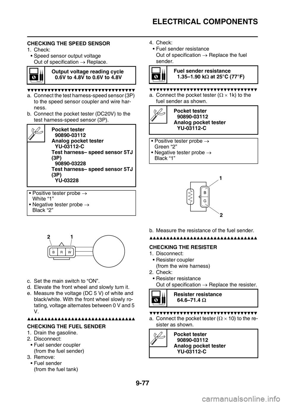
EAS2GB2397CHECKING THE SPEED SENSOR
1. Check:
• Speed sensor output voltage
Out of specification Replace.
▼▼▼▼▼▼▼▼▼▼▼▼▼▼▼▼▼▼▼▼▼▼▼▼▼▼▼▼▼▼▼▼
a. Connect the test harness-speed sensor (3P)
to the speed sensor coupler and wire har-
ness.
b. Connect the pocket tester (DC20V) to the
test harness-speed sensor (3P).
c. Set the main switch to “ON”.
d. Elevate the front wheel and slowly turn it.
e. Measure the voltage (DC 5 V) of white and
black/white. With the front wheel slowly ro-
tating, voltage alternates between 0 V and 5
V.
▲▲▲▲▲▲▲▲▲▲▲▲▲▲▲▲▲▲▲▲▲▲▲▲▲▲▲▲▲▲▲▲EAS2GB2398CHECKING THE FUEL SENDER
1. Drain the gasoline.
2. Disconnect:
• Fuel sender coupler
(from the fuel sender)
3. Remove:
• Fuel sender
(from the fuel tank)4. Check:
• Fuel sender resistance
Out of specification Replace the fuel
sender.
▼▼▼▼▼▼▼▼▼▼▼▼▼▼▼▼▼▼▼▼▼▼▼▼▼▼▼▼▼▼▼▼
a. Connect the pocket tester ( 1k) to the
fuel sender as shown.
b. Measure the resistance of the fuel sender.
▲▲▲▲▲▲▲▲▲▲▲▲▲▲▲▲▲▲▲▲▲▲▲▲▲▲▲▲▲▲▲▲
EAS2GB2399CHECKING THE RESISTER
1. Disconnect:
• Resister coupler
(from the wire harness)
2. Check:
• Resister resistance
Out of specification Replace the resister.
▼▼▼▼▼▼▼▼▼▼▼▼▼▼▼▼▼▼▼▼▼▼▼▼▼▼▼▼▼▼▼▼
a. Connect the pocket tester ( 10) to the re-
sister as shown. Output voltage reading cycle
0.6V to 4.8V to 0.6V to 4.8V
Pocket tester
90890-03112
Analog pocket tester
YU-03112-C
Test harness– speed sensor 5TJ
(3P)
90890-03228
Test harness– speed sensor 5TJ
(3P)
YU-03228
• Positive tester probe
White “1”
• Negative tester probe
Black “2”
BRW
21
Fuel sender resistance
1.35–1.90 k at 25°C (77°F)
Pocket tester
90890-03112
Analog pocket tester
YU-03112-C
• Positive tester probe
Green “2”
• Negative tester probe
Black “1”
Resister resistance
64.6–71.4
Pocket tester
90890-03112
Analog pocket tester
YU-03112-C
1
2
Page 412 of 430

ELECTRICAL COMPONENTS
9-78
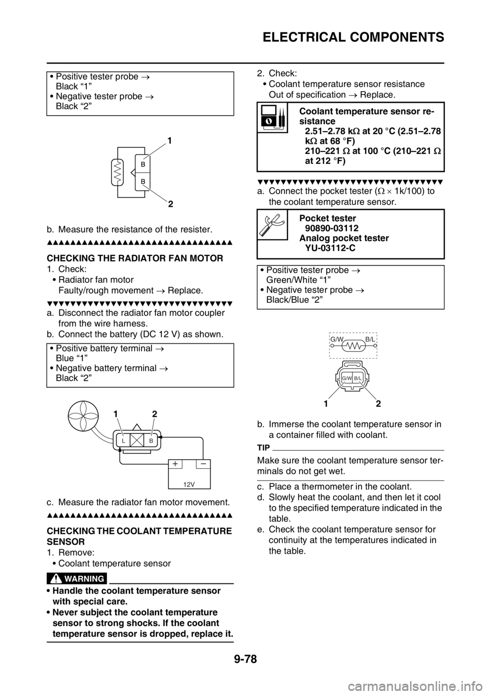
b. Measure the resistance of the resister.
▲▲▲▲▲▲▲▲▲▲▲▲▲▲▲▲▲▲▲▲▲▲▲▲▲▲▲▲▲▲▲▲
EAS2GB2400CHECKING THE RADIATOR FAN MOTOR
1. Check:
• Radiator fan motor
Faulty/rough movement Replace.
▼▼▼▼▼▼▼▼▼▼▼▼▼▼▼▼▼▼▼▼▼▼▼▼▼▼▼▼▼▼▼▼
a. Disconnect the radiator fan motor coupler
from the wire harness.
b. Connect the battery (DC 12 V) as shown.
c. Measure the radiator fan motor movement.
▲▲▲▲▲▲▲▲▲▲▲▲▲▲▲▲▲▲▲▲▲▲▲▲▲▲▲▲▲▲▲▲
EAS2GB2401CHECKING THE COOLANT TEMPERATURE
SENSOR
1. Remove:
• Coolant temperature sensor
EWA
WARNING
• Handle the coolant temperature sensor
with special care.
• Never subject the coolant temperature
sensor to strong shocks. If the coolant
temperature sensor is dropped, replace it.2. Check:
• Coolant temperature sensor resistance
Out of specification Replace.
▼▼▼▼▼▼▼▼▼▼▼▼▼▼▼▼▼▼▼▼▼▼▼▼▼▼▼▼▼▼▼▼
a. Connect the pocket tester ( 1k/100) to
the coolant temperature sensor.
b. Immerse the coolant temperature sensor in
a container filled with coolant.
TIP
Make sure the coolant temperature sensor ter-
minals do not get wet.
c. Place a thermometer in the coolant.
d. Slowly heat the coolant, and then let it cool
to the specified temperature indicated in the
table.
e. Check the coolant temperature sensor for
continuity at the temperatures indicated in
the table. • Positive tester probe
Black “1”
• Negative tester probe
Black “2”
• Positive battery terminal
Blue “1”
• Negative battery terminal
Black “2”
1
2
12
12V
LB
Coolant temperature sensor re-
sistance
2.51–2.78 k at 20 °C (2.51–2.78
k at 68 °F)
210–221 at 100 °C (210–221
at 212 °F)
Pocket tester
90890-03112
Analog pocket tester
YU-03112-C
• Positive tester probe
Green/White “1”
• Negative tester probe
Black/Blue “2”
12
G/W B/L
B/L G/W