sensor YAMAHA WR 250F 2015 Owner's Manual
[x] Cancel search | Manufacturer: YAMAHA, Model Year: 2015, Model line: WR 250F, Model: YAMAHA WR 250F 2015Pages: 430, PDF Size: 14.14 MB
Page 234 of 430
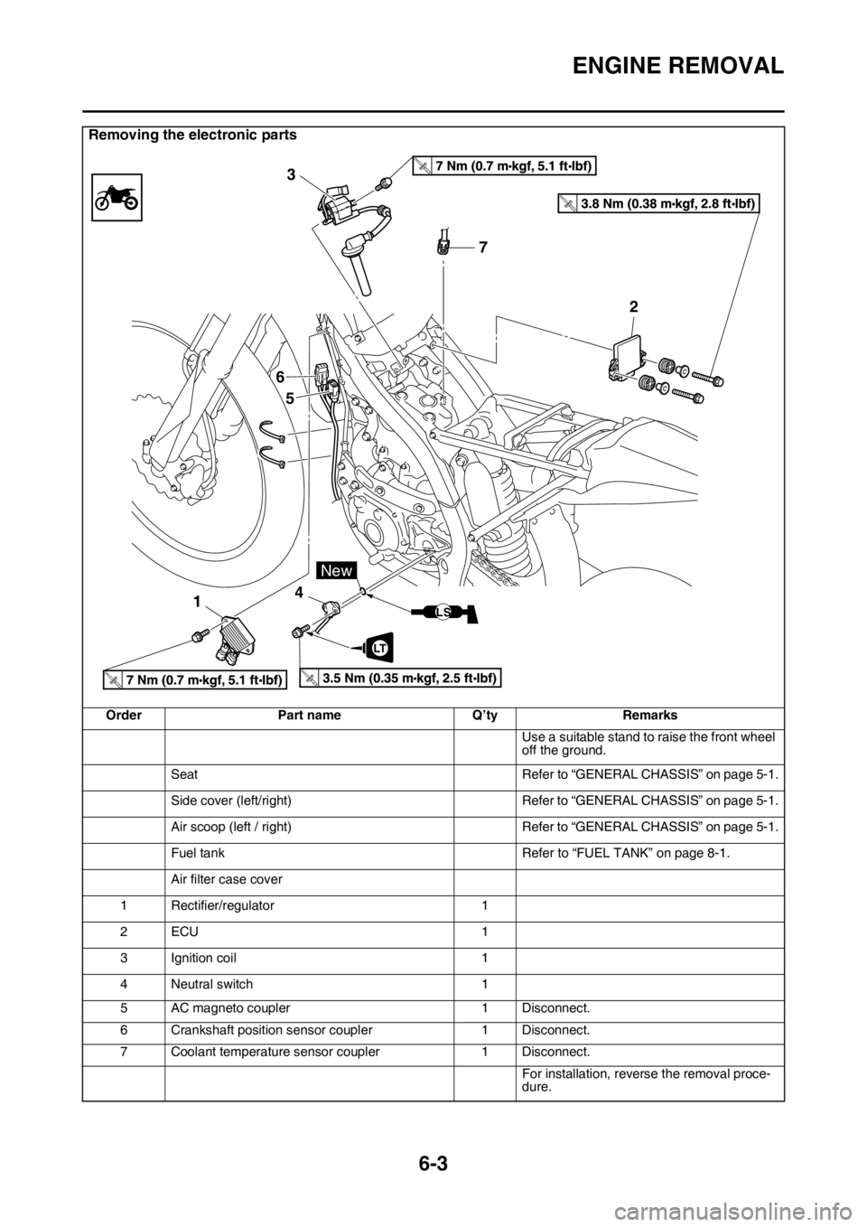
ENGINE REMOVAL
6-3
Removing the electronic parts
Order Part name Q’ty Remarks
Use a suitable stand to raise the front wheel
off the ground.
Seat Refer to “GENERAL CHASSIS” on page 5-1.
Side cover (left/right) Refer to “GENERAL CHASSIS” on page 5-1.
Air scoop (left / right) Refer to “GENERAL CHASSIS” on page 5-1.
Fuel tank Refer to “FUEL TANK” on page 8-1.
Air filter case cover
1 Rectifier/regulator 1
2ECU 1
3 Ignition coil 1
4 Neutral switch 1
5 AC magneto coupler 1 Disconnect.
6 Crankshaft position sensor coupler 1 Disconnect.
7 Coolant temperature sensor coupler 1 Disconnect.
For installation, reverse the removal proce-
dure.
T.R.
T.R.
T.R.T.R.
7 3
6
5
142
LT
New
LS
Page 249 of 430
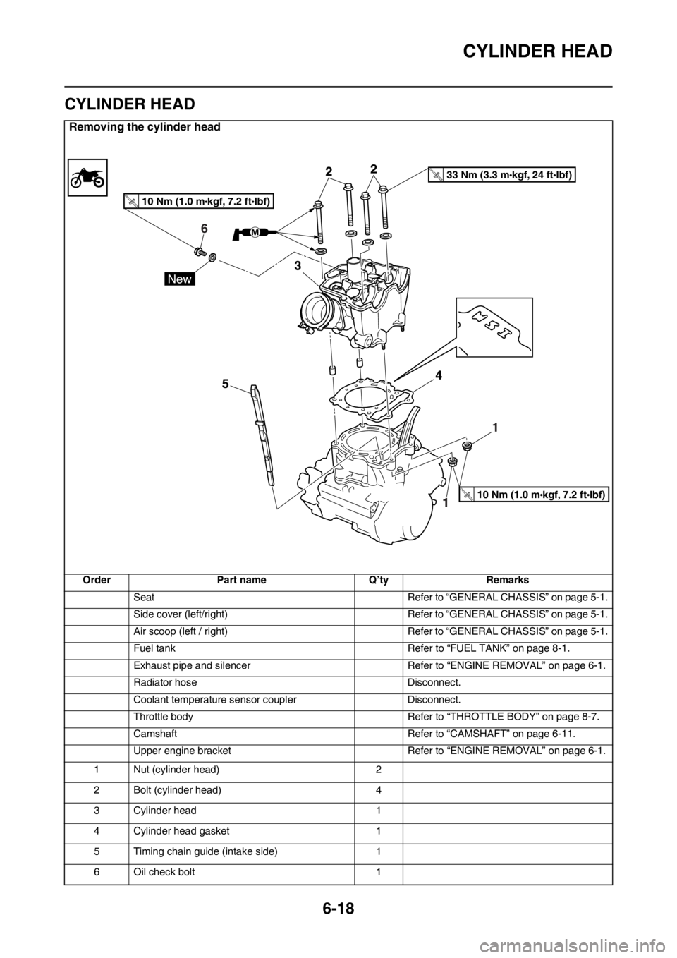
CYLINDER HEAD
6-18
EAS2GB2246
CYLINDER HEAD
Removing the cylinder head
Order Part name Q’ty Remarks
Seat Refer to “GENERAL CHASSIS” on page 5-1.
Side cover (left/right) Refer to “GENERAL CHASSIS” on page 5-1.
Air scoop (left / right) Refer to “GENERAL CHASSIS” on page 5-1.
Fuel tank Refer to “FUEL TANK” on page 8-1.
Exhaust pipe and silencer Refer to “ENGINE REMOVAL” on page 6-1.
Radiator hose Disconnect.
Coolant temperature sensor coupler Disconnect.
Throttle body Refer to “THROTTLE BODY” on page 8-7.
Camshaft Refer to “CAMSHAFT” on page 6-11.
Upper engine bracket Refer to “ENGINE REMOVAL” on page 6-1.
1 Nut (cylinder head) 2
2 Bolt (cylinder head) 4
3 Cylinder head 1
4 Cylinder head gasket 1
5 Timing chain guide (intake side) 1
6 Oil check bolt 1
6
10 Nm (1.0 m kgf, 7.2 ft Ibf)T.R.
33 Nm (3.3 m kgf, 24 ft Ibf)T.R.
10 Nm (1.0 m kgf, 7.2 ft Ibf)T.R.
Page 294 of 430
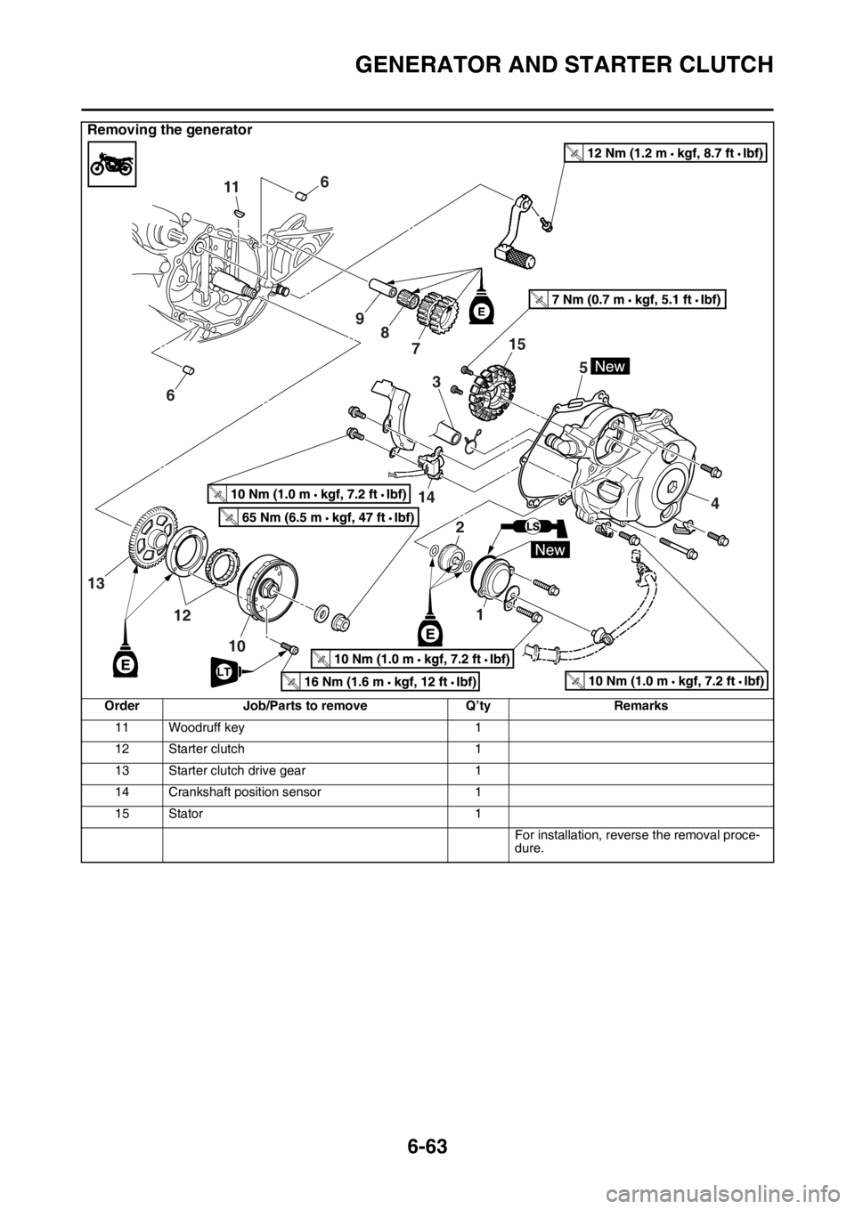
GENERATOR AND STARTER CLUTCH
6-63
11 Woodruff key 1
12 Starter clutch 1
13 Starter clutch drive gear 1
14 Crankshaft position sensor 1
15 Stator 1
For installation, reverse the removal proce-
dure.
Removing the generator
Order Job/Parts to remove Q’ty Remarks
T R..
T R..
6
611
9
8
7
2
3
1
14
4 5
12
10
13
T R..
T R..
T R..LTT R..
T R..
15
Page 296 of 430
GENERATOR AND STARTER CLUTCH
6-65
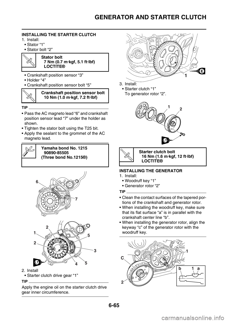
EAS2GB2310INSTALLING THE STARTER CLUTCH
1. Install:
• Stator “1”
• Stator bolt “2”
• Crankshaft position sensor “3”
• Holder “4”
• Crankshaft position sensor bolt “5”
TIP
• Pass the AC magneto lead “6” and crankshaft
position sensor lead “7” under the holder as
shown.
• Tighten the stator bolt using the T25 bit.
• Apply the sealant to the grommet of the AC
magneto lead.
2. Install
• Starter clutch drive gear “1”
TIP
Apply the engine oil on the starter clutch drive
gear inner circumference.3. Install:
• Starter clutch “1”
To generator rotor “2”.
EAS2GB2311INSTALLING THE GENERATOR
1. Install:
• Woodruff key “1”
• Generator rotor “2”
TIP
• Clean the contact surfaces of the tapered por-
tions of the crankshaft and generator rotor.
• When installing the woodruff key, make sure
that its flat surface “a” is in parallel with the
crankshaft center line “b”.
• When installing the generator rotor, align the
keyway “c” of the generator rotor with the
woodruff key. Stator bolt
7 Nm (0.7 m·kgf, 5.1 ft·lbf)
LOCTITE®
Crankshaft position sensor bolt
10 Nm (1.0 m·kgf, 7.2 ft·lbf)
Yamaha bond No. 1215
90890-85505
(Three bond No.1215®)
T R..
T R..
6
7
1
3
22
5
5
4LT
Starter clutch bolt
16 Nm (1.6 m·kgf, 12 ft·lbf)
LOCTITE®
21
LT
T R..
2 C1 1
1a b
Page 315 of 430
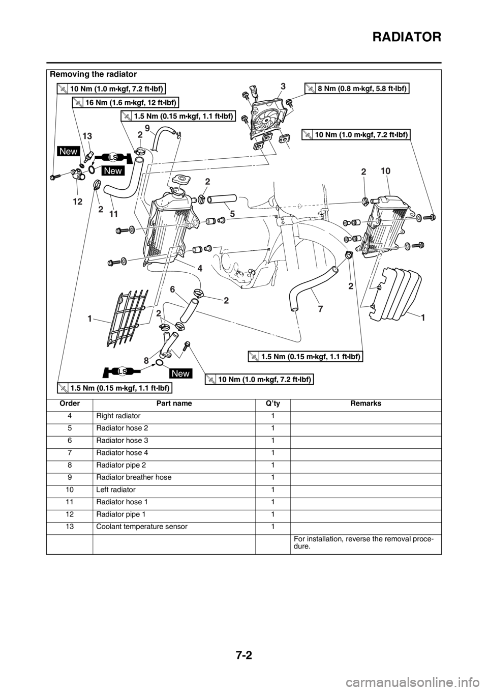
RADIATOR
7-2
4 Right radiator 1
5 Radiator hose 2 1
6 Radiator hose 3 1
7 Radiator hose 4 1
8 Radiator pipe 2 1
9 Radiator breather hose 1
10 Left radiator 1
11 Radiator hose 1 1
12 Radiator pipe 1 1
13 Coolant temperature sensor 1
For installation, reverse the removal proce-
dure.
Removing the radiator
Order Part name Q’ty Remarks
12
13
New
New
New
LS
LS
3
458 Nm (0.8 m kgf, 5.8 ft Ibf)T.R.
6
7
89
10
112
2
2
2 22 2
1
1
Page 321 of 430

8
FUEL SYSTEM
FUEL TANK...................................................................................................... 8-1
REMOVING THE FUEL TANK ................................................................... 8-3
REMOVING THE FUEL PUMP .................................................................. 8-3
CHECKING THE FUEL PUMP BODY........................................................ 8-3
INSTALLING THE FUEL PUMP ................................................................. 8-3
REMOVING THE FUEL SENDER.............................................................. 8-4
CHECKING THE FUEL SENDER .............................................................. 8-4
INSTALLING THE FUEL SENDER ............................................................ 8-4
INSTALLING THE FUEL TANK.................................................................. 8-4
CHECKING THE FUEL PRESSURE ......................................................... 8-5
CHECKING THE DAMPER ........................................................................ 8-5
CHECKING AND REPLACING THE PROTECTOR .................................. 8-6
THROTTLE BODY............................................................................................ 8-7
CHECKING THE INJECTOR ................................................................... 8-10
CHECKING THE THROTTLE BODY ....................................................... 8-10
CHECKING THE THROTTLE BODY JOINT ............................................ 8-10
ADJUSTING THE THROTTLE POSITION SENSOR............................... 8-11
Page 328 of 430
THROTTLE BODY
8-7
EAS2GB2353
THROTTLE BODY
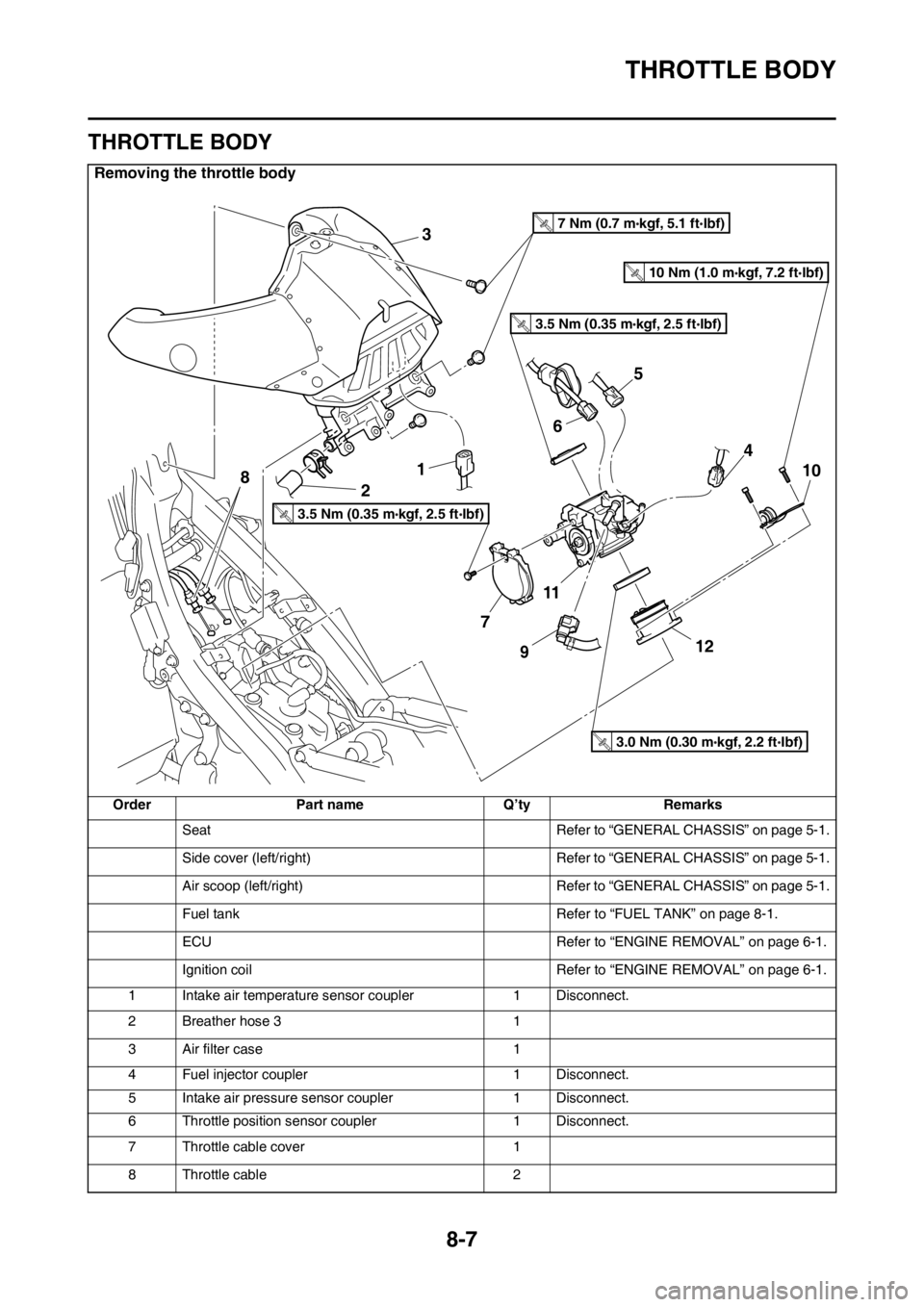
Removing the throttle body
Order Part name Q’ty Remarks
Seat Refer to “GENERAL CHASSIS” on page 5-1.
Side cover (left/right) Refer to “GENERAL CHASSIS” on page 5-1.
Air scoop (left/right) Refer to “GENERAL CHASSIS” on page 5-1.
Fuel tank Refer to “FUEL TANK” on page 8-1.
ECU Refer to “ENGINE REMOVAL” on page 6-1.
Ignition coil Refer to “ENGINE REMOVAL” on page 6-1.
1 Intake air temperature sensor coupler 1 Disconnect.
2 Breather hose 3 1
3 Air filter case 1
4 Fuel injector coupler 1 Disconnect.
5 Intake air pressure sensor coupler 1 Disconnect.
6 Throttle position sensor coupler 1 Disconnect.
7 Throttle cable cover 1
8 Throttle cable 2
3
1
2
7
11
12
10
9
4
8
6
5
3.5 Nm (0.35 m kgf, 2.5 ft Ibf)T.R.
3.5 Nm (0.35 m kgf, 2.5 ft Ibf)T.R.
7 Nm (0.7 m kgf, 5.1 ft Ibf)T.R.
3.0 Nm (0.30 m kgf, 2.2 ft Ibf)T.R.
10 Nm (1.0 m kgf, 7.2 ft Ibf)T.R.
Page 330 of 430
THROTTLE BODY
8-9
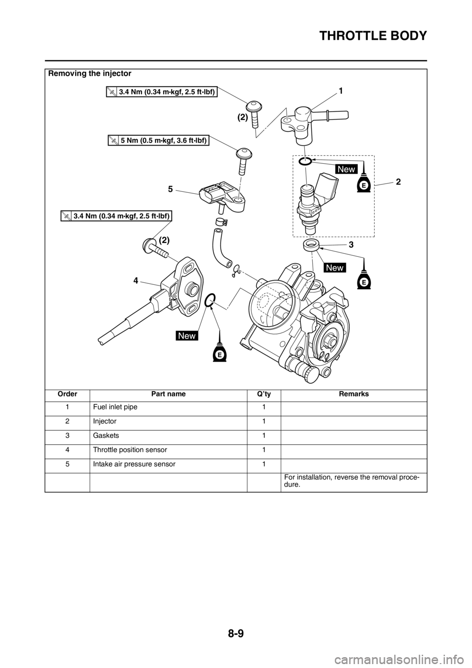
Removing the injector
Order Part name Q’ty Remarks
1 Fuel inlet pipe 1
2Injector 1
3 Gaskets 1
4 Throttle position sensor 1
5 Intake air pressure sensor 1
For installation, reverse the removal proce-
dure.
1
2 (2)
(2)5
43
T.R.3.4 Nm (0.34 mlbf) kgf, 2.5 ft
T.R.5 Nm (0.5 mlbf) kgf, 3.6 ft
T.R.3.4 Nm (0.34 mlbf) kgf, 2.5 ft
Page 331 of 430
THROTTLE BODY
8-10
EAS2GB2354CHECKING THE INJECTOR
1. Check:
• Injectors
Obstruction Replace, and check the fuel
pump and the fuel injection system.
Refer to “FUEL INJECTION SYSTEM” on
page 9-28.
Deposits Replace.
Damage Replace.
2. Check:
• Injector resistance
Refer to “CHECKING THE FUEL INJEC-
TOR” on page 9-81.
EAS2GB2355CHECKING THE THROTTLE BODY
1. Check:
• Throttle body
Cracks/damage Replace.
2. Check:
• Fuel passages
Obstructions Clean.
ECA
NOTICE
• Before removing the throttle body, clean
the area around the throttle body to pre-
vent dirt and other foreign material from
falling into the engine.
• If the throttle body is subject to strong
shocks or dropped during cleaning, re-
place it.
• Do not use any caustic carburetor clean-
ing solution.
• Do not directly push the throttle valves to
open them.
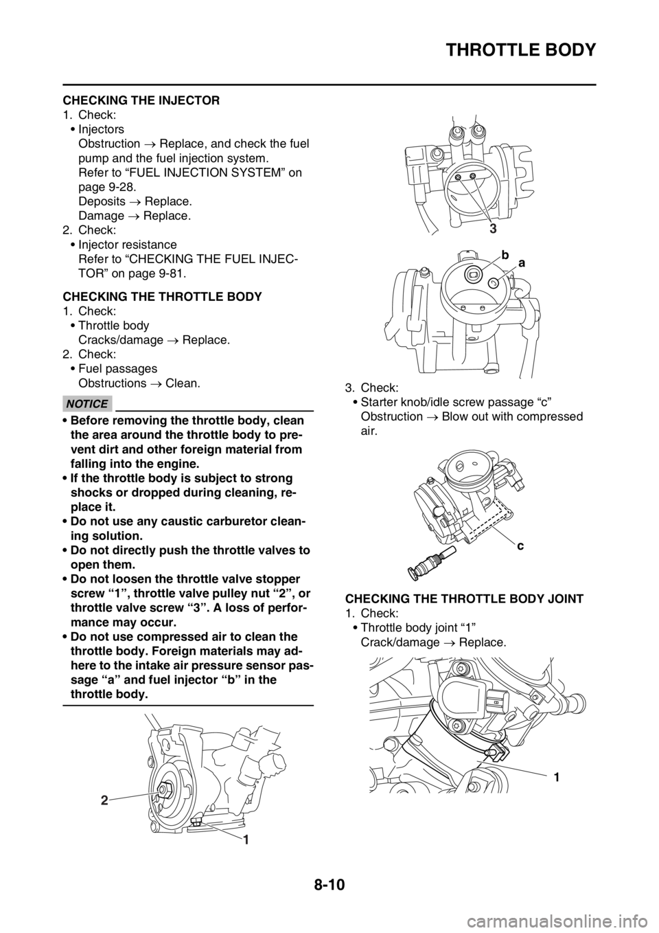
• Do not loosen the throttle valve stopper
screw “1”, throttle valve pulley nut “2”, or
throttle valve screw “3”. A loss of perfor-
mance may occur.
• Do not use compressed air to clean the
throttle body. Foreign materials may ad-
here to the intake air pressure sensor pas-
sage “a” and fuel injector “b” in the
throttle body.3. Check:
• Starter knob/idle screw passage “c”
Obstruction Blow out with compressed
air.
EAS2GB2356CHECKING THE THROTTLE BODY JOINT
1. Check:
• Throttle body joint “1”
Crack/damage Replace.
1 2
3
ba
c
1
Page 332 of 430
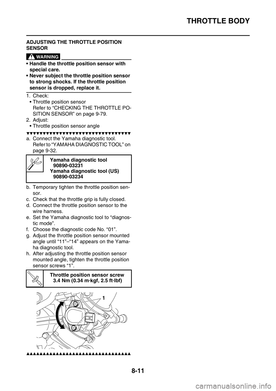
THROTTLE BODY
8-11
EAS2GB2357ADJUSTING THE THROTTLE POSITION
SENSOR
EWA
WARNING
• Handle the throttle position sensor with
special care.
• Never subject the throttle position sensor
to strong shocks. If the throttle position
sensor is dropped, replace it.
1. Check:
• Throttle position sensor
Refer to “CHECKING THE THROTTLE PO-
SITION SENSOR” on page 9-79.
2. Adjust:
• Throttle position sensor angle
▼▼▼▼▼▼▼▼▼▼▼▼▼▼▼▼▼▼▼▼▼▼▼▼▼▼▼▼▼▼▼▼
a. Connect the Yamaha diagnostic tool.
Refer to “YAMAHA DIAGNOSTIC TOOL” on
page 9-32.
b. Temporary tighten the throttle position sen-
sor.
c. Check that the throttle grip is fully closed.
d. Connect the throttle position sensor to the
wire harness.
e. Set the Yamaha diagnostic tool to “diagnos-
tic mode”.
f. Choose the diagnostic code No. “01”.
g. Adjust the throttle position sensor mounted
angle until “11”–“14” appears on the Yama-
ha diagnostic tool.
h. After adjusting the throttle position sensor
mounted angle, tighten the throttle position
sensor screws “1”.
▲▲▲▲▲▲▲▲▲▲▲▲▲▲▲▲▲▲▲▲▲▲▲▲▲▲▲▲▲▲▲▲
Yamaha diagnostic tool
90890-03231
Yamaha diagnostic tool (US)
90890-03234
Throttle position sensor screw
3.4 Nm (0.34 m·kgf, 2.5 ft·lbf)
T R..
1