YAMAHA WR 400F 2000 Notices Demploi (in French)
Manufacturer: YAMAHA, Model Year: 2000, Model line: WR 400F, Model: YAMAHA WR 400F 2000Pages: 654, PDF Size: 60.12 MB
Page 141 of 654
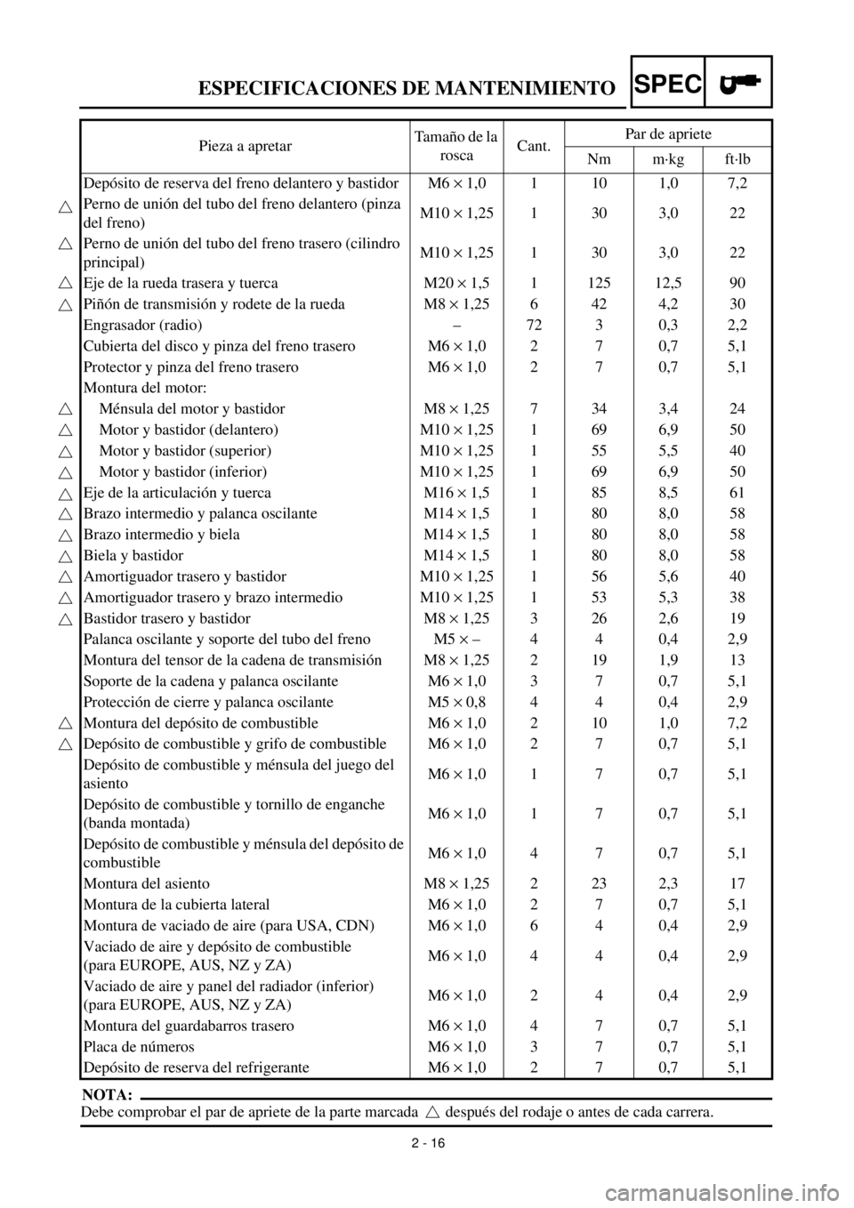
2 - 16
SPECESPECIFICACIONES DE MANTENIMIENTO
NOTA:
Debe comprobar el par de apriete de la parte marcada después del rodaje o antes de cada carrera.Pieza a apretarTamaño de la
roscaCant.Par de apriete
Nm m·kg ft·lb
Depósito de reserva del freno delantero y bastidor M6 ´ 1,0 1 10 1,0 7,2
Perno de unión del tubo del freno delantero (pinza
del freno)M10 ´ 1,25 1 30 3,0 22
Perno de unión del tubo del freno trasero (cilindro
principal)M10 ´ 1,25 1 30 3,0 22
Eje de la rueda trasera y tuerca M20 ´ 1,5 1 125 12,5 90
Piñón de transmisión y rodete de la rueda M8 ´ 1,25 6 42 4,2 30
Engrasador (radio) – 72 3 0,3 2,2
Cubierta del disco y pinza del freno trasero M6 ´ 1,0 2 7 0,7 5,1
Protector y pinza del freno trasero M6 ´ 1,0 2 7 0,7 5,1
Montura del motor:
Ménsula del motor y bastidor M8 ´ 1,25 7 34 3,4 24
Motor y bastidor (delantero) M10 ´ 1,25 1 69 6,9 50
Motor y bastidor (superior) M10 ´ 1,25 1 55 5,5 40
Motor y bastidor (inferior) M10 ´ 1,25 1 69 6,9 50
Eje de la articulación y tuerca M16 ´ 1,5 1 85 8,5 61
Brazo intermedio y palanca oscilante M14 ´ 1,5 1 80 8,0 58
Brazo intermedio y biela M14 ´ 1,5 1 80 8,0 58
Biela y bastidor M14 ´ 1,5 1 80 8,0 58
Amortiguador trasero y bastidor M10 ´ 1,25 1 56 5,6 40
Amortiguador trasero y brazo intermedio M10 ´ 1,25 1 53 5,3 38
Bastidor trasero y bastidor M8 ´ 1,25 3 26 2,6 19
Palanca oscilante y soporte del tubo del freno M5 ´ – 4 4 0,4 2,9
Montura del tensor de la cadena de transmisión M8 ´ 1,25 2 19 1,9 13
Soporte de la cadena y palanca oscilante M6 ´ 1,0 3 7 0,7 5,1
Protección de cierre y palanca oscilante M5 ´ 0,8 4 4 0,4 2,9
Montura del depósito de combustible M6 ´ 1,0 2 10 1,0 7,2
Depósito de combustible y grifo de combustible M6 ´ 1,0 2 7 0,7 5,1
Depósito de combustible y ménsula del juego del
asientoM6 ´ 1,0 1 7 0,7 5,1
Depósito de combustible y tornillo de enganche
(banda montada)M6 ´ 1,0 1 7 0,7 5,1
Depósito de combustible y ménsula del depósito de
combustibleM6 ´ 1,0 4 7 0,7 5,1
Montura del asiento M8 ´ 1,25 2 23 2,3 17
Montura de la cubierta lateral M6 ´ 1,0 2 7 0,7 5,1
Montura de vaciado de aire (para USA, CDN) M6 ´ 1,0 6 4 0,4 2,9
Vaciado de aire y depósito de combustible
(para EUROPE, AUS, NZ y ZA)M6 ´ 1,0 4 4 0,4 2,9
Vaciado de aire y panel del radiador (inferior)
(para EUROPE, AUS, NZ y ZA)M6 ´ 1,0 2 4 0,4 2,9
Montura del guardabarros trasero M6 ´ 1,0 4 7 0,7 5,1
Placa de números M6 ´ 1,0 3 7 0,7 5,1
Depósito de reserva del refrigerante M6 ´ 1,0 2 7 0,7 5,1
Page 142 of 654

2 - 17
SPECESPECIFICACIONES DE MANTENIMIENTO
SISTEMA ELÉCTRICO
Ítem Estándar Límite
Sistema de encendido:
Tipo de dispositivo de avance Sistema eléctrico ----
C.D.I.:
Modelo del magneto/fabricante F5BF/YAMAHA ----
Resistencia de la bobina de fuente 1 (color) 640 ~ 960 W a 20 ˚C (68 ˚F)
(Verde – Marrón)----
Resistencia de la bobina de fuente 2 (color) 464 ~ 696 W a 20 ˚C (68 ˚F)
(Verde – Rosa)----
Resistencia de la bobina de iluminación (color) 0,16 ~ 0,24 W a 20 ˚C (68 ˚F)
(Negro – Amarillo)
Resistencia de la bobina de aceleración rápida
(color)248 ~ 372 W a 20 ˚C (68 ˚F)
(Blanco – Rojo)----
Modelo de la unidad CDI/fabricante 5GS/YAMAHA ----
Bobina de encendido:
Modelo/fabricante JF2/YAMAHA ----
Huelgo mínimo de la bujía 6 mm (0,24 in) ----
Resistencia de arrollamiento primaria 0,20 ~ 0,30 W a 20 ˚C (68 ˚F) ----
Resistencia de arrollamiento secundaria 9,5 ~ 14,3 kW a 20 ˚C (68 ˚F) ----
Pieza a apretarTamaño de la
roscaCant.Par de apriete
Nm m·kg ft·lb
Estator M6 ´ 1,0 3 10 1,0 7,2
Rotor M10 ´ 1,25 1 48 4,8 35
Bobina de encendido M6 ´ 1,0 2 7 0,7 5,1
Page 143 of 654
SPEC
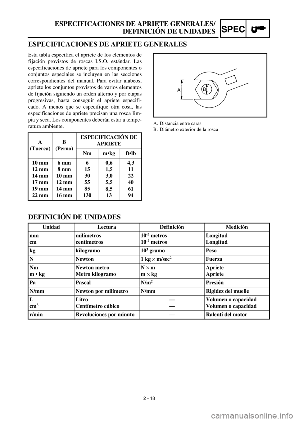
ESPECIFICACIONES DE APRIETE GENERALES/
DEFINICIÓN DE UNIDADES
ESPECIFICACIONES DE APRIETE GENERALES
A. Distancia entre caras
B. Diámetro exterior de la rosca
Esta tabla especifica el apriete de los elementos de
fijación provistos de roscas I.S.O. estándar. Las
especificaciones de apriete para los componentes o
conjuntos especiales se incluyen en las secciones
correspondientes del manual. Para evitar alabeos,
apriete los conjuntos provistos de varios elementos
de fijación siguiendo un orden alterno y por etapas
progresivas, hasta conseguir el apriete especifi-
cado. A menos que se especifique otra cosa, las
especificaciones de apriete precisan una rosca lim-
pia y seca. Los componentes deberán estar a tempe-
ratura ambiente.
A
(Tuerca)B
(Perno)ESPECIFICACIÓN DE
APRIETE
Nm m•kg ft•lb
10 mm
12 mm
14 mm
17 mm
19 mm
22 mm6 mm
8 mm
10 mm
12 mm
14 mm
16 mm6
15
30
55
85
1300,6
1,5
3,0
5,5
8,5
134,3
11
22
40
61
94
DEFINICIÓN DE UNIDADES
Unidad Lectura Definición Medición
mm
cmmilímetros
centímetros10
-3
metros
10
-2
metrosLongitud
Longitud
kg kilogramo 10
3
gramo Peso
N Newton 1 kg
´
m/sec
2
Fuerza
Nm
m • kgNewton metro
Metro kilogramoN
´
m
m
´
kgApriete
Apriete
Pa Pascal N/m
2
Presión
N/mm Newton por milímetro N/mm Rigidez del muelle
L
cm
3
Litro
Centímetro cúbico—
—Volumen o capacidad
Volumen o capacidad
r/min Revoluciones por minuto — Ralentí del motor
2 - 18
Page 144 of 654
2 - 19
SPEC
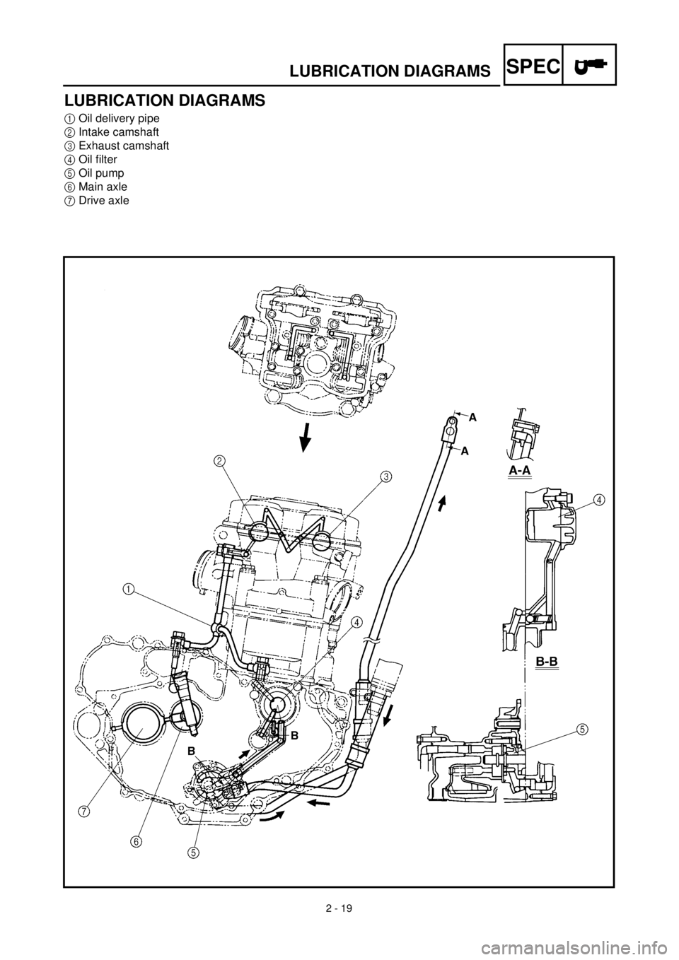
LUBRICATION DIAGRAMS
LUBRICATION DIAGRAMS
1
Oil delivery pipe
2
Intake camshaft
3
Exhaust camshaft
4
Oil filter
5
Oil pump
6
Main axle
7
Drive axle
Page 145 of 654

SPEC
SCHEMAS DE GRAISSAGE
SCHMIERSYSTEM-SCHAUBILDER
DIAGRAMAS DE LUBRICACIÓN
SCHMIERSYSTEM-
SCHAUBILDER
1
Ölzufuhrleitung
2
Einlaß-Nockenwelle
3
Auslaß-Nockenwelle
4
Ölfilter
5
Ölpumpe
6
Getriebe-Eingangswelle
7
Getriebe-Ausgangswelle
SCHEMAS DE GRAIS-
SAGE
1
Tuyau d’arrivée d’huile
2
Arbre à cames d’admission
3
Arbre à cames d’échappement
4
Filtre à huile
5
Pompe à huile
6
Arbre primaire
7
Arbre secondaire
2 - 19
DIAGRAMAS DE LUBRI-
CACIÓN
1
Tubo de distribución del aceite
2
Admisión del árbol de levas
3
Escape del árbol de levas
4
Filtro de aceite
5
Bomba de aceite
6
Eje principal
7
Eje de salida
Page 146 of 654
2 - 20
SPEC
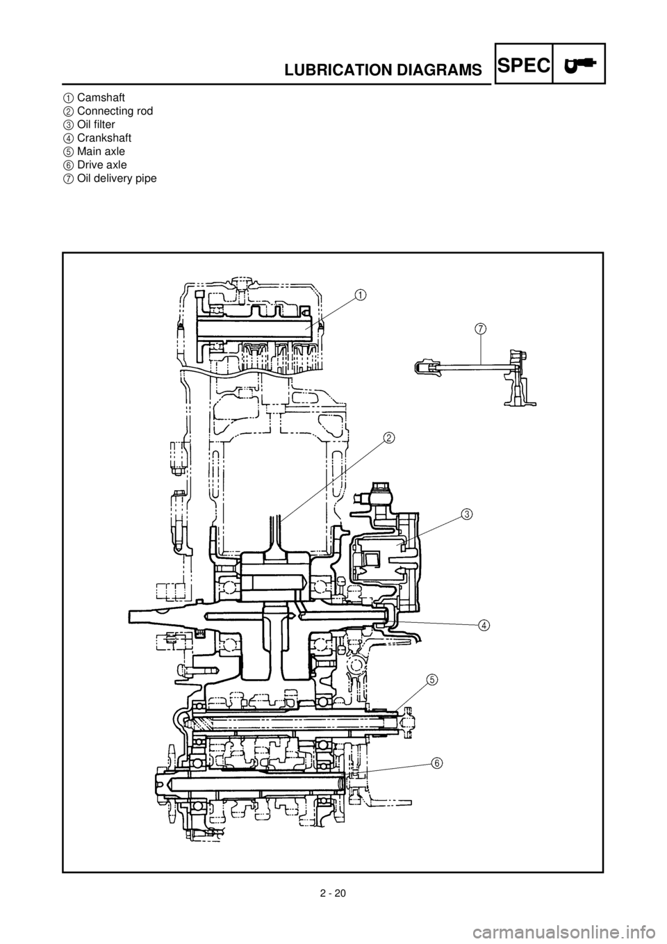
LUBRICATION DIAGRAMS
1
Camshaft
2
Connecting rod
3
Oil filter
4
Crankshaft
5
Main axle
6
Drive axle
7
Oil delivery pipe
Page 147 of 654

SPEC
SCHEMAS DE GRAISSAGE
SCHMIERSYSTEM-SCHAUBILDER
DIAGRAMAS DE LUBRICACIÓN
1
Nockenwelle
2
Pleuel
3
Ölfilter
4
Kurbelwelle
5
Getriebe-Eingangswelle
6
Getriebe-Ausgangswelle
7
Ölzufuhrleitung
1
Arbre à cames
2
Bielle
3
Filtre à huile
4
Vilebrequin
5
Arbre primaire
6
Arbre secondaire
7
Tuyau d’arrivée d’huile
2 - 20
1Árbol de levas
2Biela
3Filtro de aceite
4Arbol de levas
5Eje principal
6Eje de salida
7Tubo de distribución de aceite
Page 148 of 654

2 - 21
SPEC
CABLE ROUTING DIAGRAM
EC240000
CABLE ROUTING DIAGRAM
1
Hose guide
2
Brake hose
3
Regulator
4
Fuel tank breather hose
5
Oil tank breather hose
6
Clamp
7
“ENGINE STOP” button lead
8
Sub wire harness
9
Tail light lead
0
TPS (throttle position sensor) lead
A
Neutral switch lead
B
Oil hose
C
Cylinder head breather hose
D
CDI magneto lead
E
Hose holder
F
Clutch cable
G
Decompression cable
H
Lights switch lead
I
Carburetor breather hose
J
Overflow hose
K
Coolant reservoir tank breather hose
Pass the fuel tank breather
hose behind handlebar, then
insert it into the steering shaft
hole.
õ
Pass the decompression
cable, “ENGINE STOP” but-
ton lead and lights switch lead
under where the oil hose is
attached.
‚
Pass the “ENGINE STOP” but-
ton lead, regulator lead and
lights switch lead along the
inner and side of the decom-
pression cable.
ë
Fasten the CDI magneto lead,
neutral switch lead “ENGINE
STOP” button lead and lights
switch lead to the frame with a
plastic locking tie.äPass the “ENGINE STOP”
button lead and lights switch
lead along the inner side of
the oil tank breather hose.
ìFasten the sub wire harness,
“ENGINE STOP” button lead
and lights switch lead to the
frame with a plastic locking
tie.
íPass the cylinder head
breather hose along the right
side of the oil tank breather
hose.
îFasten the sub wire harness
to the frame with a plastic
locking tie and cut off the tie
end.
éFasten the TPS lead (in the
sub wire harness) under the
frame.
Page 149 of 654

SPEC
CHEMINEMENT DES CABLES
KABELFÜHRUNG
DIAGRAMA DE RUTA DE CABLES
KABELFÜHRUNG
1Kabelführung
2Bremsschlauch
3Regler
4Kraftstofftank-Belüftungsschlauch
5Öltank-Belüftungsschlauch
6Kabelbinder
7Motorstoppschalter-Kabel
8Nebenkabelsatz
9Rücklicht
0Drosselklappensensor-Kabel
ALeerlaufschalter-Kabel
BÖlschlauch
CZylinderkopf-Entlüftungsschlauch
DCDI-Schwungradmagnetzünder-Ka-
bel
ESchlauchhalterung
FKupplungszug
GDekompressionszug
HLichtschalterleitung
IVergaser-Entlüftungsschlauch
JAuslaufschutzschlauch
KKühlmittelausgleichstank-Lüftungs-
schlauch
Den Kraftstofftank-Belüftungs-
schlauch zwischen Lenker und Zugs-
trebe führen und das Ende durch die
Bohrung im Nummerschild führen.
õDen Dekompressionszug hinter dem
Öltank-Belüftungsschlauch und über
das Öltankrohr führen.
‚Das Motorstoppschalter-Kabel hinter
dem Dekompressionszug führen.
ëDas CDI-Schwungradmagnetzünder-
Kabel, Leerlaufschalter-Kabel und
Motorstoppschalter-Kabel mit wieder-
verwenden. Kabelbinder am Rahmen
befestigen.
äDas Motorstoppschalter-Kabel hinter
dem Öltank-Belüftungsschlauch füh-
ren.
ìDen Nebenkabelbaum und das Mo-
torstoppschalter-Kabel mit mehrf. ver-
wendb. Kabelbinder am Rahmen be-
festigen.
íDen Zylinderkopf-Entlüftungs-
schlauch rechts vom Öltank-Belüf-
tungsschlauch führen.
îDen Nebenkabelbaum mit einem Ka-
belbinder am Rahmen befestigen,
und das Schlauchbandende ab-
schneiden.
éDie TPS-Leitung (im Nebenkabel-
baum) unter dem Rahmen verlegen.
CHEMINEMENT DES
CABLES
1Guide de flexible
2Tuyau de frein
3Régulateur
4Reniflard de réservoir d’essence
5Reniflard de réservoir d’huile
6Bride
7Fil de bouton d’arrêt du moteur
“ENGINE STOP”
8Faisceau de fils secondaires
9Fil de feux arrière
0Fil de TPS (copteur du papillon d’accélé-
ration)
AFil de contacteur de point mort
BFlexible d’huile
CReniflard de culasse
DFil de magnéto CDI
ESupport de flexible
FCâble d’embrayage
GCâble du décompresseur
HFil de commutateur de feux
IReniflard de carburateur
JFlexible de trop-plein
KFlexible de reniflard du réservoir de
liquide de refroidissement
Faire passer le flexible de reniflard du
réservoir d’essence derrière le guidon,
puis l’insérer dans le trou de l’axe de la
colonne de direction.
õFaire passer le câble de décompression, le
fil de bouton d’arrêt du moteur “ENGINE
STOP” et le fil de commutateur de feux
sous l’endroit où le flexible d’huile est
attaché.
‚Faire passer le fil de bouton d’arrêt du
moteur “ENGINE STOP”, le fil de régu-
lateur et le fil de commutateur de feux le
long du côté intérieur du câble de décom-
pression.
ëAttacher le fil de magnéto CDI, le fil de
commutateur de point mort, le fil du bou-
ton d’arrêt du moteur “ENGINE STOP”
et le fil de commutateur de feux au cadre
à l’aide d’une attache en plastique.
äFaire passer le fil de bouton d’arrêt du
moteur “ENGINE STOP” et le fil de com-
mutateur de feux le long du côté intérieur
du flexible de reniflard du réservoir
d’huile.
ìAttacher le faisceau de fils secondaires, le
fil de bouton d’arrêt du moteur “ENGINE
STOP” et le fil de commutateur de feux
au cadre à l'aide d’une attache en plasti-
que.
íFaire passer le reniflard de culasse le long
du côté droit du reniflard du réservoir
d’huile.
îAttacher le faisceau de fils secondaires au
cadre à l’aide d’une attache en plastique
et couper l’extrémité de l’attache.
éAttacher le fil de TPS (dans le faisceau de
fils secondaires) sous le cadre.
2 - 21
DIAGRAMA DE RUTA DE
CABLES
1Guía del tubo
2Tubo del freno
3Regulador
4Tubo respiradero del depósito de combus-
tible
5Tubo respiradero del depósito de aceite
6Abrazadera
7Cable del botón de parada del motor
“ENGINE STOP”
8Sub-cableado
9Cable de la luz trasera
0Cable TPS (sensor de posición del acele-
rador)
ACable del interruptor de punto muerto
BTubo de aceite
CTubo respiradero de la culata
DCable del magneto CDI
ESoporte del tubo
FCable del embrague
GCable de descompresión
HCable del interruptor de las luces
ITubo respiradero del carburador
JTubo de desbordamiento
KTubo respiradero del depósito de reserva
del refrigerante
Pasar el tubo respiradero del depósito de
combustible por detrás del manillar y des-
pués insertarlo en del orificio del eje de la
dirección.
õPasar el cable de descompresión, el cable
del botón de parada del motor “ENGINE
STOP” y el cable del interruptor de las
luces por debajo de la zona de colocación
del tubo de aceite.
‚Pasar el cable del botón de parada del
motor “ENGINE STOP”, el cable del
regulador y el cable del interruptor de las
luces por la parte interna y lateral del
cable de descompresión.
ëSujetar el cable del magneto CDI, el cable
del interruptor de punto muerto, el cable
del botón de parada del motor “ENGINE
STOP” y el cable del interruptor de las
luces al bastidor mediante una conexión
plástica de cierre.
äPasar el cable del botón de parada del
motor “ENGINE STOP” y el cable del
interruptor de las luces por la parte interna
lateral del tubo respiradero del depósito
de aceite.
ìSujetar el sub-cableado, el cable del botón
de parada del motor “ENGINE STOP” y
el cable del interruptor de las luces al bas-
tidor mediante una conexión plástica de
cierre.
íPasar el tubo respiradero de la culata por
el lado derecho del tubo respiradero del
depósito de aceite.
îSujetar el sub-cableado al bastidor
mediante una conexión plástica de cierre
y cortar el extremo de la conexión.
éSujetar el cable TPS (del sub-cableado)
por debajo del bastidor.
Page 150 of 654
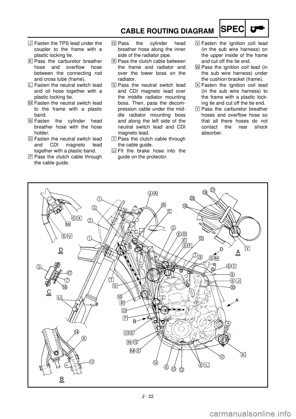
2 - 22
SPECCABLE ROUTING DIAGRAM
ïFasten the TPS lead under the
coupler to the frame with a
plastic locking tie.
ðPass the carburetor breather
hose and overflow hose
between the connecting rod
and cross tube (frame).
ñFasten the neutral switch lead
and oil hose together with a
plastic locking tie.
÷Fasten the neutral switch lead
to the frame with a plastic
band.
öFasten the cylinder head
breather hose with the hose
holder.
¯Fasten the neutral switch lead
and CDI magneto lead
together with a plastic band.
¸Pass the clutch cable through
the cable guide.ÎPass the cylinder head
breather hose along the inner
side of the radiator pipe.
åPass the clutch cable between
the frame and radiator and
over the lower boss on the
radiator.
êPass the neutral switch lead
and CDI magneto lead over
the middle radiator mounting
boss. Then, pass the decom-
pression cable under the mid-
dle radiator mounting boss
and along the left side of the
neutral switch lead and CDI
magneto lead.
æPass the clutch cable through
the cable guide.
èFit the brake hose into the
guide on the protector.×Fasten the ignition coil lead
(in the sub wire harness) on
the upper inside of the frame
and cut off the tie end.
ãPass the ignition coil lead (in
the sub wire harness) under
the cushion bracket (frame).
ÅFasten the ignition coil lead
(in the sub wire harness) to
the frame with a plastic lock-
ing tie and cut off the tie end.
çPass the carburetor breather
hoses and overflow hose so
that all there hoses do not
contact the rear shock
absorber.