YAMAHA WR 450F 2006 Owners Manual
Manufacturer: YAMAHA, Model Year: 2006, Model line: WR 450F, Model: YAMAHA WR 450F 2006Pages: 786, PDF Size: 22.49 MB
Page 731 of 786

–+ELEC
SISTEMA DE SEÑALIZACIÓN
PROCEDIMIENTO DE REVISIÓN
Si el velocímetro no funciona utilice el procedimiento de comprobación siguiente.
*1 marcado: Consulte el apartado “COMPROBACIÓN Y CARGA DE LA BATERÍA” del CAPÍTULO 3.
NOTA:
Desmontar las piezas siguientes antes de proceder a la revisión.
1) Faro
Utilice las herramientas especiales siguientes en esta revisión.
Comprobador de bolsillo:
YU-3112-C/90890-03112
*1 Comprobar batería. Recargar o cambiar.
Comprobar todos los acopla-
dores y conexiones de cables.Reparar o cambiar.
Comprobar el visor multifun-
ción.Voltaje de
entradaCambiar el mazo de
cables.
Voltaje de
salidaCambiar el visor multi-
función.
Comprobar el sensor de velo-
cidad.Cambiar.
Correcto
Correcto
Correcto
Incorrecto
Incorrecto
Incorrecto Incorrecto
Incorrecto
SISTEMA DE SEÑALIZACIÓN
6 - 26
Page 732 of 786

6 - 27
–+ELECSIGNALING SYSTEM
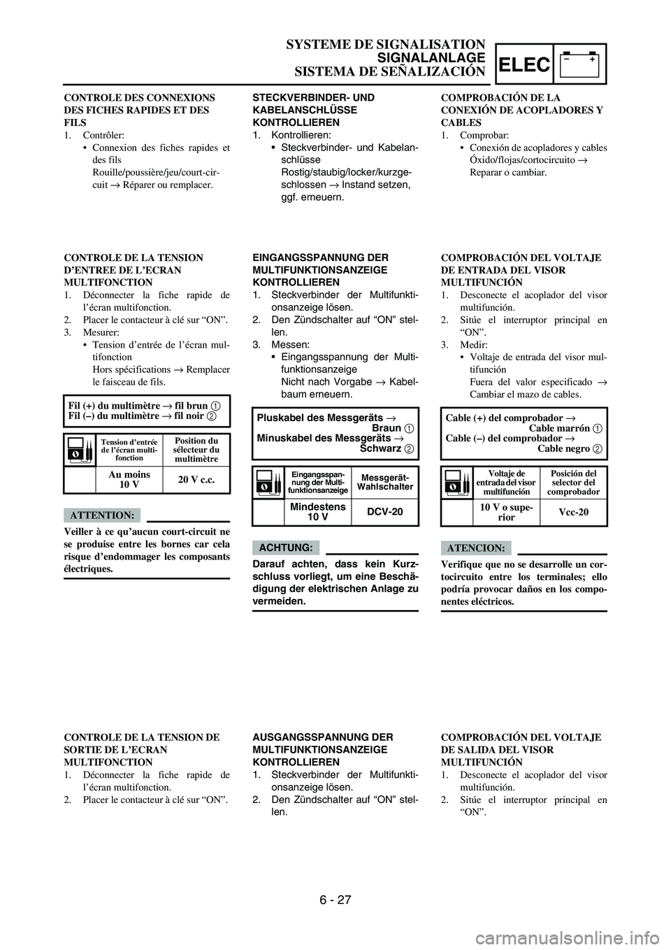
COUPLERS AND LEADS CONNECTION
INSPECTION
1. Check:
•Couplers and leads connection
Rust/dust/looseness/short-circuit →
Repair or replace.
MULTI-FUNCTION DISPLAY INPUT
VOLTAGE INSPECTION
1. Disconnect the multi-function display cou-
pler.
2. Set the main switch to “ON”.
3. Measure:
•Multi-function display input voltage
Out of specification → Replace wire har-
ness.
CAUTION:
Make sure that a short-circuit does not
develop between the terminals because it
may cause damage to electrical compo-
nents.Tester (+) lead
→ Brown lead
1
Tester (–) lead
→ Black lead
2
Multi-function dis-
play input voltageTester selec-
tor position
10 V or more DCV-20
MULTI-FUNCTION DISPLAY OUTPUT
VOLTAGE INSPECTION
1. Disconnect the multi-function display cou-
pler.
2. Set the main switch to “ON”.
Page 733 of 786

–+ELEC
STECKVERBINDER- UND
KABELANSCHLÜSSE
KONTROLLIEREN
1. Kontrollieren:
Steckverbinder- und Kabelan-
schlüsse
Rostig/staubig/locker/kurzge-
schlossen → Instand setzen,
ggf. erneuern.
EINGANGSSPANNUNG DER
MULTIFUNKTIONSANZEIGE
KONTROLLIEREN
1. Steckverbinder der Multifunkti-
onsanzeige lösen.
2. Den Zündschalter auf “ON” stel-
len.
3. Messen:
Eingangsspannung der Multi-
funktionsanzeige
Nicht nach Vorgabe → Kabel-
baum erneuern.
ACHTUNG:
Darauf achten, dass kein Kurz-
schluss vorliegt, um eine Beschä-
digung der elektrischen Anlage zu
vermeiden.Pluskabel des Messgeräts →
Braun 1
Minuskabel des Messgeräts →
Schwarz 2
Eingangsspan-
nung der Multi-
funktionsanzeigeMessgerät-
Wahlschalter
Mindestens
10 VDCV-20
AUSGANGSSPANNUNG DER
MULTIFUNKTIONSANZEIGE
KONTROLLIEREN
1. Steckverbinder der Multifunkti-
onsanzeige lösen.
2. Den Zündschalter auf “ON” stel-
len. CONTROLE DES CONNEXIONS
DES FICHES RAPIDES ET DES
FILS
1. Contrôler:
Connexion des fiches rapides et
des fils
Rouille/poussière/jeu/court-cir-
cuit → Réparer ou remplacer.
CONTROLE DE LA TENSION
D’ENTREE DE L’ECRAN
MULTIFONCTION
1. Déconnecter la fiche rapide de
l’écran multifonction.
2. Placer le contacteur à clé sur “ON”.
3. Mesurer:
Tension d’entrée de l’écran mul-
tifonction
Hors spécifications → Remplacer
le faisceau de fils.
ATTENTION:
Veiller à ce qu’aucun court-circuit ne
se produise entre les bornes car cela
risque d’endommager les composants
électriques.Fil (+) du multimètre → fil brun 1
Fil (–) du multimètre → fil noir 2
Tension d’entrée
de l’écran multi-
fonctionPosition du
sélecteur du
multimètre
Au moins
10 V20 V c.c.
CONTROLE DE LA TENSION DE
SORTIE DE L’ECRAN
MULTIFONCTION
1. Déconnecter la fiche rapide de
l’écran multifonction.
2. Placer le contacteur à clé sur “ON”.COMPROBACIÓN DE LA
CONEXIÓN DE ACOPLADORES Y
CABLES
1. Comprobar:
Conexión de acopladores y cables
Óxido/flojas/cortocircuito →
Reparar o cambiar.
COMPROBACIÓN DEL VOLTAJE
DE ENTRADA DEL VISOR
MULTIFUNCIÓN
1. Desconecte el acoplador del visor
multifunción.
2. Sitúe el interruptor principal en
“ON”.
3. Medir:
Voltaje de entrada del visor mul-
tifunción
Fuera del valor especificado →
Cambiar el mazo de cables.
ATENCION:
Verifique que no se desarrolle un cor-
tocircuito entre los terminales; ello
podría provocar daños en los compo-
nentes eléctricos. Cable (+) del comprobador →
Cable marrón 1
Cable (–) del comprobador →
Cable negro 2
Voltaje de
entrada del visor
multifunciónPosición del
selector del
comprobador
10 V o supe-
riorVcc-20
COMPROBACIÓN DEL VOLTAJE
DE SALIDA DEL VISOR
MULTIFUNCIÓN
1. Desconecte el acoplador del visor
multifunción.
2. Sitúe el interruptor principal en
“ON”.
SYSTEME DE SIGNALISATION
SIGNALANLAGE
SISTEMA DE SEÑALIZACIÓN
6 - 27
Page 734 of 786

6 - 28
–+ELECSIGNALING SYSTEM
3. Measure:
•Multi-function display output voltage
Out of specification → Replace multi-
function display.
CAUTION:
Make sure that a short-circuit does not
develop between the terminals because it
may cause damage to electrical compo-
nents.Tester (+) lead
→ Red lead
1
Tester (–) lead
→ Black/White lead
2
Multi-function dis-
play output voltageTester selec-
tor position
4.5 V or more DCV-20
SPEED SENSOR OUTPUT VOLTAGE
INSPECTION
1. Insert the thin electric conductors 1 (lead)
into the speed sensor coupler 2, as
shown, and connect the tester to them.
CAUTION:
Do not insert the electric conductors
more than required because it may
reduce the waterproof function of the
coupler.
Make sure that a short-circuit does not
develop between the terminals because it
may cause damage to electrical compo-
nents.
2. Set the main switch to “ON”. Tester (+) lead
→ White lead
3
Tester (–) lead
→ Black lead
4
Page 735 of 786

–+ELEC
3. Messen:
Ausgangsspannung der Multi-
funktionsanzeige
Nicht nach Vorgabe → Multi-
funktionsanzeige erneuern.
ACHTUNG:
Darauf achten, dass kein Kurz-
schluss vorliegt, um eine Beschä-
digung der elektrischen Anlage zu
vermeiden.Pluskabel des Messgeräts →
Rot 1
Minuskabel des Messgeräts →
Schwarz/Weiß 2
Ausgangsspan-
nung der Multi-
funktionsanzeigeMessgerät-
Wahlschalter
Mindestens
4,5 VDCV-20
AUSGANGSSPANNUNG DES
GESCHWINDIGKEITSSENSORS
KONTROLLIEREN
1. Dünne Kabel 2, wie in der
Abbildung gezeigt, in den
Geschwindigkeitssensor-Steck-
verbinder 1 stecken und dann
das Messgerät an die Kabel
anschließen.
ACHTUNG:
Die Kabel nicht tiefer als not-
wendig in den Steckverbinder
stecken, um dessen Wasser-
dichtigkeit nicht zu beeinträchti-
gen.
Darauf achten, dass kein Kurz-
schluss vorliegt, um eine
Beschädigung der elektrischen
Anlage zu vermeiden.
2. Den Zündschalter auf “ON” stel-
len. Pluskabel des Messgeräts →
Weiß 3
Minuskabel des Messgeräts →
Schwarz 4
3. Mesurer:
Tension de sortie de l’écran mul-
tifonction
Hors spécifications → Remplacer
l’écran multifonction.
ATTENTION:
Veiller à ce qu’aucun court-circuit ne
se produise entre les bornes car cela
risque d’endommager les composants
électriques.Fil (+) du multimètre → fil rouge 1
Fil (–) du multimètre →
fil noir/blanc 2
Tension de sortie
de l’écran multi-
fonctionPosition du
sélecteur du
multimètre
Au moins 4,5
V20 V c.c.
CONTROLE DE LA TENSION DE
SORTIE DU CAPTEUR DE
VITESSE
1. Introduire les fins conducteurs élec-
triques 1 (fils) dans la fiche rapide
du capteur de vitesse 2, comme
illustré, et y raccorder le multimè-
tre.
ATTENTION:
Ne pas enfoncer les conducteurs
électriques plus que nécessaire; cela
risque en effet de réduire l’étan-
chéité de la fiche rapide.
Veiller à ce qu’aucun court-circuit
ne se produise entre les bornes car
cela risque d’endommager les com-
posants électriques.
2. Placer le contacteur à clé sur “ON”. Fil (+) du multimètre → fil blanc 3
Fil (–) du multimètre → fil noir 4
3. Medir:
Voltaje de salida del visor multi-
función
Fuera del valor especificado →
Cambiar el visor multifunción.
ATENCION:
Verifique que no se desarrolle un cor-
tocircuito entre los terminales; ello
podría provocar daños en los compo-
nentes eléctricos. Cable (+) del comprobador →
Cable rojo 1
Cable (–) del comprobador →
Cable negro/blanco 2
Voltaje de salida
del visor multi-
funciónPosición del
selector del
comprobador
4,5 V o supe-
riorVcc-20
COMPROBACIÓN DEL VOLTAJE
DE SALIDA DEL SENSOR DE
VELOCIDAD
1. Introduzca los conductores eléctri-
cos finos 1 (cable) en el acoplador
del sensor de velocidad 2, como se
muestra, y conecte el comprobador.
ATENCION:
No introduzca los conductores eléc-
tricos más de lo necesario, pues se
puede reducir la estanqueidad del
acoplador.
Verifique que no se desarrolle un
cortocircuito entre los terminales;
ello podría provocar daños en los
componentes eléctricos.
2. Sitúe el interruptor principal en
“ON”. Cable (+) del comprobador →
Cable blanco 3
Cable (–) del comprobador →
Cable negro 4
SYSTEME DE SIGNALISATION
SIGNALANLAGE
SISTEMA DE SEÑALIZACIÓN
6 - 28
Page 736 of 786

6 - 29
–+ELECSIGNALING SYSTEM
3. Measure:
•Speed sensor output voltage
Output voltage not correct → Replace the
speed sensor.
Measurement steps:
•Elevate the front wheel and slowly rotate
it.
•Measure the voltage (DCV) of white lead
and black lead. With each full rotation of
the front wheel, the voltage reading should
cycle from 0.6 V to 4.8 V to 0.6 V to 4.8 V.
Page 737 of 786

–+ELEC
3. Messen:
Geschwindigkeitssensor-Aus-
gangsspannung
Nicht nach Vorgabe →
Geschwindigkeitssensor
erneuern.
Messung:
Das Vorderrad anheben und
langsam drehen.
Die Spannung (DCV) zwischen
Weiß und Schwarz messen.
Mit jeder Umdrehung des Hin-
terrads sollte das Messergeb-
nis folgendermaßen wechseln:
0,6 V – 4,8 V – 0,6 V – 4,8 V.3. Mesurer:
Tension de sortie du capteur de
vitesse
Tension de sortie incorrecte →
Remplacer le capteur de vitesse.
Procédure de mesure:
Relever la roue avant et la faire
tourner doucement.
Mesurer la tension (V c.c.) des fils
blanc et noir. A chaque rotation com-
plète de la roue avant, la mesure de la
tension doit effectuer le cycle sui-
vant: 0,6 V - 4,8 V - 0,6 V - 4,8 V.3. Medir:
Voltaje de salida del sensor de
velocidad
Voltaje de salida incorrecto →
Cambiar el sensor de velocidad.
Procedimiento de medición:
Levante la rueda delantera y gírela
lentamente.
Mida el voltaje (Vcc) del cable
blanco y del cable negro. Con cada
vuelta completa de la rueda delan-
tera, la lectura de voltaje debe pasar
cíclicamente de 0,6 V a 4,8 V, a
0,6 V y a 4,8 V.
SYSTEME DE SIGNALISATION
SIGNALANLAGE
SISTEMA DE SEÑALIZACIÓN
6 - 29
Page 738 of 786

7 - 1
TUN
EC700000
TUNING
EC710000
ENGINE
Carburetor setting
•The air/fuel mixture will vary depending on
atmospheric conditions. Therefore, it is nec-
essary to take into consideration the air pres-
sure, ambient temperature, humidity, etc.,
when adjusting the carburetor.
•Perform a test run to check for proper engine
performance (e.g., throttle response) and
spark plug(-s) discoloration or fouling. Use
these readings to determine the best possi-
ble carburetor setting.
NOTE:
It is recommended to keep a record of all car-
buretor settings and external conditions (e.g.,
atmospheric conditions, track/surface condi-
tions, lap times) to make future carburetor set-
ting easier.
WARNING
The carburetor is a part of the fuel line.
Therefore, be sure to install it in a well-
ventilated area, away from flammable
objects and any sources of fire.
Never look into the carburetor intake.
Flames may shoot out from the pipe if the
engine backfires while it is being started.
Gasoline may be discharged from the
accelerator pump nozzle when the carbu-
retor has been removed.
SETTING
Page 739 of 786

TUN
ABSTIMMUNG
MOTOR
Vergaser-Abstimmung
Das Gemisch hängt u. a. von den
atmosphärischen Bedingungen ab.
Luftdruck, -temperatur und -feuch-
tigkeit sind Faktoren, die bei der
Vergaser-Abstimmung mit in
Betracht gezogen werden müssen.
Die Leistung und das Ansprech-
verhalten des Motors sowie der
Zustand der Kerze lassen sich am
besten im einem Testlauf prüfen.
Anhand dieser Ergebnisse kann
der Vergaser optimal eingestellt
werden.
HINWEIS:
Es empfiehlt sich, die jeweiligen
Umstände (atmosphärische Bedin-
gungen, Fahrbahnzustand, Anzahl
Runden usw.) und die entsprechen-
den Vergaser-Einstellungen zwecks
späterer Bezugnahme aufzuzeich-
nen.
WARNUNG
Der Vergaser ist ein Bestandteil
des Kraftstoffsystems. Bei
Arbeiten daher stets auf eine
gute Belüftung sorgen und Feu-
erquellen sowie entzündliche
Stoffe fern halten.
Niemals in den Vergasereinlass
hineinblikken. Beim Starten des
Motors könnten Flammen rück-
schlagen. Auch bei ausgebau-
tem Vergaser könnte Benzin aus
der Beschleunigungspumpe
entweichen.
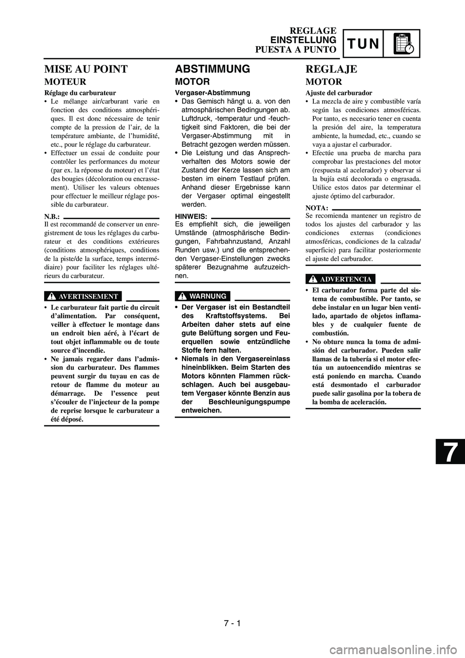
MISE AU POINT
MOTEUR
Réglage du carburateur
Le mélange air/carburant varie en
fonction des conditions atmosphéri-
ques. Il est donc nécessaire de tenir
compte de la pression de l’air, de la
température ambiante, de l’humidité,
etc., pour le réglage du carburateur.
Effectuer un essai de conduite pour
contrôler les performances du moteur
(par ex. la réponse du moteur) et l’état
des bougies (décoloration ou encrasse-
ment). Utiliser les valeurs obtenues
pour effectuer le meilleur réglage pos-
sible du carburateur.
N.B.:
Il est recommandé de conserver un enre-
gistrement de tous les réglages du carbu-
rateur et des conditions extérieures
(conditions atmosphériques, conditions
de la piste/de la surface, temps intermé-
diaire) pour faciliter les réglages ulté-
rieurs du carburateur.
AVERTISSEMENT
Le carburateur fait partie du circuit
d’alimentation. Par conséquent,
veiller à effectuer le montage dans
un endroit bien aéré, à l’écart de
tout objet inflammable ou de toute
source d’incendie.
Ne jamais regarder dans l’admis-
sion du carburateur. Des flammes
peuvent surgir du tuyau en cas de
retour de flamme du moteur au
démarrage. De l’essence peut
s’écouler de l’injecteur de la pompe
de reprise lorsque le carburateur a
été déposé.
REGLAJE
MOTOR
Ajuste del carburador
La mezcla de aire y combustible varía
según las condiciones atmosféricas.
Por tanto, es necesario tener en cuenta
la presión del aire, la temperatura
ambiente, la humedad, etc., cuando se
vaya a ajustar el carburador.
Efectúe una prueba de marcha para
comprobar las prestaciones del motor
(respuesta al acelerador) y observar si
la bujía está decolorada o engrasada.
Utilice estos datos par determinar el
ajuste óptimo del carburador.
NOTA:
Se recomienda mantener un registro de
todos los ajustes del carburador y las
condiciones externas (condiciones
atmosféricas, condiciones de la calzada/
superficie) para facilitar posteriormente
el ajuste del carburador.
ADVERTENCIA
El carburador forma parte del sis-
tema de combustible. Por tanto, se
debe instalar en un lugar bien venti-
lado, apartado de objetos inflama-
bles y de cualquier fuente de
combustión.
No obture nunca la toma de admi-
sión del carburador. Pueden salir
llamas de la tubería si el motor efec-
túa un autoencendido mientras se
está poniendo en marcha. Cuando
está desmontado el carburador
puede salir gasolina por la tobera de
la bomba de aceleración.
REGLAGE
EINSTELLUNG
PUESTA A PUNTO
7 - 1
7
Page 740 of 786

7 - 2
TUN
CAUTION:
The carburetor is extremely sensitive to
foreign matter (dirt, sand, water, etc.).
During installation, do not allow foreign
matter to get into the carburetor.
Always handle the carburetor and its
components carefully. Even slight
scratches, bends or damage to carburetor
parts may prevent the carburetor from
functioning correctly. Carefully perform
all servicing with the appropriate tools
and without applying excessive force.
When the engine is stopped or when
riding at no load, do not open and close
the throttle unnecessarily. Otherwise, too
much fuel may be discharged, starting
may become difficult or the engine may
not run well.
After installing the carburetor, check that
the throttle operates correctly and opens
and closes smoothly.
Atmospheric conditions and carburetor
settings
The air density (i.e., concentration of oxygen
in the air) determines the richness or lean-
ness of the air/fuel mixture. Therefore, refer
to the above table for mixture settings.
That is:
•Higher temperature expands the air with its
resultant reduced density.
•Higher humidity reduces the amount of oxy-
gen in the air by so much of the water vapor
in the same air.
•Lower atmospheric pressure (at a high alti-
tude) reduces the density of the air.
Air temp. HumidityAir
pressure
(altitude)Mixture Setting
High High Low (high) Richer Leaner
Low Low High (low) Leaner Richer
SETTING