YAMAHA WR 450F 2007 Betriebsanleitungen (in German)
Manufacturer: YAMAHA, Model Year: 2007, Model line: WR 450F, Model: YAMAHA WR 450F 2007Pages: 794, PDF-Größe: 21.82 MB
Page 171 of 794
2 - 21
SPEC
SCHMIERSYSTEM-
SCHAUBILDER
1Ölfiltereinsatz
2Ölpumpe
3Ausgangswelle
4Eingangswelle
5Kurbelwelle
6Übertragungshebel
ÈVom Zylinder
ÉZum Öltank
DIAGRAMMES DE
LUBRIFICATION
1Elément de filtre à huile
2Pompe à huile
3Arbre secondaire
4Arbre primaire
5Vilebrequin
6Bielle
ÈDu cylindre
ÉVers le réservoir d’huile
DIAGRAMAS DE
ENGRASE
1Elemento del filtro de aceite
2Bomba de aceite
3Eje posterior
4Eje principal
5Cigüeñal
6Biela
ÈDel cilindro
ÉAl depósito de aceite
DIAGRAMMES DE LUBRIFICATION
SCHMIERSYSTEM-SCHAUBILDER
DIAGRAMAS DE ENGRASE
Page 172 of 794
2 - 22
SPECLUBRICATION DIAGRAMS
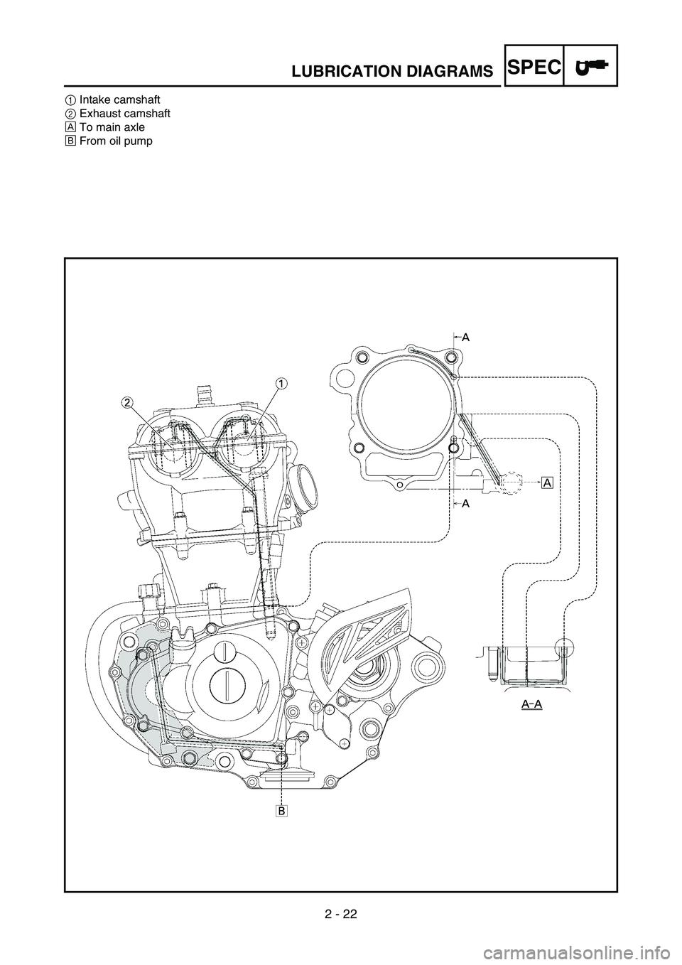
1Intake camshaft
2Exhaust camshaft
ÈTo main axle
ÉFrom oil pump
Page 173 of 794

2 - 22
SPEC
1Einlass-Nockenwelle
2Auslass-Nockenwelle
ÈZur Getriebe-Eingangswelle
ÉVon der Ölpumpe 1Arbre à cames d’admission
2Arbre à cames d’échappement
ÈVers l’arbre primaire
ÉDe la pompe à huile1Eje de levas de admisión
2Eje de levas de escape
ÈAl eje principal
ÉDe la bomba de aceite
DIAGRAMMES DE LUBRIFICATION
SCHMIERSYSTEM-SCHAUBILDER
DIAGRAMAS DE ENGRASE
Page 174 of 794
2 - 23
SPECCABLE ROUTING DIAGRAM
EC240000
CABLE ROUTING DIAGRAM
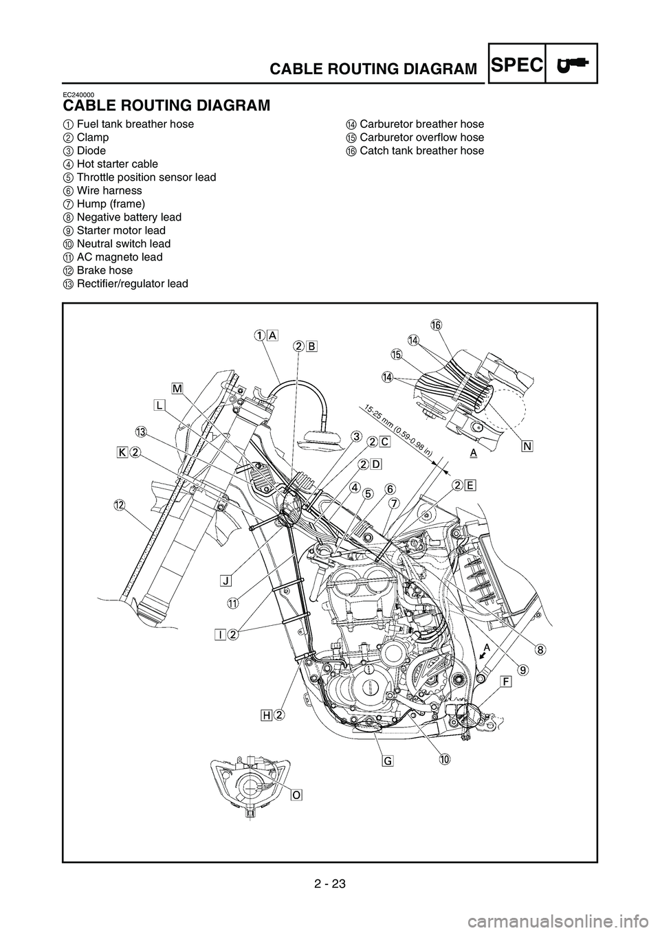
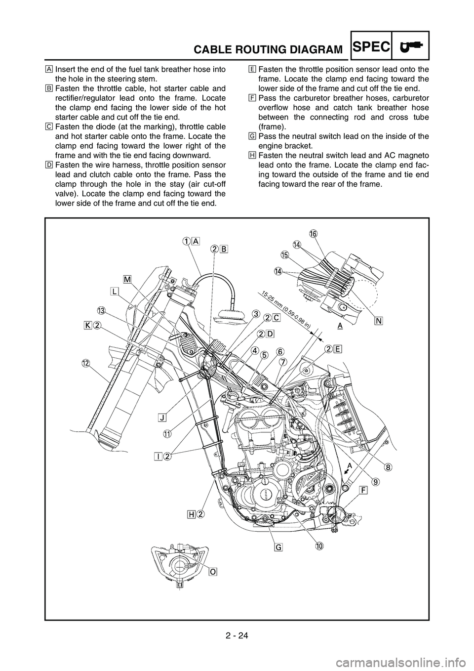
1Fuel tank breather hose
2Clamp
3Diode
4Hot starter cable
5Throttle position sensor lead
6Wire harness
7Hump (frame)
8Negative battery lead
9Starter motor lead
0Neutral switch lead
AAC magneto lead
BBrake hose
CRectifier/regulator leadDCarburetor breather hose
ECarburetor overflow hose
FCatch tank breather hose
Page 175 of 794
2 - 23
SPEC
KABELFÜHRUNGS-
SCHAUBILD
1Kraftstofftank-Belüftungsschlauch
2Klemme
3Diode
4Warmstartzug
5Drosselklappensensor-Kabel
6Kabelbaum
7Buckel (Rahmen)
8Batterie-Minuskabel
9Starter-Kabel
0Leerlaufschalter-Kabel
ALichtmaschinen-Kabel
BBremsschlauch
CGleichrichter/Regler-Kabel
DVergaser-Entlüftungsschlauch
EVergaser-Überlaufschlauch
FAuffangtank-Belüftungsschlauch
DIAGRAMME DE
CHEMINEMENT DES
CABLES
1Durit de mise à l’air du réservoir de car-
burant
2Collier à pince
3Diode
4Câble de starter à chaud
5Fil du capteur de position de papillon des
gaz
6Faisceau de fils
7Bosse (cadre)
8Câble négatif de batterie
9Fil du démarreur
0Fil du contacteur de point mort
AFil de l’alternateur avec rotor à aimanta-
tion permanente
BDurit de frein
CFil du redresseur/régulateur
DDurit de mise à l’air du carburateur
EDurit de trop-plein du carburateur
FDurit de mise à l’air du réservoir de récu-
pération
DIAGRAMA DE
CABLEADO
1Tubo respiradero del depósito de combus-
tible
2Brida
3Diodo
4Cable de arranque en caliente
5Cable del sensor de posición del acelera-
dor
6Mazo de cables
7Montículo (bastidor)
8Cable negativo de la batería
9Cable del motor de arranque
0Cable del interruptor de luz de punto
muerto
ACable de la magneto CA
BTubo de freno
CCable del rectificador/regulador
DTubo respiradero del carburador
ETubo de desbordamiento del carburador
FTubo respiradero del depósito de recupe-
ración
DIAGRAMME DE CHEMINEMENT DES CABLES
KABELFÜHRUNGS-SCHAUBILD
DIAGRAMA DE CABLEADO
Page 176 of 794
2 - 24
SPECCABLE ROUTING DIAGRAM
ÈInsert the end of the fuel tank breather hose into
the hole in the steering stem.
ÉFasten the throttle cable, hot starter cable and
rectifier/regulator lead onto the frame. Locate
the clamp end facing the lower side of the hot
starter cable and cut off the tie end.
ÊFasten the diode (at the marking), throttle cable
and hot starter cable onto the frame. Locate the
clamp end facing toward the lower right of the
frame and with the tie end facing downward.
ËFasten the wire harness, throttle position sensor
lead and clutch cable onto the frame. Pass the
clamp through the hole in the stay (air cut-off
valve). Locate the clamp end facing toward the
lower side of the frame and cut off the tie end.ÌFasten the throttle position sensor lead onto the
frame. Locate the clamp end facing toward the
lower side of the frame and cut off the tie end.
ÍPass the carburetor breather hoses, carburetor
overflow hose and catch tank breather hose
between the connecting rod and cross tube
(frame).
ÎPass the neutral switch lead on the inside of the
engine bracket.
ÏFasten the neutral switch lead and AC magneto
lead onto the frame. Locate the clamp end fac-
ing toward the outside of the frame and tie end
facing toward the rear of the frame.
Page 177 of 794
2 - 24
SPEC
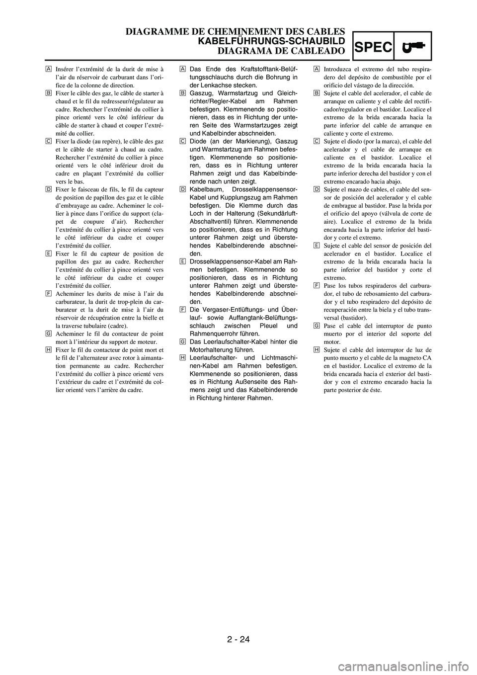
ÈDas Ende des Kraftstofftank-Belüf-
tungsschlauchs durch die Bohrung in
der Lenkachse stecken.
ÉGaszug, Warmstartzug und Gleich-
richter/Regler-Kabel am Rahmen
befestigen. Klemmenende so positio-
nieren, dass es in Richtung der unte-
ren Seite des Warmstartzuges zeigt
und Kabelbinder abschneiden.
ÊDiode (an der Markierung), Gaszug
und Warmstartzug am Rahmen befes-
tigen. Klemmenende so positionie-
ren, dass es in Richtung unterer
Rahmen zeigt und das Kabelbinde-
rende nach unten zeigt.
ËKabelbaum, Drosselklappensensor-
Kabel und Kupplungszug am Rahmen
befestigen. Die Klemme durch das
Loch in der Halterung (Sekundärluft-
Abschaltventil) führen. Klemmenende
so positionieren, dass es in Richtung
unterer Rahmen zeigt und überste-
hendes Kabelbinderende abschnei-
den.
ÌDrosselklappensensor-Kabel am Rah-
men befestigen. Klemmenende so
positionieren, dass es in Richtung
unterer Rahmen zeigt und überste-
hendes Kabelbinderende abschnei-
den.
ÍDie Vergaser-Entlüftungs- und Über-
lauf- sowie Auffangtank-Belüftungs-
schlauch zwischen Pleuel und
Rahmenquerrohr führen.
ÎDas Leerlaufschalter-Kabel hinter die
Motorhalterung führen.
ÏLeerlaufschalter- und Lichtmaschi-
nen-Kabel am Rahmen befestigen.
Klemmenende so positionieren, dass
es in Richtung Außenseite des Rah-
mens zeigt und das Kabelbinderende
in Richtung hinterer Rahmen. ÈInsérer l’extrémité de la durit de mise à
l’air du réservoir de carburant dans l’ori-
fice de la colonne de direction.
ÉFixer le câble des gaz, le câble de starter à
chaud et le fil du redresseur/régulateur au
cadre. Rechercher l’extrémité du collier à
pince orienté vers le côté inférieur du
câble de starter à chaud et couper l’extré-
mité du collier.
ÊFixer la diode (au repère), le câble des gaz
et le câble de starter à chaud au cadre.
Rechercher l’extrémité du collier à pince
orienté vers le côté inférieur droit du
cadre en plaçant l’extrémité du collier
vers le bas.
ËFixer le faisceau de fils, le fil du capteur
de position de papillon des gaz et le câble
d’embrayage au cadre. Acheminer le col-
lier à pince dans l’orifice du support (cla-
pet de coupure d’air). Rechercher
l’extrémité du collier à pince orienté vers
le côté inférieur du cadre et couper
l’extrémité du collier.
ÌFixer le fil du capteur de position de
papillon des gaz au cadre. Rechercher
l’extrémité du collier à pince orienté vers
le côté inférieur du cadre et couper
l’extrémité du collier.
ÍAcheminer les durits de mise à l’air du
carburateur, la durit de trop-plein du car-
burateur et la durit de mise à l’air du
réservoir de récupération entre la bielle et
la traverse tubulaire (cadre).
ÎAcheminer le fil du contacteur de point
mort à l’intérieur du support de moteur.
ÏFixer le fil du contacteur de point mort et
le fil de l’alternateur avec rotor à aimanta-
tion permanente au cadre. Rechercher
l’extrémité du collier à pince orienté vers
l’extérieur du cadre et l’extrémité du col-
lier orienté vers l’arrière du cadre.ÈIntroduzca el extremo del tubo respira-
dero del depósito de combustible por el
orificio del vástago de la dirección.
ÉSujete el cable del acelerador, el cable de
arranque en caliente y el cable del rectifi-
cador/regulador en el bastidor. Localice el
extremo de la brida encarada hacia la
parte inferior del cable de arranque en
caliente y corte el extremo.
ÊSujete el diodo (por la marca), el cable del
acelerador y el cable de arranque en
caliente en el bastidor. Localice el
extremo de la brida encarada hacia la
parte inferior derecha del bastidor y con el
extremo encarado hacia abajo.
ËSujete el mazo de cables, el cable del sen-
sor de posición del acelerador y el cable
de embrague al bastidor. Pase la brida por
el orificio del apoyo (válvula de corte de
aire). Localice el extremo de la brida
encarada hacia la parte inferior del basti-
dor y corte el extremo.
ÌSujete el cable del sensor de posición del
acelerador en el bastidor. Localice el
extremo de la brida encarada hacia la
parte inferior del bastidor y corte el
extremo.
ÍPase los tubos respiraderos del carbura-
dor, el tubo de rebosamiento del carbura-
dor y el tubo respiradero del depósito de
recuperación entre la biela y el tubo trans-
versal (bastidor).
ÎPase el cable del interruptor de punto
muerto por el interior del soporte del
motor.
ÏSujete el cable del interruptor de luz de
punto muerto y el cable de la magneto CA
en el bastidor. Localice el extremo de la
brida encarada hacia el exterior del basti-
dor y con el extremo encarado hacia la
parte posterior de éste.
DIAGRAMME DE CHEMINEMENT DES CABLES
KABELFÜHRUNGS-SCHAUBILD
DIAGRAMA DE CABLEADO
Page 178 of 794
2 - 25
SPECCABLE ROUTING DIAGRAM
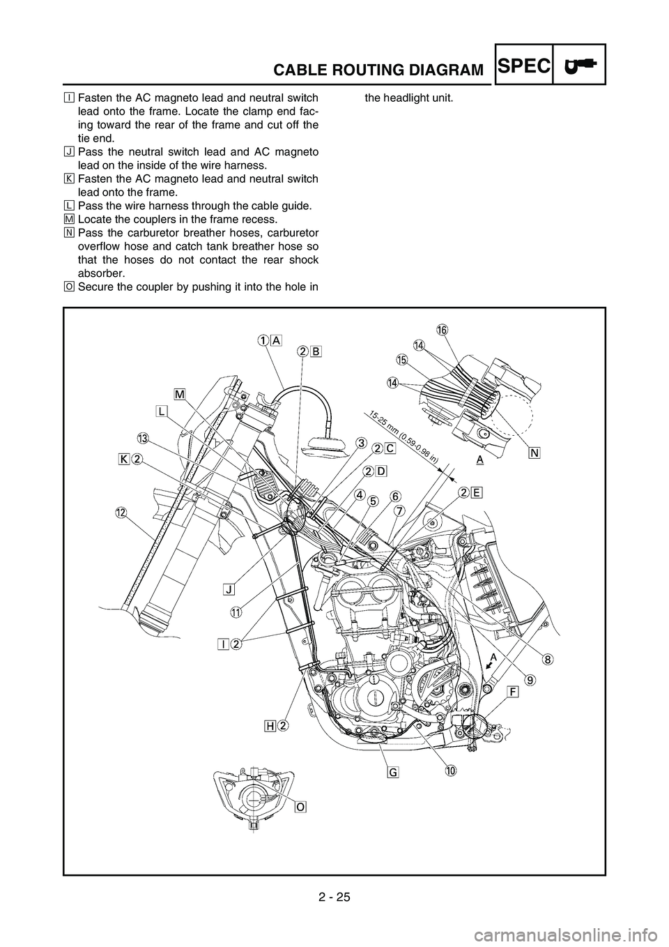
ÐFasten the AC magneto lead and neutral switch
lead onto the frame. Locate the clamp end fac-
ing toward the rear of the frame and cut off the
tie end.
ÑPass the neutral switch lead and AC magneto
lead on the inside of the wire harness.
ÒFasten the AC magneto lead and neutral switch
lead onto the frame.
ÓPass the wire harness through the cable guide.
ÔLocate the couplers in the frame recess.
ÕPass the carburetor breather hoses, carburetor
overflow hose and catch tank breather hose so
that the hoses do not contact the rear shock
absorber.
ÖSecure the coupler by pushing it into the hole inthe headlight unit.
Page 179 of 794
2 - 25
SPEC
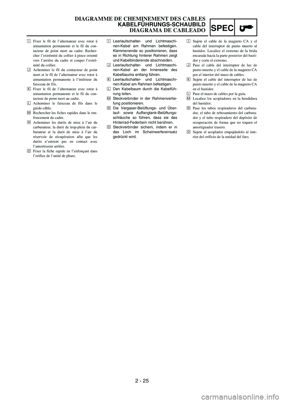
ÐLeerlaufschalter- und Lichtmaschi-
nen-Kabel am Rahmen befestigen.
Klemmenende so positionieren, dass
es in Richtung hinterer Rahmen zeigt
und Kabelbinderende abschneiden.
ÑLeerlaufschalter- und Lichtmaschi-
nen-Kabel an der Innenseite des
Kabelbaums entlang führen.
ÒLeerlaufschalter- und Lichtmaschi-
nen-Kabel am Rahmen befestigen.
ÓDen Kabelbaum durch die Kabelfüh-
rung leiten.
ÔSteckverbinder in der Rahmenvertie-
fung positionieren.
ÕDie Vergaser-Belüftungs- und Über-
lauf- sowie Auffangtank-Belüftungs-
schläuche so führen, dass sie das
Hinterrad-Federbein nicht berühren.
ÖSteckverbinder sichern, indem er in
das Loch im Scheinwerfereinsatz
gedrückt wird. ÐFixer le fil de l’alternateur avec rotor à
aimantation permanente et le fil du con-
tacteur de point mort au cadre. Recher-
cher l’extrémité du collier à pince orienté
vers l’arrière du cadre et couper l’extré-
mité du collier.
ÑAcheminer le fil du contacteur de point
mort et le fil de l’alternateur avec rotor à
aimantation permanente à l’intérieur du
faisceau de fils.
ÒFixer le fil de l’alternateur avec rotor à
aimantation permanente et le fil du con-
tacteur de point mort au cadre.
ÓAcheminer le faisceau de fils dans le
guide-câble.
ÔRechercher les fiches rapides dans le ren-
foncement du cadre.
ÕAcheminer les durits de mise à l’air du
carburateur, la durit de trop-plein du car-
burateur et la durit de mise à l’air du
réservoir de récupération afin que les
durits n’entrent pas en contact avec
l’amortisseur arrière.
ÖFixer la fiche rapide en l’enfonçant dans
l’orifice de l’unité de phare.ÐSujete el cable de la magneto CA y el
cable del interruptor de punto muerto al
bastidor. Localice el extremo de la brida
encarada hacia la parte posterior del basti-
dor y corte el extremo.
ÑPase el cable del interruptor de luz de
punto muerto y el cable de la magneto CA
por el interior del mazo de cables.
ÒSujete el cable del interruptor de luz de
punto muerto y el cable de la magneto CA
en el bastidor.
ÓPase el mazo de cables por la guía.
ÔLocalice los acopladores en la hendidura
del bastidor.
ÕPase los tubos respiraderos del carbura-
dor, el tubo de rebosamiento del carbura-
dor y el tubo respiradero del depósito de
recuperación de forma que no toquen el
amortiguador trasero.
ÖSujete el acoplador empujándolo al inte-
rior del orificio de la unidad del faro.
DIAGRAMME DE CHEMINEMENT DES CABLES
KABELFÜHRUNGS-SCHAUBILD
DIAGRAMA DE CABLEADO
Page 180 of 794
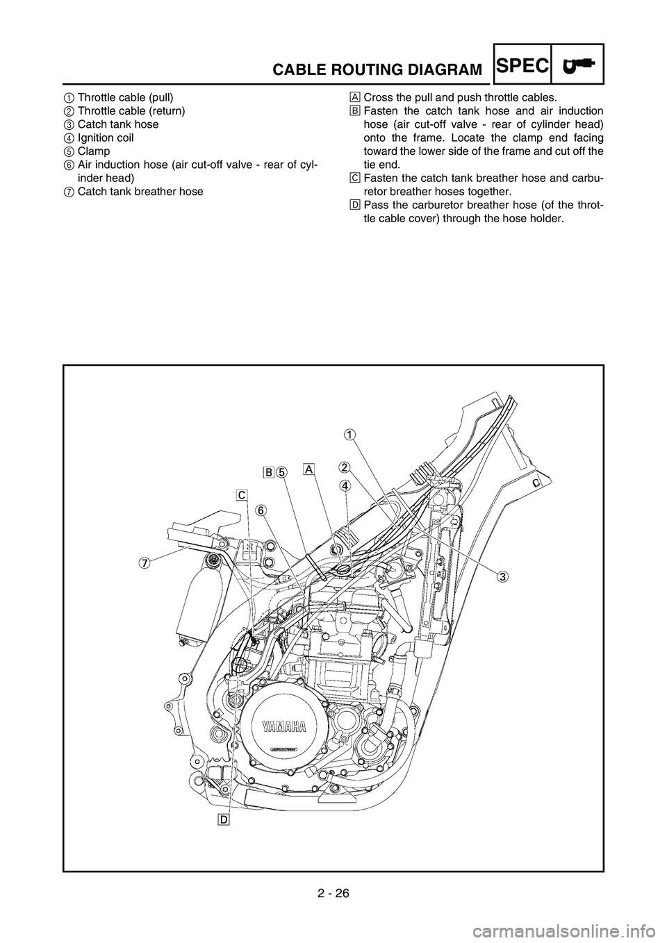
2 - 26
SPECCABLE ROUTING DIAGRAM
1Throttle cable (pull)
2Throttle cable (return)
3Catch tank hose
4Ignition coil
5Clamp
6Air induction hose (air cut-off valve - rear of cyl-
inder head)
7Catch tank breather hoseÈCross the pull and push throttle cables.
ÉFasten the catch tank hose and air induction
hose (air cut-off valve - rear of cylinder head)
onto the frame. Locate the clamp end facing
toward the lower side of the frame and cut off the
tie end.
ÊFasten the catch tank breather hose and carbu-
retor breather hoses together.
ËPass the carburetor breather hose (of the throt-
tle cable cover) through the hose holder.