YAMAHA WR 450F 2007 Betriebsanleitungen (in German)
Manufacturer: YAMAHA, Model Year: 2007, Model line: WR 450F, Model: YAMAHA WR 450F 2007Pages: 794, PDF-Größe: 21.82 MB
Page 181 of 794
2 - 26
SPEC
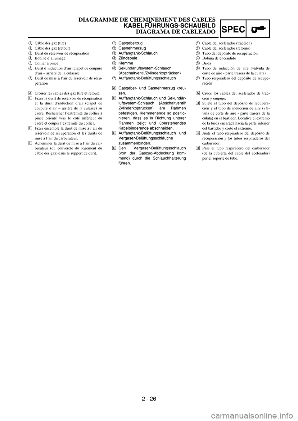
1Gasgeberzug
2Gasnehmerzug
3Auffangtank-Schlauch
4Zündspule
5Klemme
6Sekundärluftsystem-Schlauch
(Abschaltventil/Zylinderkopfrücken)
7Auffangtank-Belüftungsschlauch
ÈGasgeber- und Gasnehmerzug kreu-
zen.
ÉAuffangtank-Schlauch und Sekundär-
luftsystem-Schlauch (Abschaltventil/
Zylinderkopfrücken) am Rahmen
befestigen. Klemmenende so positio-
nieren, dass es in Richtung unterer
Rahmen zeigt und überstehendes
Kabelbinderende abschneiden.
ÊAuffangtank-Belüftungsschlauch und
Vergaser-Belüftungsschläuche
zusammenbinden.
ËDen Vergaser-Belüftungsschlauch
(von der Gaszug-Abdeckung kom-
mend) durch die Schlauchhalterung
führen. 1Câble des gaz (tiré)
2Câble des gaz (retour)
3Durit du réservoir de récupération
4Bobine d’allumage
5Collier à pince
6Durit d’induction d’air (clapet de coupure
d’air – arrière de la culasse)
7Durit de mise à l’air du réservoir de récu-
pération
ÈCroiser les câbles des gaz (tiré et retour).
ÉFixer la durit de réservoir de récupération
et la durit d’induction d’air (clapet de
coupure d’air – arrière de la culasse) au
cadre. Rechercher l’extrémité du collier à
pince orienté vers le côté inférieur du
cadre et couper l’extrémité du collier.
ÊFixer ensemble la durit de mise à l’air du
réservoir de récupération et les durits de
mise à l’air du carburateur.
ËAcheminer la durit de mise à l’air du car-
burateur (du couvercle du logement du
câble des gaz) dans le support de durit.1Cable del acelerador (tracción)
2Cable del acelerador (retorno)
3Tubo del depósito de recuperación
4Bobina de encendido
5Brida
6Tubo de inducción de aire (válvula de
corte de aire - parte trasera de la culata)
7Tubo respiradero del depósito de recupe-
ración
ÈCruce los cables del acelerador de trac-
ción y empuje.
ÉSujete el tubo del depósito de recupera-
ción y el tubo de inducción de aire (vál-
vula de corte de aire - parte trasera de la
culata) en el bastidor. Localice el extremo
de la brida encarada hacia la parte inferior
del bastidor y corte el extremo.
ÊJunte el tubo respiradero del depósito de
recuperación y los tubos respiraderos del
carburador.
ËPase el tubo respiradero del carburador
(de la cubierta del cable del acelerador)
por el soporte de tubo.
DIAGRAMME DE CHEMINEMENT DES CABLES
KABELFÜHRUNGS-SCHAUBILD
DIAGRAMA DE CABLEADO
Page 182 of 794
2 - 27
SPECCABLE ROUTING DIAGRAM
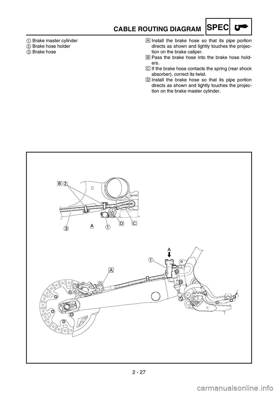
1Brake master cylinder
2Brake hose holder
3Brake hoseÈInstall the brake hose so that its pipe portion
directs as shown and lightly touches the projec-
tion on the brake caliper.
ÉPass the brake hose into the brake hose hold-
ers.
ÊIf the brake hose contacts the spring (rear shock
absorber), correct its twist.
ËInstall the brake hose so that its pipe portion
directs as shown and lightly touches the projec-
tion on the brake master cylinder.
Page 183 of 794
2 - 27
SPEC
1Hauptbremszylinder
2Bremsschlauch-Halterung
3Bremsschlauch
ÈDen Bremsschlauch so montieren,
dass der Metallstutzen am Schlau-
chende, wie abgebildet, an der Nase
des Bremssattels anliegt.
ÉDen Bremsschlauch durch die ent-
sprechenden Schlauchhalterungen
führen.
ÊFalls der Bremsschlauch die Feder
des Federbeins berührt, den
Schlauch entsprechend umbiegen.
ËDen Bremsschlauch so montieren,
dass der Metallstutzen am Schlau-
chende, wie abgebildet, an der Nase
des Bremssattels anliegt. 1Maître-cylindre de frein
2Support de durit de frein
3Durit de frein
ÈMonter la durit de frein de manière que sa
partie tubulaire soit orientée comme sur
l’illustration et touche légèrement la
saillie de l’étrier de frein.
ÉAcheminer la durit de frein dans les sup-
ports de durit de frein.
ÊSi la durit de frein entre en contact avec le
ressort (amortisseur arrière), en corriger la
torsion.
ËMonter la durit de frein de manière que sa
partie tubulaire soit orientée comme sur
l’illustration et touche légèrement la
saillie du maître-cylindre de frein.1Bomba de freno
2Soporte del tubo de freno
3Tubo de freno
ÈInstale el tubo de freno de forma que su
parte de tubería se sitúe como se muestra
y toque ligeramente la prolongación de la
pinza de freno.
ÉPase el tubo de freno por los soportes del
tubo de freno.
ÊSi el tubo de freno toca el muelle (amorti-
guador trasero), corrija su desviación.
ËInstale el tubo de freno de forma que su
parte de tubería se sitúe como se muestra
y toque ligeramente la prolongación de la
bomba de freno.
DIAGRAMME DE CHEMINEMENT DES CABLES
KABELFÜHRUNGS-SCHAUBILD
DIAGRAMA DE CABLEADO
Page 184 of 794

2 - 28
SPECCABLE ROUTING DIAGRAM
1Clamp
2Positive battery lead
3Battery
4Negative battery lead
5Taillight coupler
6CDI unit coupler (6-pin)
7CDI unit coupler (3-pin)
8CDI unit coupler (6-pin)ÈFasten the wire harness to the upper engine
bracket (left side). Locate the clamp end facing
toward the upper side of the frame with the tie
end cut off on the inside of the frame.
ÉFasten the wire harness to the upper engine
bracket (left side). Locate the clamp end facing
toward the upper side of the frame with the tie
end cut off on the inside of the frame. Clamp the
wire harness at the marking.
ÊPass the starter motor lead through the hole in
the relay holder.
ËFit the cover securely.
ÌConnect the wire harness to the starter relay.
Page 185 of 794
2 - 28
SPEC
1Klemme
2Batterie-Pluskabel
3Batterie
4Batterie-Minuskabel
5Rücklicht-Steckverbinder
6CDI-Zündbox-Steckverbinder
(6-polig)
7CDI-Zündbox-Steckverbinder
(3-polig)
8CDI-Zündbox-Steckverbinder
(6-polig)
ÈKabelbaum an der oberen Motorhalte-
rung (linksseitig) befestigen. Klemme-
nende so positionieren, dass es in
Richtung der Oberseite des Rahmens
zeigt und das Kabelbinderende auf
der Rahmeninnenseite abgeschnitten
ist.
ÉKabelbaum an der oberen Motorhalte-
rung (linksseitig) befestigen. Klemme-
nende so positionieren, dass es in
Richtung der Oberseite des Rahmens
zeigt und das Kabelbinderende auf
der Rahmeninnenseite abgeschnitten
ist. Den Kabelbaum an der Markie-
rung mit einer Klemme befestigen.
ÊStarter-Kabel durch das Loch im
Relais-Halter führen.
ËAbdeckung so anbringen, dass sie
fest sitzt.
ÌKabelbaum an Starter-Relais
anschließen. 1Collier à pince
2Câble positif de batterie
3Batterie
4Câble négatif de batterie
5Fiche rapide du feu arrière
6Fiche rapide du boîtier CDI (6 broches)
7Fiche rapide du boîtier CDI (3 broches)
8Fiche rapide du boîtier CDI (6 broches)
ÈFixer le faisceau de fils au support de
moteur supérieur (côté gauche). Recher-
cher l’extrémité du collier à pince orienté
vers le côté supérieur du cadre en coupant
l’extrémité du collier à l’intérieur du
cadre.
ÉFixer le faisceau de fils au support de
moteur supérieur (côté gauche). Recher-
cher l’extrémité du collier à pince orienté
vers le côté supérieur du cadre en coupant
l’extrémité du collier à l’intérieur du
cadre. Brider le faisceau de fils au repère.
ÊAcheminer le fil du démarreur dans l’ori-
fice du support de relais.
ËFixer solidement le couvercle.
ÌBrancher le faisceau de fils au relais de
démarreur.1Brida
2Cable positivo de la batería
3Batería
4Cable negativo de la batería
5Acoplador del piloto trasero
6Acoplador de la unidad CDI (6 patillas)
7Acoplador de la unidad CDI (3 patillas)
8Acoplador de la unidad CDI (6 patillas)
ÈSujete el mazo de cables al soporte supe-
rior del motor (lado izquierdo). Localice
el extremo de la brida encarada hacia la
parte superior del bastidor con el extremo
cortado en el interior del mismo.
ÉSujete el mazo de cables al soporte supe-
rior del motor (lado izquierdo). Localice
el extremo de la brida encarada hacia la
parte superior del bastidor con el extremo
cortado en el interior del mismo. Sujete el
mazo de cables por la marca.
ÊPase el cable del motor de arranque por el
orificio del soporte del relé.
ËEncaje la cubierta correctamente.
ÌConecte el mazo de cables al relé de
arranque.
DIAGRAMME DE CHEMINEMENT DES CABLES
KABELFÜHRUNGS-SCHAUBILD
DIAGRAMA DE CABLEADO
Page 186 of 794

2 - 29
SPECCABLE ROUTING DIAGRAM
ÍFasten the catch tank breather
hose and catch tank hose to the
rear frame. Clamp them close
to where they are joined to the
frame. Fasten the pipe tightly
enough not to crush it. Locate
the clamp end facing toward the
rear of the frame with the tie
end facing downward.
ÎFasten the (three) CDI unit
leads and taillight lead to the
rear frame. Locate the clamp
end facing toward the upper
side of the frame and cut off the
tie end.
ÏConnect the negative battery
lead to the battery negative ter-
minal.
ÐConnect the negative battery
lead to the wire harness.ÑFasten the wire harness to the
rear frame. Locate the clamp
end facing toward the upper
side of the frame and the tie
end toward the inside of the
frame. Clamp the wire harness
at the marking.
ÒPass the wire harness, starter
relay lead, starting circuit cut-off
relay lead and negative battery
lead through the hole in the
relay holder.
ÓFasten the (three) CDI unit
leads and taillight lead to the
rear frame. Locate the clamp
end facing toward the lower
side of the frame and cut off the
tie end.ÔFasten the taillight lead to the
rear frame. Locate the clamp
end facing toward the upper
side of the frame and cut off the
tie end.
ÕDo not allow the taillight lead to
slacken.
ÖLocate the CDI unit lead
between the CDI unit and rear
fender.
×Locate the CDI unit coupler in
the clearance between the
upper side of the CDI unit and
lower side of the catch tank
stay.
ØLocate the CDI unit lead
between the CDI unit and rear
frame.
Page 187 of 794
2 - 29
SPEC
ÍAuffangtank-Belüftungsschlauch und
Auffangtank-Schlauch am hinteren
Teil des Rahmens anbringen. Mit
einer Klemme nahe der Stelle befesti-
gen, wo sie in den Rahmen eintreten.
Die Leitung so fest anbringen, dass
sie nicht gequetscht wird. Klemme-
nende so positionieren, dass es in
Richtung hinterer Rahmen zeigt und
das Kabelbinderende nach unten
zeigt.
ÎDie (drei) Kabel der CDI-Zündbox und
das Rücklicht-Kabel am hinteren Rah-
men befestigen. Klemmenende so
positionieren, dass es in Richtung der
Oberseite des Rahmens zeigt und
Kabelbinderende abschneiden.
ÏBatterie-Minuskabel an Batterie-
Minuspol anschließen.
ÐBatterie-Minuskabel an Kabelbaum
anschließen.
ÑKabelbaum am hinteren Teil des Rah-
mens befestigen. Klemmenende so
positionieren, dass es in Richtung der
Oberseite des Rahmens zeigt und
das Kabelbinderende in Richtung
Rahmeninnenseite zeigt. Den Kabel-
baum an der Markierung mit einer
Klemme befestigen.
ÒKabelbaum, Starter-Relais-Kabel,
Anlasssperrelais-Kabel und Batterie-
Minuskabel durch das Loch im Relais-
Halter führen.
ÓDie (drei) Kabel der CDI-Zündbox und
das Rücklicht-Kabel am hinteren Rah-
men befestigen. Klemmenende so
positionieren, dass es in Richtung
unterer Rahmen zeigt und überste-
hendes Kabelbinderende abschnei-
den.
ÔRücklicht-Kabel am hinteren Teil des
Rahmens befestigen. Klemmenende
so positionieren, dass es in Richtung
der Oberseite des Rahmens zeigt und
Kabelbinderende abschneiden.
ÕDas Rücklicht-Kabel muss straff sein.
ÖCDI-Zündbox-Kabel zwischen CDI-
Zündbox und Hinterradabdeckung
führen.
×CDI-Zündbox-Steckverbinder in das
Spiel zwischen der Oberseite der
CDI-Zündbox und der Unterseite der
Auffangtank-Halterung positionieren.
ØCDI-Zündbox-Kabel zwischen CDI-
Zündbox und hinterem Rahmen füh-
ren. ÍFixer la durit de mise à l’air du réservoir
de récupération et la durit du réservoir de
récupération au cadre arrière. Les brider à
proximité de leur point de jonction sur le
cadre. Fixer fermement le tuyau pour évi-
ter qu’il ne soit écrasé. Rechercher
l’extrémité du collier à pince orienté vers
l’arrière du cadre en plaçant l’extrémité
du collier vers le bas.
ÎFixer les (trois) câbles du boîtier CDI et le
fil du feu arrière au cadre arrière. Recher-
cher l’extrémité du collier à pince orienté
vers le côté supérieur du cadre et couper
l’extrémité du collier.
ÏBrancher le câble négatif de batterie à la
borne négative de la batterie.
ÐBrancher le câble négatif de batterie au
faisceau de fils.
ÑFixer le faisceau de fils au cadre arrière.
Rechercher l’extrémité du collier à pince
orienté vers le côté supérieur du cadre et
l’extrémité du collier à l’intérieur du
cadre. Brider le faisceau de fils au repère.
ÒAcheminer le faisceau de fils, le fil du
relais de démarreur, le fil de relais de
coupe-circuit de démarrage et le câble
négatif de batterie dans l’orifice du sup-
port de relais.
ÓFixer les (trois) fils du boîtier CDI et le fil
du feu arrière au cadre arrière. Rechercher
l’extrémité du collier à pince orienté vers
le côté inférieur du cadre et couper
l’extrémité du collier.
ÔFixer le fil du feu arrière au cadre arrière.
Rechercher l’extrémité du collier à pince
orienté vers le côté supérieur du cadre et
couper l’extrémité du collier.
ÕNe pas laisser de mou au fil du feu arrière.
ÖRechercher le fil du boîtier CDI entre le
boîtier CDI et le garde-boue arrière.
×Rechercher la fiche rapide du boîtier CDI
dans l’espace entre le côté supérieur du
boîtier CDI et le côté inférieur du support
de réservoir de récupération.
ØRechercher le fil du boîtier CDI entre le
boîtier CDI et le cadre arrière.ÍSujete el tubo respiradero del depósito de
recuperación y el tubo del depósito de
recuperación al bastidor posterior. Sujéte-
los cerca de su punto de unión al bastidor.
Sujete la tubería con la suficiente firmeza
para no aplastarla. Localice el extremo de
la brida encarada hacia la parte posterior
del bastidor con el extremo encarado
hacia abajo.
ÎSujete los (tres) cables de la unidad CDI y
el cable del piloto trasero al bastidor pos-
terior. Localice el extremo de la brida
encarada hacia la parte superior del basti-
dor y corte el extremo.
ÏConecte el cable negativo de la batería al
terminal negativo de la batería.
ÐConecte el cable negativo de la batería al
mazo de cables.
ÑSujete el mazo de cables al bastidor poste-
rior. Localice el extremo de la brida enca-
rada hacia la parte superior del bastidor y
el extremo hacia el interior del mismo.
Sujete el mazo de cables por la marca.
ÒPase el mazo de cables, el cable del relé
de arranque, el cable del relé de corte del
circuito de arranque y el cable negativo de
la batería por el orificio del soporte del
relé.
ÓSujete los (tres) cables de la unidad CDI y
el cable del piloto trasero al bastidor pos-
terior. Localice el extremo de la brida
encarada hacia la parte inferior del basti-
dor y corte el extremo.
ÔSujete el cable del piloto trasero al basti-
dor posterior. Localice el extremo de la
brida encarada hacia la parte superior del
bastidor y corte el extremo.
ÕNo deje que se afloje el cable del piloto
trasero.
ÖLocalice el cable de la unidad CDI
situado entre la unidad CDI y el guarda-
barros posterior.
×Localice el acoplador de la unidad CDI en
la holgura situada entre la parte superior
de la unidad CDI y la parte inferior del
apoyo del depósito de recuperación.
ØLocalice el cable de la unidad CDI
situado entre la unidad CDI y el bastidor
posterior.
DIAGRAMME DE CHEMINEMENT DES CABLES
KABELFÜHRUNGS-SCHAUBILD
DIAGRAMA DE CABLEADO
Page 188 of 794
2 - 30
SPECCABLE ROUTING DIAGRAM
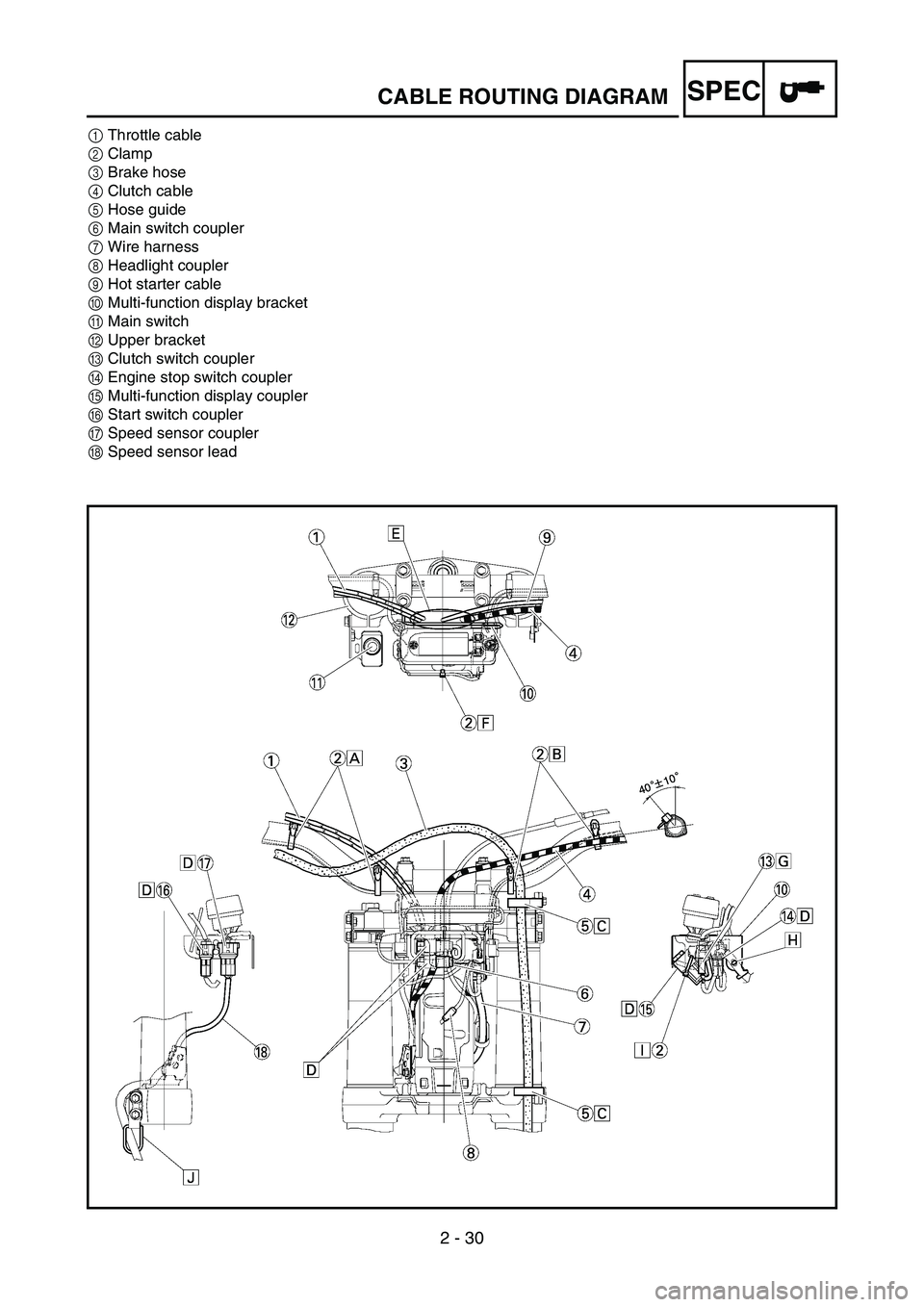
1Throttle cable
2Clamp
3Brake hose
4Clutch cable
5Hose guide
6Main switch coupler
7Wire harness
8Headlight coupler
9Hot starter cable
0Multi-function display bracket
AMain switch
BUpper bracket
CClutch switch coupler
DEngine stop switch coupler
EMulti-function display coupler
FStart switch coupler
GSpeed sensor coupler
HSpeed sensor lead
Page 189 of 794

2 - 30
SPEC
1Gaszug
2Klemme
3Bremsschlauch
4Kupplungszug
5Schlauchführung
6Zündschloss-Steckverbinder
7Kabelbaum
8Scheinwerfer-Steckverbinder
9Warmstartzug
0Multifunktionsanzeigen-Halterung
AZündschloss
BObere Gabelbrücke
CKupplungsschalter-Steckverbinder
DMotorstoppschalter-Steckverbinder
EMultifunktionsanzeigen-Steckverbin-
der
FStarterschalter-Steckverbinder
GGeschwindigkeitssensor-Steckverbin-
der
HGeschwindigkeitssensor-Kabel 1Câble des gaz
2Collier à pince
3Durit de frein
4Câble d’embrayage
5Guide de durit
6Fiche rapide du contacteur à clé
7Faisceau de fils
8Fiche rapide du phare
9Câble de starter à chaud
0Support de l’écran multifonction
AContacteur à clé
BTé supérieur
CFiche rapide du contacteur d’embrayage
DFiche rapide du coupe-circuit du moteur
EFiche rapide de l’écran multifonction
FFiche rapide du contacteur de démarrage
GFiche rapide du capteur de vitesse
HFil du capteur de vitesse1Cable del acelerador
2Brida
3Tubo de freno
4Cable de embrague
5Guía de tubo
6Acoplador del interruptor principal
7Mazo de cables
8Acoplador del faro
9Cable de arranque en caliente
0Soporte del visor multifunción
AInterruptor principal
BSoporte superior
CAcoplador del interruptor del embrague
DAcoplador del interruptor de paro del
motor
EAcoplador del visor multifunción
FAcoplador del interruptor de arranque
GAcoplador del sensor de velocidad
HCable del sensor de velocidad
DIAGRAMME DE CHEMINEMENT DES CABLES
KABELFÜHRUNGS-SCHAUBILD
DIAGRAMA DE CABLEADO
Page 190 of 794

2 - 31
SPECCABLE ROUTING DIAGRAM
ÈFasten the start switch lead to the handlebar
with the plastic bands.
ÉFasten the engine stop switch lead and clutch
switch lead to the handlebar with the plastic
bands.
ÊPass the brake hose through the hose guides.
ËSecure the coupler by inserting it into the multi-
function display bracket.
ÌPass the throttle cables, clutch cable and hot
starter cable between the upper bracket and
multi-function display bracket.
ÍFasten the multi-function display leads to the
bracket. Cut off the tie end.
ÎSecure the coupler by pushing it into the hole in
the multi-function display bracket.
ÏSecure the wire harness clip by pushing it into
the hole in the multi-function display bracket on
the inside.ÐFasten the main switch lead (wire harness side)
to the multi-function display bracket. Locate the
clamp end facing toward the lower side of the
frame and cut off the tie end.
ÑPass the speed sensor lead through the guide
on the outside of the front fork.