YAMAHA WR 450F 2007 Notices Demploi (in French)
Manufacturer: YAMAHA, Model Year: 2007, Model line: WR 450F, Model: YAMAHA WR 450F 2007Pages: 794, PDF Size: 21.82 MB
Page 731 of 794
–+ELEC
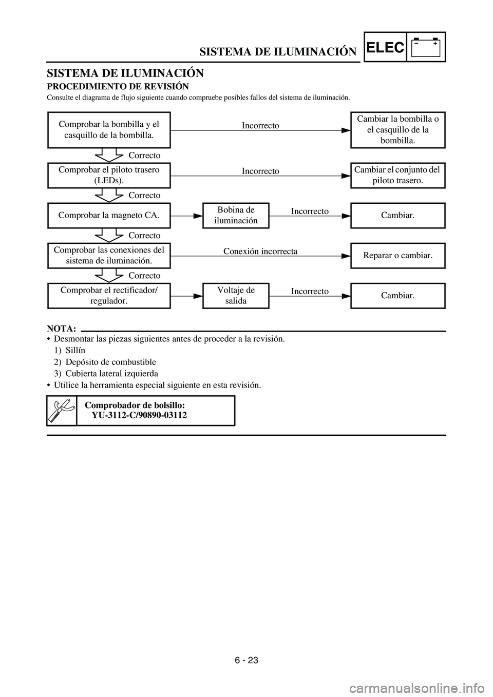
SISTEMA DE ILUMINACIÓN
PROCEDIMIENTO DE REVISIÓN
Consulte el diagrama de flujo siguiente cuando compruebe posibles fallos del sistema de iluminación.
NOTA:
Desmontar las piezas siguientes antes de proceder a la revisión.
1) Sillín
2) Depósito de combustible
3) Cubierta lateral izquierda
Utilice la herramienta especial siguiente en esta revisión.
Comprobar la bombilla y el
casquillo de la bombilla.Cambiar la bombilla o
el casquillo de la
bombilla.
Comprobar el piloto trasero
(LEDs).Cambiar el conjunto del
piloto trasero.
Comprobar la magneto CA.Bobina de
iluminaciónCambiar.
Comprobar las conexiones del
sistema de iluminación.Reparar o cambiar.
Comprobar el rectificador/
regulador.Voltaje de
salidaCambiar.
Comprobador de bolsillo:
YU-3112-C/90890-03112
Incorrecto
Correcto
Incorrecto
Correcto
Incorrecto
Correcto
Conexión incorrecta
Correcto
Incorrecto
SISTEMA DE ILUMINACIÓN
6 - 23
Page 732 of 794
6 - 24
–+ELECLIGHTING SYSTEM
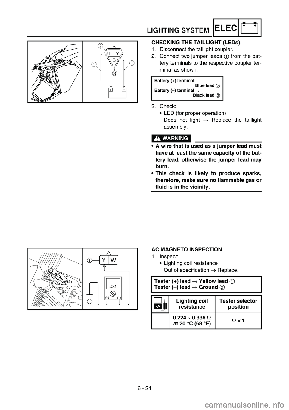
CHECKING THE TAILLIGHT (LEDs)
1. Disconnect the taillight coupler.
2. Connect two jumper leads 1 from the bat-
tery terminals to the respective coupler ter-
minal as shown.
3. Check:
•LED (for proper operation)
Does not light → Replace the taillight
assembly.
WARNING
A wire that is used as a jumper lead must
have at least the same capacity of the bat-
tery lead, otherwise the jumper lead may
burn.
This check is likely to produce sparks,
therefore, make sure no flammable gas or
fluid is in the vicinity.
Battery (+) terminal →
Blue lead
2
Battery (–) terminal →
Black lead
3
AC MAGNETO INSPECTION
1. Inspect:
•Lighting coil resistance
Out of specification → Replace.
Tester (+) lead
→ Yellow lead
1
Tester (–) lead
→ Ground
2
Lighting coil
resistanceTester selector
position
0.224 ~ 0.336
Ω
at 20 °C (68 °F)Ω
× 1
Page 733 of 794
–+ELEC
RÜCKLICHT (LEDs)
KONTROLLIEREN
1. Den Rücklicht-Steckverbinder
abziehen.
2. Batteriepole mit den entspre-
chenden Steckverbinder-
Anschlüssen durch zwei Über-
brückungskabel 1 wie gezeigt
verbinden.
3. Kontrollieren:
LED (auf einwandfreie Funk-
tion)
Leuchtet nicht → Rücklicht-
Baugruppe ersetzen.
WARNUNG
Der Querschnitt des Überbrü-
ckungskabels muss mindes-
tens so groß wie der des
Batteriekabels sein; anderen-
falls besteht Brandgefahr.
Wegen möglicher Funkenbil-
dung darf diese Kontrolle nicht
in der Nähe von entzündlichen
Gasen oder Flüssigkeiten erfol-
gen. Batterie (+) Pluspol →
Blaues Kabel 2
Batterie (–) Minuspol →
Schwarzes Kabel 3
LICHTMASCHINE
KONTROLLIEREN
1. Kontrollieren:
Lichtspulen-Widerstand
Nicht nach Vorgabe → Erneu-
ern.
Messkabel (+) → Gelb 1
Messkabel (–) → Masse 2
Lichtspulen-
WiderstandMessgerät-
Wahlschalter
0,224–
0,336 Ω bei
20 °C (68 °F)Ω × 1
CONTROLE DU FEU ARRIERE
(DEL)
1. Débrancher la fiche rapide du feu
arrière.
2. Brancher deux cavaliers 1 des bor-
nes de la batterie aux bornes corres-
pondantes de la fiche rapide,
comme illustré.
3. Contrôler:
LED (pour un bon fonctionne-
ment)
Ne s’allume pas → Remplacer le
feu arrière complet.
AVERTISSEMENT
Un cavalier doit avoir au moins la
même capacité qu’un câble de bat-
terie sinon il risque de brûler.
Ce contrôle est susceptible de pro-
duire des étincelles. Il convient donc
d’éloigner tout gaz ou liquide
inflammable. Borne (+) de la batterie →
Fil bleu 2
Borne (–) de la batterie →
Fil noir 3
CONTROLE DE L’ALTERNATEUR
AVEC ROTOR A AIMENTATION
PERMANENTE
1. Contrôler:
Résistance de la bobine d’éclai-
rage
Hors spécifications → Rempla-
cer.
Fil (+) du multimètre → fil jaune 1
Fil (–) du multimètre → terre 2
Résistance de
la bobine
d’éclairagePosition du
sélecteur du
multimètre
0,224 à
0,336 Ω à
20 °C (68 °F)Ω × 1
COMPROBAR EL PILOTO
TRASERO (LEDs)
1. Desconecte el acoplador del piloto
trasero.
2. Conecte dos puentes 1 desde los
terminales de la batería al terminal
del acoplador respectivo, como se
muestra.
3. Comprobar:
LED (que funcione correcta-
mente)
No se ilumina → Cambiar el con-
junto del piloto trasero.
ADVERTENCIA
El cable que se utilice como puente
debe tener como mínimo la misma
capacidad que el cable de la batería;
de lo contrario, el puente se puede
quemar.
Durante esta prueba es probable
que se produzcan chispas; por lo
tanto, compruebe que no haya gases
ni líquidos inflamables en las proxi-
midades. Terminal (+) de la batería →
Cable azul 2
Terminal (–) de la batería →
Cable negro 3
COMPROBACIÓN DE LA
MAGNETO CA
1. Comprobar:
Resistencia de la bobina de luz
Fuera del valor especificado →
Cambiar.
Cable (+) del comprobador →
Cable amarillo 1
Cable (–) del comprobador →
Masa 2
Resistencia de
la bobina de
luzPosición del
selector del
comprobador
0,224 ~
0,336 Ω a
20 °C (68 °F)Ω × 1
ECLAIRAGE
BELEUCHTUNGSANLAGE
SISTEMA DE ILUMINACIÓN
6 - 24
Page 734 of 794
6 - 25
–+ELEC
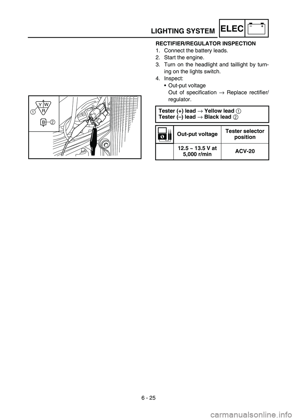
RECTIFIER/REGULATOR INSPECTION
1. Connect the battery leads.
2. Start the engine.
3. Turn on the headlight and taillight by turn-
ing on the lights switch.
4. Inspect:
•Out-put voltage
Out of specification → Replace rectifier/
regulator.
Tester (+) lead → Yellow lead 1
Tester (–) lead → Black lead 2
Out-put voltageTester selector
position
12.5 ~ 13.5 V at
5,000 r/minACV-20
R
BW
Y1
2
LIGHTING SYSTEM
Page 735 of 794
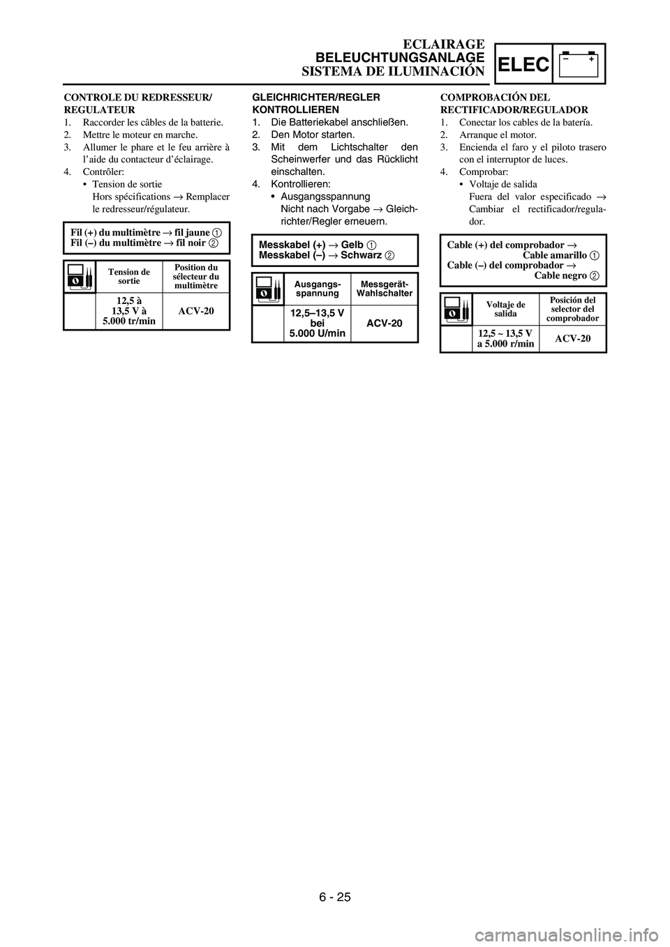
–+ELEC
GLEICHRICHTER/REGLER
KONTROLLIEREN
1. Die Batteriekabel anschließen.
2. Den Motor starten.
3. Mit dem Lichtschalter den
Scheinwerfer und das Rücklicht
einschalten.
4. Kontrollieren:
Ausgangsspannung
Nicht nach Vorgabe → Gleich-
richter/Regler erneuern.
Messkabel (+) → Gelb 1
Messkabel (–) → Schwarz 2
Ausgangs-
spannungMessgerät-
Wahlschalter
12,5–13,5 V
bei
5.000 U/minACV-20
CONTROLE DU REDRESSEUR/
REGULATEUR
1. Raccorder les câbles de la batterie.
2. Mettre le moteur en marche.
3. Allumer le phare et le feu arrière à
l’aide du contacteur d’éclairage.
4. Contrôler:
Tension de sortie
Hors spécifications → Remplacer
le redresseur/régulateur.
Fil (+) du multimètre → fil jaune 1
Fil (–) du multimètre → fil noir 2
Tension de
sortiePosition du
sélecteur du
multimètre
12,5 à
13,5 V à
5.000 tr/minACV-20
COMPROBACIÓN DEL
RECTIFICADOR/REGULADOR
1. Conectar los cables de la batería.
2. Arranque el motor.
3. Encienda el faro y el piloto trasero
con el interruptor de luces.
4. Comprobar:
Voltaje de salida
Fuera del valor especificado →
Cambiar el rectificador/regula-
dor.
Cable (+) del comprobador →
Cable amarillo 1
Cable (–) del comprobador →
Cable negro 2
Voltaje de
salidaPosición del
selector del
comprobador
12,5 ~ 13,5 V
a 5.000 r/minACV-20
ECLAIRAGE
BELEUCHTUNGSANLAGE
SISTEMA DE ILUMINACIÓN
6 - 25
Page 736 of 794

–+ELEC
6 - 26
SIGNALING SYSTEM
SIGNALING SYSTEM
INSPECTION STEPS
If the speedometer will not operate, use the following inspection steps.
*1 marked: Refer to “BATTERY INSPECTION AND CHARGING” section in the CHAPTER 3.
NOTE:
•Remove the following parts before inspection.
1) Headlight
•Use the following special tools in this inspection.
Pocket tester:
YU-3112-C/90890-03112
*1 Check battery. Recharge or replace.
Check each coupler and
wire connection.Repair or replace.
Check multi-function dis-
play.Input voltage Replace wire harness.
Output voltageReplace multi-func-
tion display.
Check speed sensor. Replace.
OK
OK
OK
No good
No good
No good No good
No good
Page 737 of 794
–+ELEC
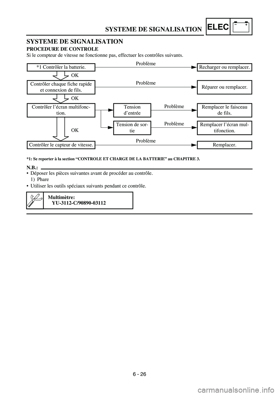
SYSTEME DE SIGNALISATION
PROCEDURE DE CONTROLE
Si le compteur de vitesse ne fonctionne pas, effectuer les contrôles suivants.
*1: Se reporter à la section “CONTROLE ET CHARGE DE LA BATTERIE” au CHAPITRE 3.
N.B.:
Déposer les pièces suivantes avant de procéder au contrôle.
1) Phare
Utiliser les outils spéciaux suivants pendant ce contrôle.
Multimètre:
YU-3112-C/90890-03112
*1 Contrôler la batterie. Recharger ou remplacer.
Contrôler chaque fiche rapide
et connexion de fils.Réparer ou remplacer.
Contrôler l’écran multifonc-
tion.Tension
d’entréeRemplacer le faisceau
de fils.
Tension de sor-
tieRemplacer l’écran mul-
tifonction.
Contrôler le capteur de vitesse. Remplacer.
OK
OK
OK
Problème
Problème
Problème Problème
Problème
SYSTEME DE SIGNALISATION
6 - 26
Page 738 of 794

–+ELEC
SIGNALANLAGE
KONTROLLE
Folgende Prüfschritte dienen zur Diagnose des Geschwindigkeitssensors, wenn dieser nicht funkti-
oniert.
*1: Siehe unter “BATTERIE KONTROLLIEREN UND LADEN” in KAPITEL 3.
HINWEIS:
Vor der Kontrolle folgende Bauteile demontieren:
1) Scheinwerfer
Folgendes Spezialwerkzeug für die Kontrolle verwenden:
Taschen-Multimeter
YU-3112-C/90890-03112
*1 Batterie kontrollieren. Laden, ggf. erneuern.
Sämtliche Steckverbinder-
und Kabelanschlüsse kon-
trollieren.Instand setzen, ggf.
erneuern.
Multifunktionsanzeige kon-
trollierenEingangs-
spannungKabelbaum erneuern.
Ausgangs-
spannungMultifunktionsan-
zeige erneuern.
Geschwindigkeitssensor
kontrollieren.Erneuern.
In Ordnung
In Ordnung
In Ordnung
Nicht in Ordnung
Nicht in Ordnung Nicht in Ordnung
Nicht in Ordnung
Nicht in Ordnung
SIGNALANLAGE
6 - 26
Page 739 of 794

–+ELEC
SISTEMA DE SEÑALIZACIÓN
PROCEDIMIENTO DE REVISIÓN
Si el velocímetro no funciona utilice el procedimiento de comprobación siguiente.
*1 marcado: Consulte el apartado “COMPROBACIÓN Y CARGA DE LA BATERÍA” del CAPÍTULO 3.
NOTA:
Desmontar las piezas siguientes antes de proceder a la revisión.
1) Faro
Utilice las herramientas especiales siguientes en esta revisión.
Comprobador de bolsillo:
YU-3112-C/90890-03112
*1 Comprobar batería. Recargar o cambiar.
Comprobar todos los acopla-
dores y conexiones de cables.Reparar o cambiar.
Comprobar el visor multifun-
ción.Voltaje de
entradaCambiar el mazo de
cables.
Voltaje de
salidaCambiar el visor multi-
función.
Comprobar el sensor de velo-
cidad.Cambiar.
Correcto
Correcto
Correcto
Incorrecto
Incorrecto
Incorrecto Incorrecto
Incorrecto
SISTEMA DE SEÑALIZACIÓN
6 - 26
Page 740 of 794

6 - 27
–+ELECSIGNALING SYSTEM
COUPLERS AND LEADS CONNECTION
INSPECTION
1. Check:
•Couplers and leads connection
Rust/dust/looseness/short-circuit →
Repair or replace.
MULTI-FUNCTION DISPLAY INPUT
VOLTAGE INSPECTION
1. Disconnect the multi-function display cou-
pler.
2. Set the main switch to “ON”.
3. Measure:
•Multi-function display input voltage
Out of specification → Replace wire har-
ness.
CAUTION:
Make sure that a short-circuit does not
develop between the terminals because it
may cause damage to electrical compo-
nents.Tester (+) lead
→ Brown lead
1
Tester (–) lead
→ Black lead
2
Multi-function dis-
play input voltageTester selec-
tor position
10 V or more DCV-20
MULTI-FUNCTION DISPLAY OUTPUT
VOLTAGE INSPECTION
1. Disconnect the multi-function display cou-
pler.
2. Set the main switch to “ON”.