engine YAMAHA XT660Z 2010 User Guide
[x] Cancel search | Manufacturer: YAMAHA, Model Year: 2010, Model line: XT660Z, Model: YAMAHA XT660Z 2010Pages: 100, PDF Size: 6.91 MB
Page 22 of 100

INSTRUMENT AND CONTROL FUNCTIONS
4-6
1
2
3
4
5
6
7
8
9
10
Tachometer
1. Tachometer
2. Red zone
The tachometer allows the rider to
monitor the engine speed and keep it
within the ideal power range.
When the key is turned to "ON", the
tachometer needle will sweep once
across the r/min range and then return
to zero r/min in order to test the elec-
trical circuit.
ECA10030
NOTICE
Do not operate the engine in the
tachometer red zone.
Red zone: 7,500 r/min and above.
Tripmeter and tachometer modes
1. “SELECT” button
2. “RESET” button
Pushing the "SELECT" button switch-
es the display between the tripmeter
modes "TRIP 1" and "TRIP 2" in the
following order:
TRIP 1
6TRIP 2 6TRIP 1
When the fuel amount in the fuel tank
decreases to 6.7 L (1.77 US gal) (1.47
Imp.gal), the bottom segment of the
fuel meter will start flashing, and the
tripmeter display will automatically
change to the fuel reserve tripmeter
mode “F-TRIP” and start counting the
distance traveled from that point. In
that case, pushing the "SELECT" but-
ton switches the display between the
various tripmeter modes in the follow-
ing order:
F-TRIP
6TRIP 1 6TRIP 2 6F-TRIP
To reset a tripmeter, select it by push-
ing the "SELECT" button, and then
push the "RESET" button for at least
four seconds. If you do not reset the
fuel reserve tripmeter manually, it will
reset itself automatically and the dis-
play will return to the prior mode after
refueling and traveling 5 km (3 mi).
XT660Z 04-04 ING-AUS:MY03 01-03 ING 11-05-2009 9:54 Pagina 4-6
Page 24 of 100

INSTRUMENT AND CONTROL FUNCTIONS
4-8
1
2
3
4
5
6
7
8
9
10
Self-diagnosis devices
1. Engine trouble warning light “U”
2. Immobilizer system indicator light “ ”
This model is equipped with a self-di-
agnosis device for various electrical
circuits.
If any of those circuits are defective,
the engine trouble warning light will
start flashing. If this occurs, have a
Yamaha dealer check the vehicle.
This model is also equipped with a
self-diagnosis device for the immobi-
lizer system.
If any of the immobilizer system cir-
cuits are defective, the immobilizer
system indicator light will start flash-
ing.
If this occurs, have a Yamaha dealer
check the vehicle.
TIP
If the indicator light slowly flashes five
times, and then quickly flashes two
times repeatedly, this error could be
caused by transponder interference. If
this occurs, try the following.
1. Use the code re-registering key to
start the engine.
TIP
Make sure there are no other immobi-
lizer keys close to the main switch, and
do not keep more than one immobiliz-
er key on the same key ring! Immobi-
lizer system keys may cause signal in-
terference, which may prevent the
engine from starting.2. If the engine starts, turn it off, and
try starting the engine with the
standard keys.
3. If one or both of the standard keys
do not start the engine, take the
vehicle, the code re-registering
key and both standard keys to a
Yamaha dealer and have the
standard keys re-registered.
If the immobilizer system indicator
light continues to flash, have a Yama-
ha dealer check the vehicle.
XT660Z 04-04 ING-AUS:MY03 01-03 ING 11-05-2009 9:54 Pagina 4-8
Page 25 of 100

1
2
3
4
5
6
7
8
9
10
INSTRUMENT AND CONTROL FUNCTIONS
4-9
EAU12348
Handlebar switches
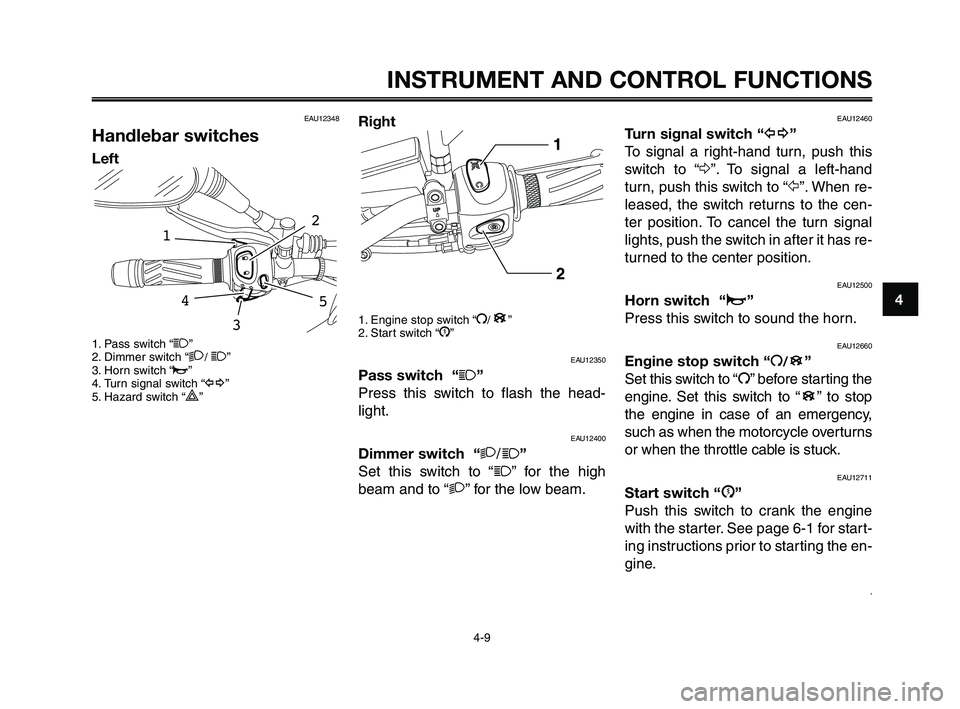
Left
1. Pass switch “1”
2. Dimmer switch “2/ 1”
3. Horn switch “o”
4. Turn signal switch “y”
5. Hazard switch “
r”
54
2
1
3
Right
1. Engine stop switch “I/”
2. Start switch “J”
EAU12350
Pass switch “1”
Press this switch to flash the head-
light.
EAU12400
Dimmer switch “2/1”
Set this switch to “
1” for the high
beam and to “2” for the low beam.
B
EAU12460
Turn signal switch “y”
To signal a right-hand turn, push this
switch to “Δ”. To signal a left-hand
turn, push this switch to “Ÿ”. When re-
leased, the switch returns to the cen-
ter position. To cancel the turn signal
lights, push the switch in after it has re-
turned to the center position.
EAU12500
Horn switch “o”
Press this switch to sound the horn.
EAU12660
Engine stop switch “I/”
Set this switch to “I” before starting the
engine. Set this switch to “ ” to stop
the engine in case of an emergency,
such as when the motorcycle overturns
or when the throttle cable is stuck.
EAU12711
Start switch “J”
Push this switch to crank the engine
with the starter. See page 6-1 for start-
ing instructions prior to starting the en-
gine.
,
B
B
XT660Z 04-04 ING-AUS:MY03 01-03 ING 11-05-2009 9:54 Pagina 4-9
Page 26 of 100

INSTRUMENT AND CONTROL FUNCTIONS
4-10
1
2
3
4
5
6
7
8
9
10
EAU12733
Hazard switch “r”
With the key in the “ON” or Fposition,
use this switch to turn on the hazard
lights (simultaneous flashing of all turn
signal lights).
The hazard lights are used in case of
an emergency or to warn other drivers
when your vehicle is stopped where it
might be a traffic hazard.
ECA10061
NOTICE
Do not use the hazard lights for an
extended length of time with the
engine not running, otherwise the
battery may discharge.
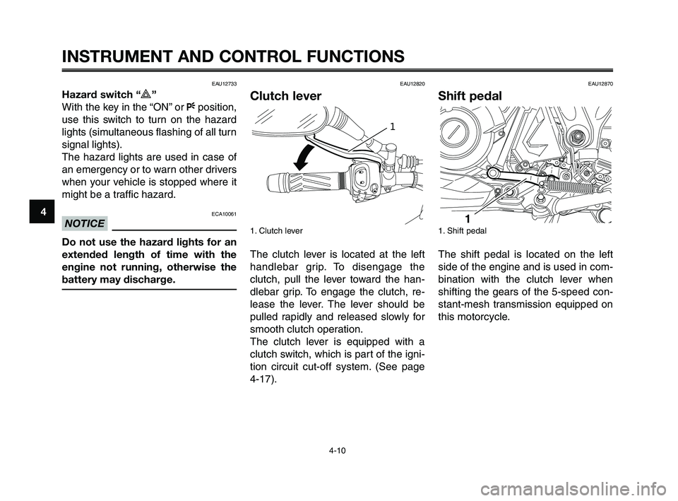
EAU12820
Clutch lever
1. Clutch lever
The clutch lever is located at the left
handlebar grip. To disengage the
clutch, pull the lever toward the han-
dlebar grip. To engage the clutch, re-
lease the lever. The lever should be
pulled rapidly and released slowly for
smooth clutch operation.
The clutch lever is equipped with a
clutch switch, which is part of the igni-
tion circuit cut-off system. (See page
4-17).
1
EAU12870
Shift pedal
1. Shift pedal
The shift pedal is located on the left
side of the engine and is used in com-
bination with the clutch lever when
shifting the gears of the 5-speed con-
stant-mesh transmission equipped on
this motorcycle.
XT660Z 04-04 ING-AUS:MY03 01-03 ING 11-05-2009 9:54 Pagina 4-10
Page 28 of 100

INSTRUMENT AND CONTROL FUNCTIONS
4-12
1
2
3
4
5
6
7
8
9
10
To close the fuel tank cap
1. Push the fuel tank cap into posi-
tion with the key inserted in the
lock.
2. Turn the key counterclockwise to
the original position, remove it,
and then close the lock cover.
TIP
The fuel tank cap cannot be closed
unless the key is in the lock. In addi-
tion, the key cannot be removed if the
cap is not properly closed and locked.
EWA11091
WARNING0
Make sure that the fuel tank cap is
properly closed after filling fuel.
Leaking fuel is a fire hazard.
EAU13221
Fuel
Make sure there is sufficient gasoline
in the tank.
EWA10881
WARNING0
Gasoline and gasoline vapors are
extremely flammable. To avoid fires
and explosions and to reduce the
risk of injury when refueling, follow
these instructions.
1. Before refueling, turn off the en-
gine and be sure that no one is
sitting on the vehicle. Never refuel
while smoking, or while in the
vicinity of sparks, open flames, or
other sources of ignition such as
the pilot lights of water heaters
and clothes dryers.
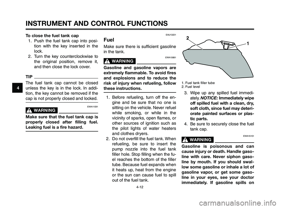
2. Do not overfill the fuel tank. When
refueling, be sure to insert the
pump nozzle into the fuel tank
filler hole. Stop filling when the fu-
el reaches the bottom of the filler
tube. Because fuel expands when
it heats up, heat from the engine
or the sun can cause fuel to spill
out of the fuel tank.
1. Fuel tank filler tube
2. Fuel level
3. Wipe up any spilled fuel immedi-
ately. NOTICE:Immediately wipe
off spilled fuel with a clean, dry,
soft cloth, since fuel may deteri-
orate painted surfaces or plas-
tic parts.
4. Be sure to securely close the fuel
tank cap.
EWA15151
WARNING0
Gasoline is poisonous and can
cause injury or death. Handle gaso-
line with care. Never siphon gaso-
line by mouth. If you should swal-
low some gasoline or inhale a lot of
gasoline vapor, or get some gaso-
line in your eyes, see your doctor
immediately. If gasoline spills on
XT660Z 04-04 ING-AUS:MY03 01-03 ING 11-05-2009 9:54 Pagina 4-12
Page 29 of 100

1
2
3
4
5
6
7
8
9
10
INSTRUMENT AND CONTROL FUNCTIONS
4-13
your skin, wash with soap and wa-
ter. If gasoline spills on your cloth-
ing, change your clothes.
EAU13390EAU13412
Fuel tank breather hose
1. Fuel tank breather hose
2. Clamp
Before operating the motorcycle:
●Check the fuel tank breather hose
connection.
●Check the fuel tank breather hose
for cracks or damage, and replace
it if damaged.
●Make sure that the fuel tank
breather hose is not blocked, and
clean it if necessary.
ECA11400
NOTICE
Use only unleaded gasoline. The use
of leaded gasoline will cause severe
damage to internal engine parts,
such as the valves and piston rings,
as well as to the exhaust system.
Your Yamaha engine has been de-
signed to use premium unleaded
gasoline with a research octane num-
ber of 95 or higher. If knocking (or
pinging) occurs, use a gasoline of a
different brand. Use of unleaded fuel
will extend spark plug life and reduce
maintenance costs.
Recommended fuel:
PREMIUM UNLEADED
GASOLINE ONLY
Fuel tank capacity:
23.0 L (6.07 US gal) (5.05 Imp.gal)
Fuel reserve amount (when the fuel
level warning light comes on):
6.7 L (1.77 US gal) (1.47 Imp.gal)
EAU13433
Catalytic converter
This model is equipped with a catalyt-
ic converter in the exhaust system.
EWA10862
WARNING0
The exhaust system is hot after op-
eration. To prevent a fire hazard or
burns:
●Do not park the vehicle near
possible fire hazards such as
grass or other materials that
easily burn.
●Park the vehicle in a place
where pedestrians or children
are not likely to touch the hot
exhaust system.
●Make sure that the exhaust
system has cooled down be-
fore doing any maintenance
work.
●Do not allow the engine to idle
more than a few minutes. Long
idling can cause a build-up of
heat.
XT660Z 04-04 ING-AUS:MY03 01-03 ING 11-05-2009 9:54 Pagina 4-13
Page 33 of 100

EWA10240
WARNING0
The vehicle must not be ridden
with the sidestand down, or if the
sidestand cannot be properly
moved up (or does not stay up),
otherwise the sidestand could con-
tact the ground and distract the
operator, resulting in a possible
loss of control. Yamaha’s ignition
circuit cut-off system has been de-
signed to assist the operator in ful-
filling the responsibility of raising
the sidestand before starting off.
Therefore, check this system regu-
larly as described below and have
a Yamaha dealer repair it if it does
not function properly.
EAU15301
Sidestand
1. Sidestand
The sidestand is located on the left
side of the frame. Raise the sidestand
or lower it with your foot while holding
the motorcycle upright.
TIP
The built-in sidestand switch is part of
the ignition circuit cut-off system,
which cuts the ignition in certain situa-
tions. (See further down for an expla-
nation of the ignition circuit cut-off sys-
tem.)
1
1
2
3
4
5
6
7
8
9
10
INSTRUMENT AND CONTROL FUNCTIONS
4-17
EAU15314
Ignition circuit cut-off
system
The ignition circuit cut-off system
(comprising the sidestand switch,
clutch switch and neutral switch) has
the following functions.
●It prevents starting when the
transmission is in gear and the
sidestand is up, but the clutch
lever is not pulled.
●It prevents starting when the
transmission is in gear and the
clutch lever is pulled, but the side-
stand is still down.
●It cuts the running engine when
the transmission is in gear and
the sidestand is moved down.
Periodically check the operation of the
ignition circuit cut-off system accord-
ing to the following procedure.
TIP
This check is most reliable if per-
formed with a warmed-up engine.
XT660Z 04-04 ING-AUS:MY03 01-03 ING 11-05-2009 9:55 Pagina 4-17
Page 34 of 100

INSTRUMENT AND CONTROL FUNCTIONS
WARNING0
If a malfunction is noted, have a Yamaha dealer
check the system before riding.
4-18
1
2
3
4
5
6
7
8
9
10
With the engine turned off:
1. Move the sidestand down.
2. Make sure that the engine stop switch is set to
“I”.
3. Turn the key on.
4. Shift the transmission into the neutral position.
5. Push the start switch.
Does the engine start?
With the engine still running:
6. Move the sidestand up.
7. Keep the clutch lever pulled.
8. Shift the transmission into gear.
9. Move the sidestand down.
Does the engine stall?
The neutral switch may not be working correctly.
The motorcycle should not be riddenuntil checked by a
Yamaha dealer.
The sidestand switch may not be working correctly.
The motorcycle should not be riddenuntil checked by a
Yamaha dealer.
The clutch switch may not be working correctly.
The motorcycle should not be riddenuntil checked by a
Yamaha dealer.
After the engine has stalled:
10. Move the sidestand up.
11. Keep the clutch lever pulled.
12. Push the start switch.
Does the engine start?
The system is OK. The motorcycle can be ridden.YES NO
NO YES
NO YES
XT660Z 04-04 ING-AUS:MY03 01-03 ING 11-05-2009 9:55 Pagina 4-18
Page 36 of 100

FOR YOUR SAFETY – PRE-OPERATION CHECKS
5-2
1
2
3
4
5
6
7
8
9
10
ITEM
Fuel
Engine oil
Coolant
Front brake
Rear brake
EAU15605
Before using this vehicle, check the following points:
CHECKS
Check fuel level in fuel tank.
Refuel if necessary.
Check fuel line for leakage.
Check oil level in oil tank.
If necessary, add recommended oil to specified level.
Check vehicle for oil leakage.
Check coolant level in reservoir.
If necessary, add recommended coolant to specified level.
Check cooling system for leakage.
Check operation.
If soft or spongy, have Yamaha dealer bleed hydraulic system.
Check brake pads for wear.
Replace if necessary.
Check fluid level in reservoir.
If necessary, add recommended brake fluid to specified level.
Check hydraulic system for leakage.
Check operation.
If soft or spongy, have Yamaha dealer bleed hydraulic system.
Check brake pads for wear.
Replace if necessary.
Check fluid level in reservoir.
If necessary, add recommended brake fluid to specified level.
Check hydraulic system for leakage.PAGE
4-12
7-9
7-12
4-11, 7-21, 7-22, 7-26
4-11, 7-21, 7-22, 7-27
XT660Z 05-07 ING-AUS:MY03 04-06 ING 11-05-2009 10:09 Pagina 2
Page 39 of 100

1
2
3
4
5
6
7
8
9
10
OPERATION AND IMPORTANT RIDING POINTS
EAU15951
Read the Owner's Manual carefully to
become familiar with all controls. If
there is a control or function you do not
understand, ask your Yamaha dealer.
EWA10271
WARNING0
Failure to familiarize yourself with
the controls can lead to loss of con-
trol, which could cause an accident
or injury.
6-1
EAU48020
TIP
This model is equipped with a lean an-
gle sensor to stop the engine in case
of a turnover. In this case, the multi-
function display indicates error code
30, but this is not a malfunction. Turn
the key to "OFF" and then to "ON" to
clear the error code. Failing to do so
will prevent the engine from starting
even though the engine will crank
when pushing the start switch.
EAUB1570
Starting the engine
In order for the ignition circuit cut-off
system to enable starting, one of the
following conditions must be met:
●The transmission is in the neutral
position.
●The transmission is in gear with
the clutch lever pulled and the
sidestand up.
EWA10290
WARNING0
●Before starting the engine,
check the function of the igni-
tion circuit cut-off system ac-
cording to the procedure de-
scribed on page 4-18.
●Never ride with the sidestand
down.
1. Turn the key to “ON” and make
sure that the engine stop switch is
set to “
I”.
XT660Z 05-07 ING-AUS:MY03 04-06 ING 11-05-2009 10:09 Pagina 5