horn YAMAHA XT660Z 2010 Owners Manual
[x] Cancel search | Manufacturer: YAMAHA, Model Year: 2010, Model line: XT660Z, Model: YAMAHA XT660Z 2010Pages: 100, PDF Size: 6.91 MB
Page 25 of 100

1
2
3
4
5
6
7
8
9
10
INSTRUMENT AND CONTROL FUNCTIONS
4-9
EAU12348
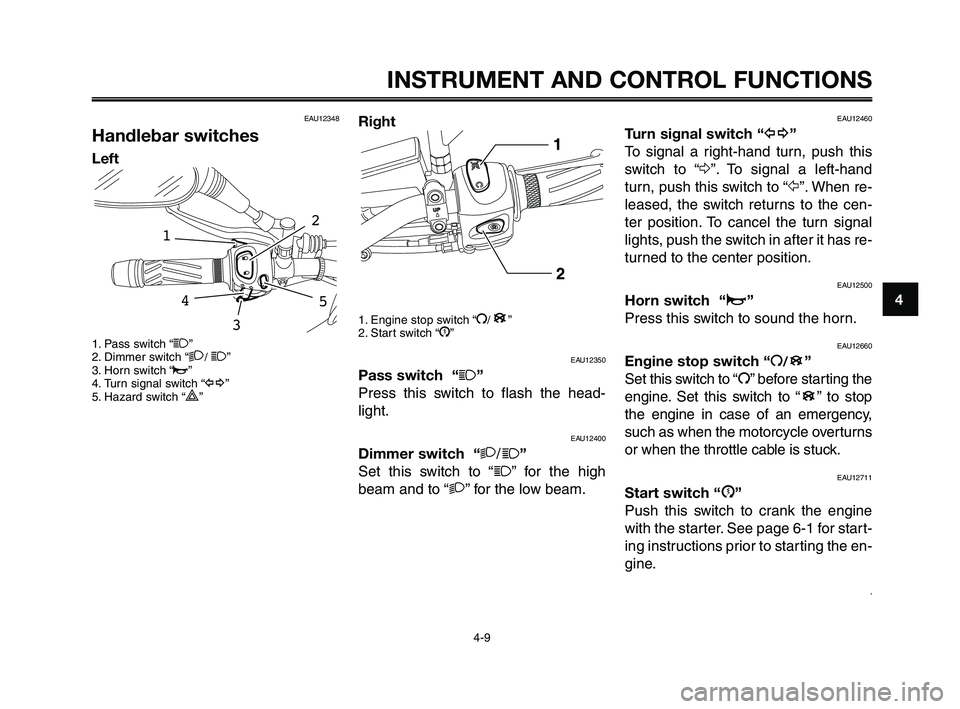
Handlebar switches
Left
1. Pass switch “1”
2. Dimmer switch “2/ 1”
3. Horn switch “o”
4. Turn signal switch “y”
5. Hazard switch “
r”
54
2
1
3
Right
1. Engine stop switch “I/”
2. Start switch “J”
EAU12350
Pass switch “1”
Press this switch to flash the head-
light.
EAU12400
Dimmer switch “2/1”
Set this switch to “
1” for the high
beam and to “2” for the low beam.
B
EAU12460
Turn signal switch “y”
To signal a right-hand turn, push this
switch to “Δ”. To signal a left-hand
turn, push this switch to “Ÿ”. When re-
leased, the switch returns to the cen-
ter position. To cancel the turn signal
lights, push the switch in after it has re-
turned to the center position.
EAU12500
Horn switch “o”
Press this switch to sound the horn.
EAU12660
Engine stop switch “I/”
Set this switch to “I” before starting the
engine. Set this switch to “ ” to stop
the engine in case of an emergency,
such as when the motorcycle overturns
or when the throttle cable is stuck.
EAU12711
Start switch “J”
Push this switch to crank the engine
with the starter. See page 6-1 for start-
ing instructions prior to starting the en-
gine.
,
B
B
XT660Z 04-04 ING-AUS:MY03 01-03 ING 11-05-2009 9:54 Pagina 4-9
Page 94 of 100

INDEX
1
2
3
4
5
6
7
8
9
10
Dimmer switch ................................4-9
Engine stop switch .........................4-9
Hazard switch ...............................4-10
Horn switch .....................................4-9
Pass switch .....................................4-9
Start switch .....................................4-9
Turn signal switch ...........................4-9
Headlight bulb, replacing..................7-33
High beam indicator light ...................4-4
Horn switch ........................................4-9
I
Identification numbers ......................10-1
Idling speed, checking .....................7-15
Ignition circuit cut-off system............4-17
Checking operation procedure......4-18
Immobilizer system ............................4-1
Immobilizer system indicator light ......4-4
Indicator and warning lights ...............4-3
Coolant temperature warning light..4-4
Engine trouble warning light ...........4-4
High beam indicator light ................4-4
Immobilizer system indicator light...4-4
Neutral indicator light ......................4-4
Turn signal indicator light ................4-3
Instruments ........................................3-3
Instrument and control functions........4-1
K
Key identification number .................10-1
Keys ...................................................4-1L
Labels (location of important labels) ..1-1
License plate light bulb, replacing ....7-35
Location of important labels ...............1-1
Loading ..............................................2-3
Lubricating the brake and clutch
levers ............................................7-26
Lubricating the brake pedal..............7-27
Lubricating the cables ......................7-25
Lubricating the drive chain ...............7-25
Lubricating the sidestand .................7-27
Lubricating the throttle grip
and cable ......................................7-26
Lubricating the swingarm pivots.......7-28
M
Main switch/steering lock ...................4-2
Model label .......................................10-2
Motorcycle noise regulation
(for Australia) ................................10-2
Multi-function display..........................4-5
Clock mode .....................................4-7
Self-diagnosis devices ....................4-7
Tachometer .....................................4-6
Tripmeter and tachometer modes ...4-6
N
Neutral indicator light .........................4-4
O
Oil filter element ..............................7-10
Operation and important riding
points ..............................................6-1Owner’s tool kit...................................7-1
P
Panels, removing and installing .........7-6
Parking ...............................................6-4
Pass switch ........................................4-9
Periodic maintenance
and adjustment ...............................7-1
Periodic maintenance chart for
the emission control system ...........7-2
Pre-operation check list......................5-2
Pre-operation checks .........................5-1
R
Rear suspension, lubricating............7-27
Rear wheel .......................................7-38
Installing........................................7-39
Removing......................................7-38
Record the identification numbers ...10-1
S
Safety information ..............................2-1
Seat ..................................................4-14
Self-diagnosis devices .......................4-7
Shift pedal ........................................4-10
Shifting ...............................................6-2
Shock absorber assembly
(adjusting) .....................................4-16
Sidestand .........................................4-17
Sidestand, checking and lubricating ..7-27
Sidestand switch, checking ..............4-18
Spark plug, checking..........................7-8
XT660Z 08-10 ING-AUS:MY03 07-10 ING 11-05-2009 10:10 Pagina 2