YAMAHA YZ250F 2001 Owners Manual
Manufacturer: YAMAHA, Model Year: 2001, Model line: YZ250F, Model: YAMAHA YZ250F 2001Pages: 656, PDF Size: 24.86 MB
Page 201 of 656
INSP
ADJ
CONTROLE ET REGLAGE DU JEU DE SOUPAPES
VENTILSPIEL KONTROLLIEREN UND EINSTELLEN
CONTROLLO E REGOLAZIONE DEL GIOCO DELLE VALVOLE
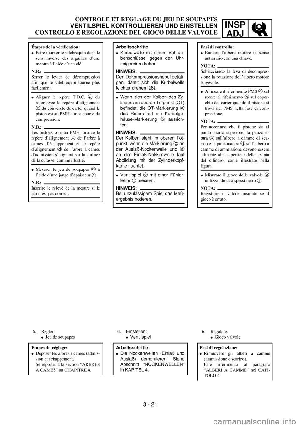
Arbeitsschritte
lKurbelwelle mit einem Schrau-
benschlüssel gegen den Uhr-
zeigersinn drehen.
HINWEIS:
Den Dekompressionshebel betäti-
gen, damit sich die Kurbelwelle
leichter drehen läßt.
lWenn sich der Kolben des Zy-
linders im oberen Totpunkt (OT)
befindet, die OT-Markierung a
des Rotors auf die Kurbelge-
häuse-Markierung b ausrich-
ten.
HINWEIS:
Der Kolben steht im oberen Tot-
punkt, wenn die Markierung c an
der Auslaß-Nockenwelle und d
an der Einlaß-Nokkenwelle laut
Abbildung mit der Zylinderkopf-
kante fluchtet.
lVentilspiel e mit einer Fühler-
lehre 1 messen.
HINWEIS:
Bei unzulässigem Spiel das Meß-
ergebnis notieren.
6. Einstellen:
lVentilspiel
Arbeitsschritte:
lDie Nockenwellen (Einlaß und
Auslaß) demontieren. Siehe
Abschnitt “NOCKENWELLEN”
in KAPITEL 4.
Étapes de la vérification:
lFaire tourner le vilebrequin dans le
sens inverse des aiguilles d’une
montre à l’aide d’une clé.
N.B.:
Serrer le levier de décompression
afin que le vilebrequin tourne plus
facilement.
lAligner le repère T.D.C. a du
rotor avec le repère d’alignement
b du couvercle de carter quand le
piston est au PMH sur sa course de
compression.
N.B.:
Les pistons sont au PMH lorsque le
repère d’alignement c de l’arbre à
cames d’échappement et le repère
d’alignement d de l’arbre à cames
d’admission s’alignent sur la surface
de la culasse, comme illustré.
lMesurer le jeu de soupapes e à
l’aide d’une jauge d’épaisseur 1.
N.B.:
Inscrire le relevé de la mesure si le
jeu n’est pas correct.
6. Régler:
lJeu de soupapes
Etapes du réglage:
lDéposer les arbres à cames (admis-
sion et échappement).
Se reporter à la section “ARBRES
A CAMES” au CHAPITRE 4.
Fasi di controllo:
lRuotare l’albero motore in senso
antiorario con una chiave.
NOTA:
Schiacciando la leva di decompres-
sione la rotazione dell’albero motore
è agevole.
lAllineare il riferimento PMS a sul
rotore al riferimento b sul coper-
chio del carter quando il pistone si
trova nel PMS nella fase di com-
pressione.
NOTA:
Per accertarsi che il pistone sia al
punto morto superiore, la punzona-
tura c sull’albero a camme di sca-
rico e la punzonatura d sull’albero a
camme di ammissione devono essere
allineate alla superficie della testata
del cilindro, come illustrato nella
figura.
lMisurare il gioco delle valvole e
utilizzando uno spessimetro 1.
NOTA:
Registrare il valore misurato se il
gioco è errato.
6. Regolare:
lGioco valvole
Fasi di regolazione:
lRimuovere gli alberi a camme
(ammissione e scarico).
Fare riferimento al paragrafo
“ALBERI A CAMME” nel CAPI-
TOLO 4.
3 - 21
Page 202 of 656
3 - 22
INSP
ADJ
VALVE CLEARANCE INSPECTION AND ADJUSTMENT
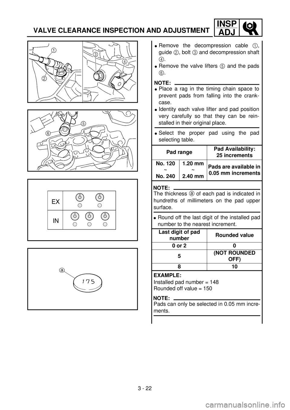
lRemove the decompression cable 1,
guide 2, bolt 3 and decompression shaft
4.
lRemove the valve lifters 5 and the pads
6.
NOTE:
lPlace a rag in the timing chain space to
prevent pads from falling into the crank-
case.
lIdentity each valve lifter and pad position
very carefully so that they can be rein-
stalled in their original place.
lSelect the proper pad using the pad
selecting table.
Pad rangePad Availability:
25 increments
No. 120
~
No. 2401.20 mm
~
2.40 mmPads are available in
0.05 mm increments
NOTE:
The thickness a of each pad is indicated in
hundreths of millimeters on the pad upper
surface.
lRound off the last digit of the installed pad
number to the nearest increment.
Last digit of pad
numberRounded value
0 or 2 0
5(NOT ROUNDED
OFF)
810
EXAMPLE:
Installed pad number = 148
Rounded off value = 150
NOTE:
Pads can only be selected in 0.05 mm incre-
ments.
Page 203 of 656
INSP
ADJ
CONTROLE ET REGLAGE DU JEU DE SOUPAPES
VENTILSPIEL KONTROLLIEREN UND EINSTELLEN
CONTROLLO E REGOLAZIONE DEL GIOCO DELLE VALVOLE
lDekompressionszug 1, Füh-
rung 2, Schraube 3 und De-
kompressionswelle 4 ausbau-
en.
lTassenstößel 5 und Ventil-
plättchen 6 demontieren.
HINWEIS:
lVor dem Ausbau der Ventilplätt-
chen das Kurbelgehäuse mit ei-
nem sauberen Tuch abdecken,
damit die Ventilplättchen nicht
hineinfallen können.
lTassenstößel und Ventilplätt-
chen für den späteren Wieder-
einbau markieren.
lDie Ventilplättchen gemäß Ta-
belle wählen
StärkenbereichVerfügbare Ven-
tilplättchen:
25 verschie-
dene Stärken
Nr. 120
–
Nr. 2401,20 mm
–
2,40 mmIn Abstufungen
von 0,05 mm
erhältlich
HINWEIS:
Die Stärke a ist in Hundertstelmil-
limetern auf der Oberfläche der
Ventilplättchen angegeben.
lHundertstel gemäß Tabelle run-
den.
Letzte Ziffer auf
dem PlättchenGerundeter Wert
0 oder 2 0
5NICHT
GERUNDET
810
BEISPIEL:
Nr. des ausgebauten Ventilplätt-
chens = 148
Gerundeter Wert = 150
HINWEIS:
Ventilplättchen sind nur in Abstu-
fungen von 0,05 mm erhältlich.
lDéposer le câble de décompression
1, le guide 2, le boulon 3 et l’a
de décompresseur 4.
lDéposer les poussoirs de soupapes
5 et les cales 6.
N.B.:
lPlacer un chiffon dans la cavité de
la chaîne de distribution pour
empêcher les cales de tomber dans
le carter.
lNoter la position de chaque pous-
soir de soupape et de chaque cale
afin de pouvoir les remettre en
place dans leur position d’origine.
lChoisir la cale correcte à l’aide du
tableau suivant:
Epaisseur de caleNombre d’épais-
seurs disponibles:
25
N˚ 120
à
N˚ 2401,20 mm
à
2,40 mm Les cales sont dis-
ponibles par
incréments de
0,05 mm.
N.B.:
L’épaisseur a de chaque cale est indi-
quée en centièmes de millimètres sur
la face de la cale.
lArrondir le dernier chiffre de la cale
installée à l’épaisseur de cale dispo-
nible la plus proche.
Dernier chiffre du
numéro de cale Chiffre arrondi
0 ou 2 0
5 (PAS ARRONDI)
810
EXEMPLE:
Numéro de cale installée = 148
Valeur arrondie = 150
N.B.:
Les cales ne peuvent être sélection-
nées que par incréments de 0,05 mm.
lRimuovere il cavo di decompres-
sione 1, la guida 2, il bullone 3
e l’albero di decompressione 4.
lRimuovere gli alzavalvola 5 e gli
spessori 6.
NOTA:
lCollocare uno straccio nello spazio
della catena di distribuzione per
evitare che gli spessori cadano nel
carter.
lIdentificare molto attentamente la
posizione di ogni alzavalvola e di
ogni spessore in modo tale da
poterli rimontare nella posizione
originale.
lScegliere lo spessore giusto utiliz-
zando la tabella apposita.
Gamma di spes-
soriDisponibilità spes-
sori:
a 25 incrementi
N. 120
~
N. 2401,20 mm
~
2,40 mmGli spessori sono
disponibili in
incrementi di
0,05 mm
NOTA:
Lo spessore a di ogni spessore è indi-
cato in centinaia di millimetri sulla
superficie superiore dello spessore.
lArrotondare l’ultima cifra del
numero dello spessore installato
fino all’incremento più vicino.
Ultima cifra del
numero dello
spessoreValore
arrotondato
0 o 2 0
5(NON ARRO-
TONDATO)
810
ESEMPIO:
Numero dello spessore installato =
148
Valore arrotondato = 150
NOTA:
È possibile selezionare gli spessori
esclusivamente in incrementi di 0,05
mm.
3 - 22
Page 204 of 656
3 - 23
INSP
ADJ
VALVE CLEARANCE INSPECTION AND ADJUSTMENT
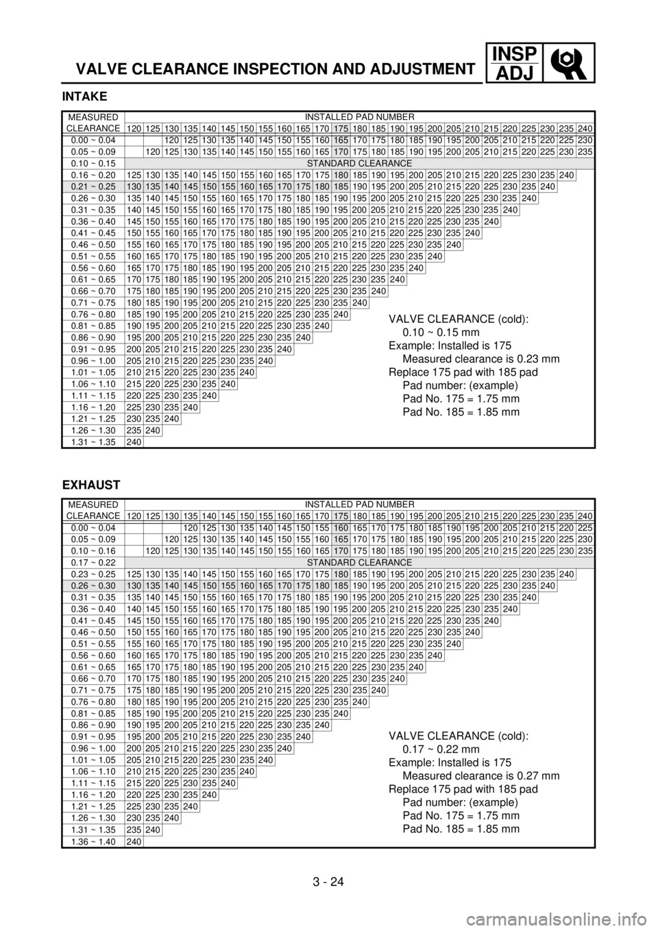
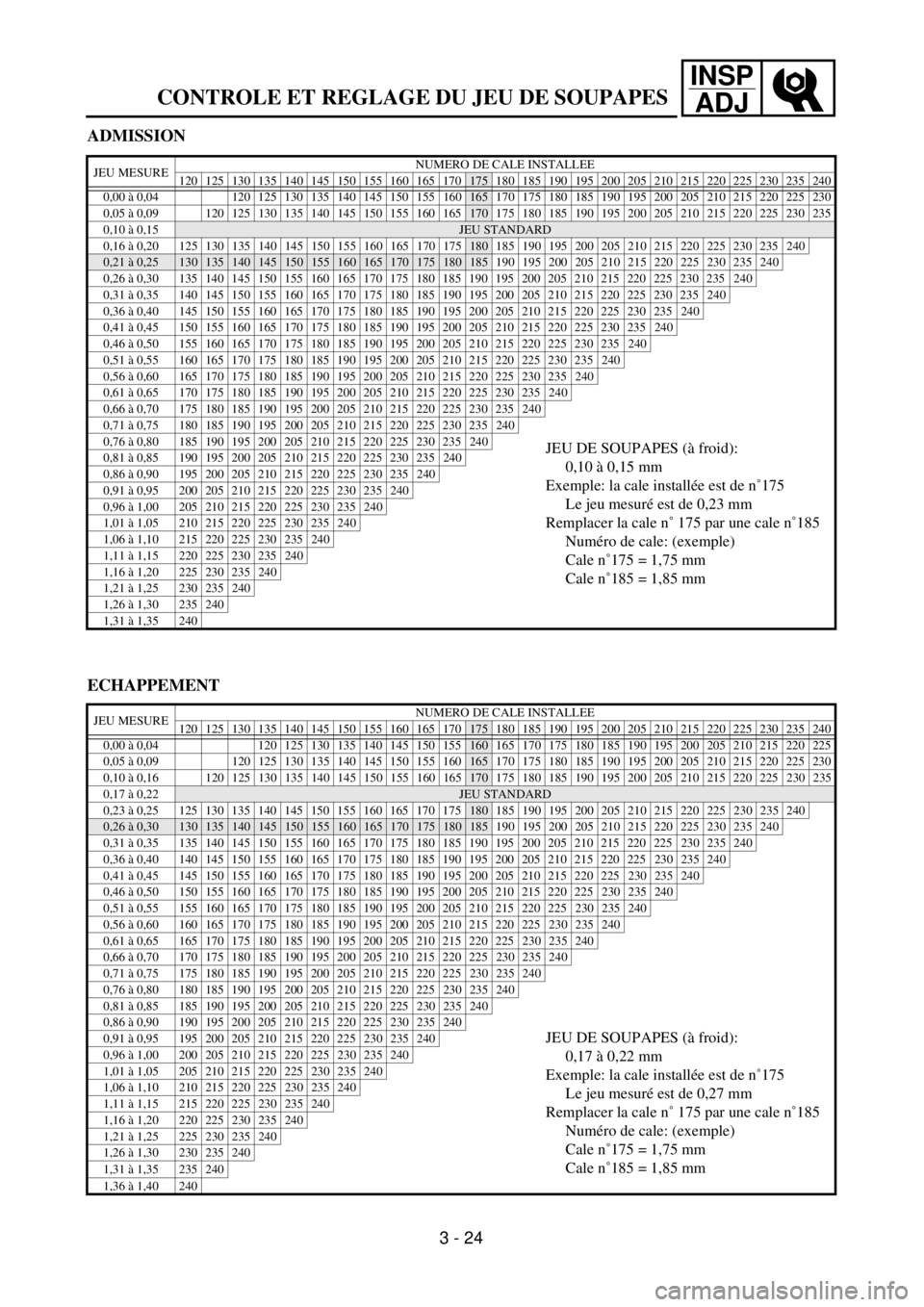
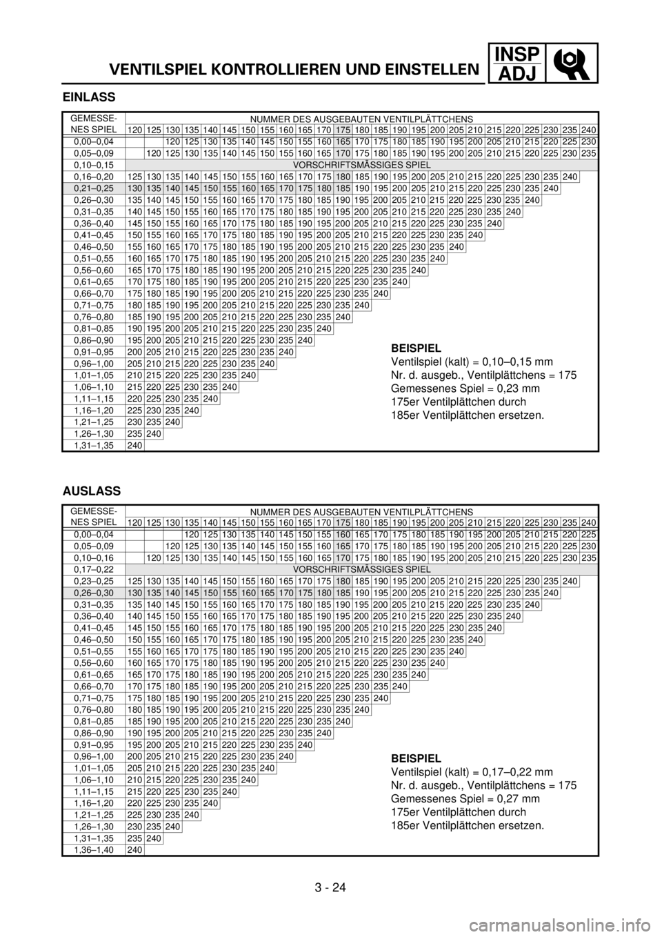
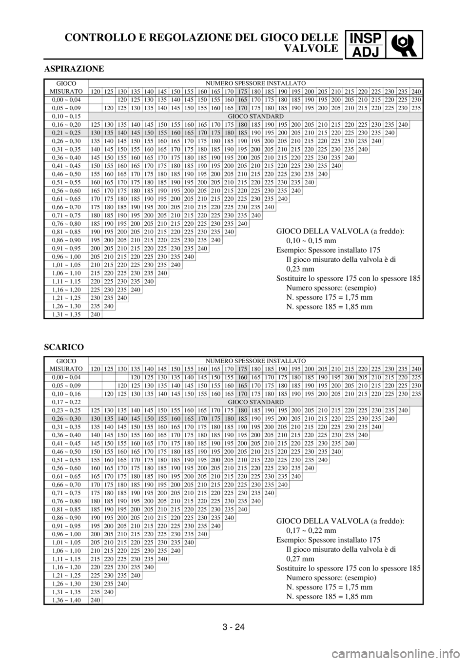
lLocate the rounded-off value and the
measured valve clearance in the chart
“PAD SELECTION TABLE”. The field
where these two coordinates intersect
shows the new pad number to use.
NOTE:
Use the new pad number only as a guide
when verifying the valve clearance adjust-
ment.
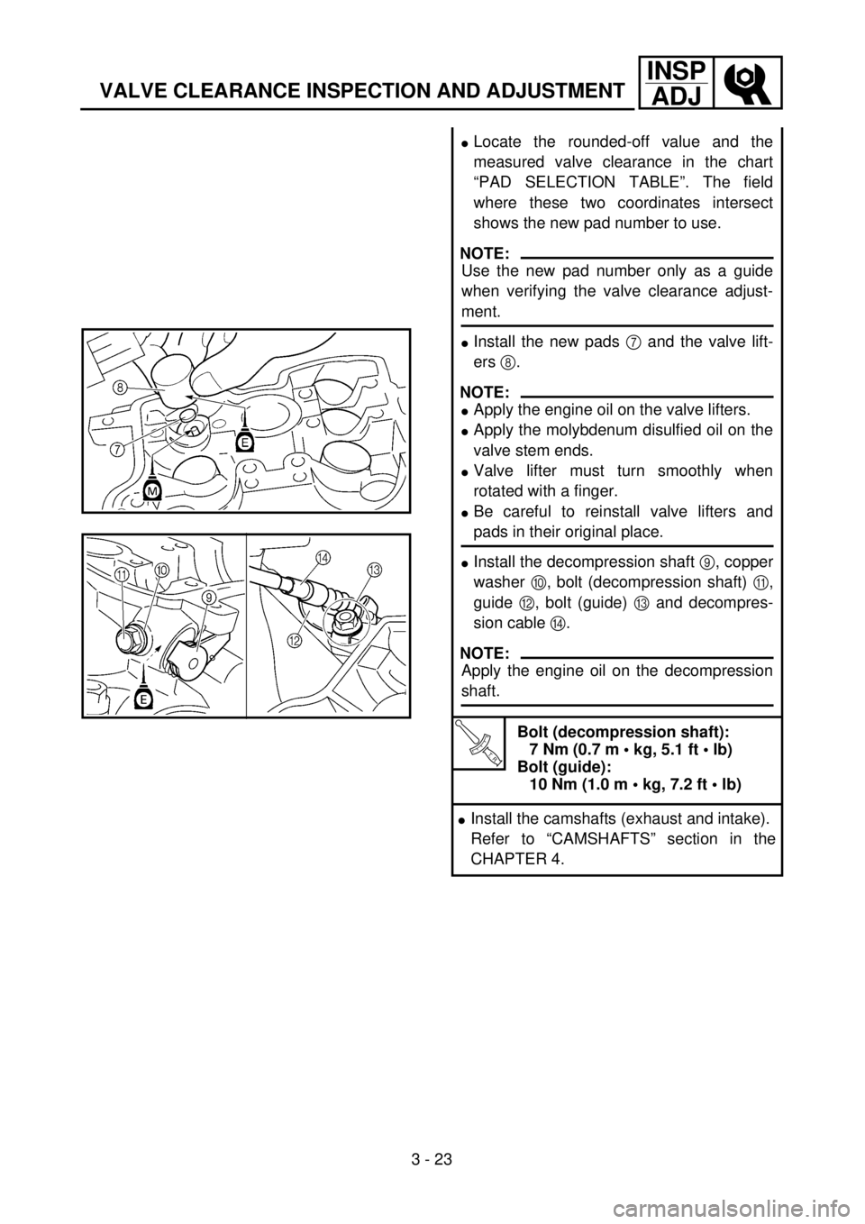
lInstall the new pads 7 and the valve lift-
ers 8.
NOTE:
lApply the engine oil on the valve lifters.
lApply the molybdenum disulfied oil on the
valve stem ends.
lValve lifter must turn smoothly when
rotated with a finger.
lBe careful to reinstall valve lifters and
pads in their original place.
lInstall the decompression shaft 9, copper
washer 0, bolt (decompression shaft) A,
guide B, bolt (guide) C and decompres-
sion cable D.
NOTE:
Apply the engine oil on the decompression
shaft.
T R..
Bolt (decompression shaft):
7 Nm (0.7 m • kg, 5.1 ft • lb)
Bolt (guide):
10 Nm (1.0 m • kg, 7.2 ft • lb)
lInstall the camshafts (exhaust and intake).
Refer to “CAMSHAFTS” section in the
CHAPTER 4.
Page 205 of 656
INSP
ADJ
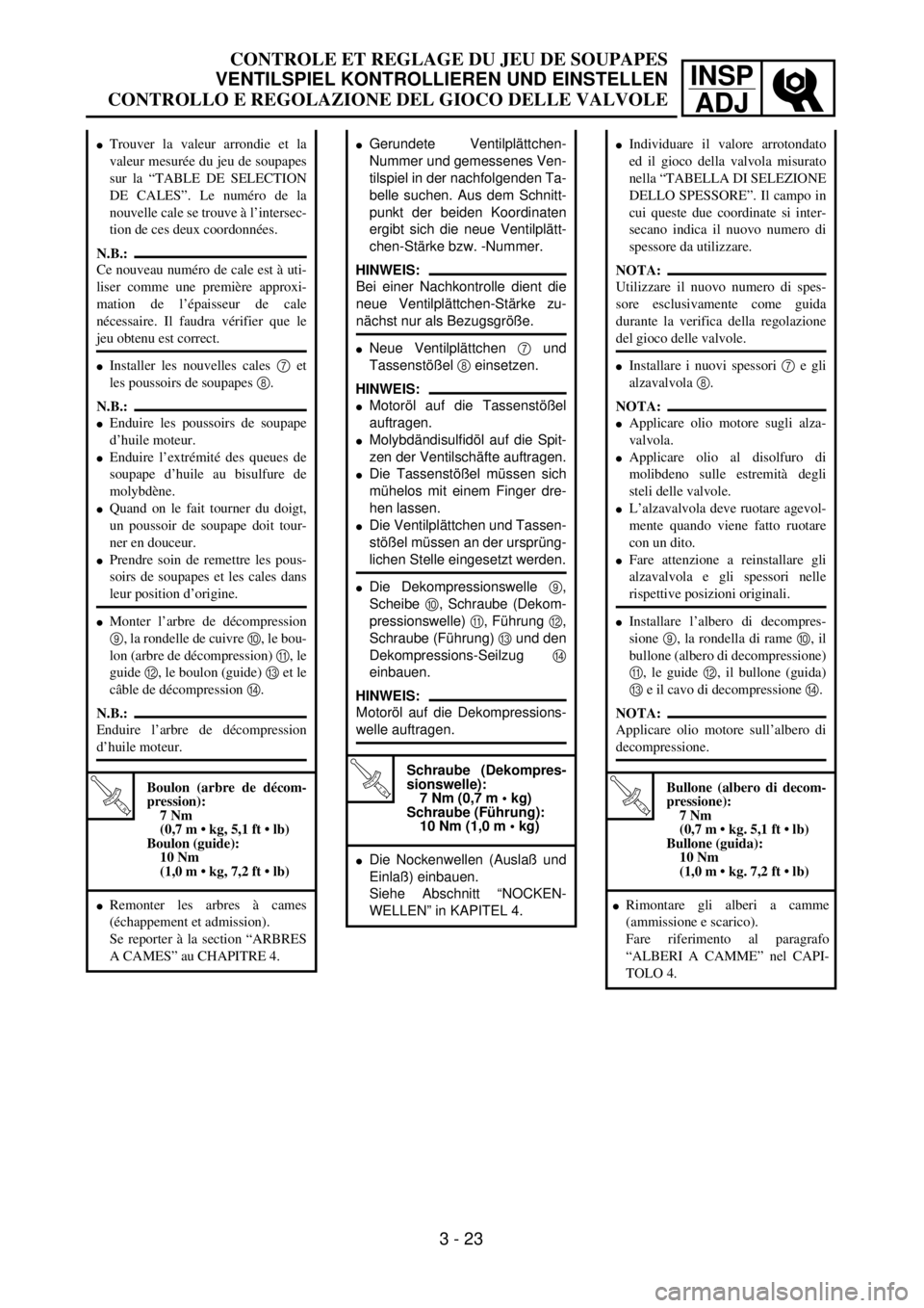
lGerundete Ventilplättchen-
Nummer und gemessenes Ven-
tilspiel in der nachfolgenden Ta-
belle suchen. Aus dem Schnitt-
punkt der beiden Koordinaten
ergibt sich die neue Ventilplätt-
chen-Stärke bzw. -Nummer.
HINWEIS:
Bei einer Nachkontrolle dient die
neue Ventilplättchen-Stärke zu-
nächst nur als Bezugsgröße.
lNeue Ventilplättchen 7 und
Tassenstößel 8 einsetzen.
HINWEIS:
lMotoröl auf die Tassenstößel
auftragen.
lMolybdändisulfidöl auf die Spit-
zen der Ventilschäfte auftragen.
lDie Tassenstößel müssen sich
mühelos mit einem Finger dre-
hen lassen.
lDie Ventilplättchen und Tassen-
stößel müssen an der ursprüng-
lichen Stelle eingesetzt werden.
lDie Dekompressionswelle 9,
Scheibe 0, Schraube (Dekom-
pressionswelle) A, Führung B,
Schraube (Führung) C und den
Dekompressions-Seilzug D
einbauen.
HINWEIS:
Motoröl auf die Dekompressions-
welle auftragen.
T R..
Schraube (Dekompres-
sionswelle):
7 Nm (0,7 m • kg)
Schraube (Führung):
10 Nm (1,0 m • kg)
lDie Nockenwellen (Auslaß und
Einlaß) einbauen.
Siehe Abschnitt “NOCKEN-
WELLEN” in KAPITEL 4.
lTrouver la valeur arrondie et la
valeur mesurée du jeu de soupapes
sur la “TABLE DE SELECTION
DE CALES”. Le numéro de la
nouvelle cale se trouve à l’intersec-
tion de ces deux coordonnées.
N.B.:
Ce nouveau numéro de cale est à uti-
liser comme une première approxi-
mation de l’épaisseur de cale
nécessaire. Il faudra vérifier que le
jeu obtenu est correct.
lInstaller les nouvelles cales 7 et
les poussoirs de soupapes 8.
N.B.:
lEnduire les poussoirs de soupape
d’huile moteur.
lEnduire l’extrémité des queues de
soupape d’huile au bisulfure de
molybdène.
lQuand on le fait tourner du doigt,
un poussoir de soupape doit tour-
ner en douceur.
lPrendre soin de remettre les pous-
soirs de soupapes et les cales dans
leur position d’origine.
lMonter l’arbre de décompression
9, la rondelle de cuivre 0, le bou-
lon (arbre de décompression) A, le
guide B, le boulon (guide) C et le
câble de décompression D.
N.B.:
Enduire l’arbre de décompression
d’huile moteur.
T R..
Boulon (arbre de décom-
pression):
7 Nm
(0,7 m • kg, 5,1 ft • lb)
Boulon (guide):
10 Nm
(1,0 m • kg, 7,2 ft • lb)
lRemonter les arbres à cames
(échappement et admission).
Se reporter à la section “ARBRES
A CAMES” au CHAPITRE 4.
lIndividuare il valore arrotondato
ed il gioco della valvola misurato
nella “TABELLA DI SELEZIONE
DELLO SPESSORE”. Il campo in
cui queste due coordinate si inter-
secano indica il nuovo numero di
spessore da utilizzare.
NOTA:
Utilizzare il nuovo numero di spes-
sore esclusivamente come guida
durante la verifica della regolazione
del gioco delle valvole.
lInstallare i nuovi spessori 7 e gli
alzavalvola 8.
NOTA:
lApplicare olio motore sugli alza-
valvola.
lApplicare olio al disolfuro di
molibdeno sulle estremità degli
steli delle valvole.
lL’alzavalvola deve ruotare agevol-
mente quando viene fatto ruotare
con un dito.
lFare attenzione a reinstallare gli
alzavalvola e gli spessori nelle
rispettive posizioni originali.
lInstallare l’albero di decompres-
sione 9, la rondella di rame 0, il
bullone (albero di decompressione)
A, le guide B, il bullone (guida)
C e il cavo di decompressione D.
NOTA:
Applicare olio motore sull’albero di
decompressione.
T R..
Bullone (albero di decom-
pressione):
7 Nm
(0,7 m • kg. 5,1 ft • lb)
Bullone (guida):
10 Nm
(1,0 m • kg. 7,2 ft • lb)
lRimontare gli alberi a camme
(ammissione e scarico).
Fare riferimento al paragrafo
“ALBERI A CAMME” nel CAPI-
TOLO 4.
3 - 23
CONTROLE ET REGLAGE DU JEU DE SOUPAPES
VENTILSPIEL KONTROLLIEREN UND EINSTELLEN
CONTROLLO E REGOLAZIONE DEL GIOCO DELLE VALVOLE
Page 206 of 656
3 - 24
INSP
ADJ
VALVE CLEARANCE INSPECTION AND ADJUSTMENT
INTAKE
MEASURED
CLEARANCEINSTALLED PAD NUMBER
120 125 130 135 140 145 150 155 160 165 170
175 180 185 190 195 200 205 210 215 220 225 230 235 240
0.00 ~ 0.04 120 125 130 135 140 145 150 155
160165 170 175 180 185 190 195 200 205 210 215 220 225 230
0.05 ~ 0.09
120 125 130 135 140 145 150 155 160 165170 175 180 185 190 195 200 205 210 215 220 225 230 235
0.10 ~ 0.15
STANDARD CLEARANCE
0.16 ~ 0.20125130135140145150155160165170175180 185 190 195 200 205 210 215 220 225 230 235240
0.21 ~ 0.25130135140145150155160165170175180185 190 195 200 205 210 215 220 225 230 235240
0.26 ~ 0.30 135 140 145 150 155 160 165 170 175 180 185 190 195 200 205 210 215 220 225 230 235240
0.31 ~ 0.35 140 145 150 155 160 165 170 175 180 185 190 195 200 205 210 215 220 225 230 235240
0.36 ~ 0.40 145 150 155 160 165 170 175 180 185 190 195 200 205 210 215 220 225 230 235240
0.41 ~ 0.45 150 155 160 165 170 175 180 185 190 195 200 205 210 215 220 225 230 235240
0.46 ~ 0.50 155 160 165 170 175 180 185 190 195 200 205 210 215 220 225 230 235240
0.51 ~ 0.55 160 165 170 175 180 185 190 195 200 205 210 215 220 225 230 235240
0.56 ~ 0.60 165 170 175 180 185 190 195 200 205 210 215 220 225 230 235240
0.61 ~ 0.65 170 175 180 185 190 195 200 205 210 215 220 225 230 235240
0.66 ~ 0.70 175 180 185 190 195 200 205 210 215 220 225 230 235240
0.71 ~ 0.75 180 185 190 195 200 205 210 215 220 225 230 235240
0.76 ~ 0.80 185 190 195 200 205 210 215 220 225 230 235240VALVE CLEARANCE (cold):
0.10 ~ 0.15 mm
Example: Installed is 175
Measured clearance is 0.23 mm
Replace 175 pad with 185 pad
Pad number: (example)
Pad No. 175 = 1.75 mm
Pad No. 185 = 1.85 mm0.81 ~ 0.85 190 195 200 205 210 215 220 225 230 235240
0.86 ~ 0.90 195 200 205 210 215 220 225 230 235240
0.91 ~ 0.95 200 205 210 215 220 225 230 235240
0.96 ~ 1.00 205 210 215 220 225 230 235240
1.01 ~ 1.05 210 215 220 225 230 235240
1.06 ~ 1.10 215 220 225 230 235240
1.11 ~ 1.15 220 225 230 235240
1.16 ~ 1.20 225 230 235240
1.21 ~ 1.25 230 235240
1.26 ~ 1.30 235240
1.31 ~ 1.35 240
EXHAUST
MEASURED
CLEARANCEINSTALLED PAD NUMBER
120 125 130 135 140 145 150 155 160 165 170
175 180 185 190 195 200 205 210 215 220 225 230 235 240
0.00 ~ 0.04 120 125 130 135 140 145 150 155
160 165 170 175 180 185 190 195 200 205 210 215 220 225
0.05 ~ 0.09
120 125 130 135 140 145 150 155 160165 170 175 180 185 190 195 200 205 210 215 220 225 230
0.10 ~ 0.16
120125130135140145150155160165170 175 180 185 190 195 200 205 210 215 220 225230235
0.17 ~ 0.22STANDARD CLEARANCE
0.23 ~ 0.25 125 130 135 140 145 150 155 160 165 170 175
180 185 190 195 200 205 210 215 220 225230235 240
0.26 ~ 0.30130135140145150155160165170175180185 190 195 200 205 210 215 220 225230235240
0.31 ~ 0.35 135 140 145 150 155 160 165 170 175 180 185 190 195 200 205 210 215 220 225230235240
0.36 ~ 0.40 140 145 150 155 160 165 170 175 180 185 190 195 200 205 210 215 220 225230235240
0.41 ~ 0.45 145 150 155 160 165 170 175 180 185 190 195 200 205 210 215 220 225230235240
0.46 ~ 0.50 150 155 160 165 170 175 180 185 190 195 200 205 210 215 220 225230235240
0.51 ~ 0.55 155 160 165 170 175 180 185 190 195 200 205 210 215 220 225230235240
0.56 ~ 0.60 160 165 170 175 180 185 190 195 200 205 210 215 220 225230235240
0.61 ~ 0.65 165 170 175 180 185 190 195 200 205 210 215 220 225230235240
0.66 ~ 0.70 170 175 180 185 190 195 200 205 210 215 220 225230235240
0.71 ~ 0.75 175 180 185 190 195 200 205 210 215 220 225230235240
0.76 ~ 0.80 180 185 190 195 200 205 210 215 220 225230235240
0.81 ~ 0.85 185 190 195 200 205 210 215 220 225230235240
0.86 ~ 0.90 190 195 200 205 210 215 220 225230235240
VALVE CLEARANCE (cold):
0.17 ~ 0.22 mm
Example: Installed is 175
Measured clearance is 0.27 mm
Replace 175 pad with 185 pad
Pad number: (example)
Pad No. 175 = 1.75 mm
Pad No. 185 = 1.85 mm0.91 ~ 0.95 195 200 205 210 215 220 225230235240
0.96 ~ 1.00 200 205 210 215 220 225230235240
1.01 ~ 1.05 205 210 215 220 225230235240
1.06 ~ 1.10 210 215 220 225230235240
1.11 ~ 1.15 215 220 225230235240
1.16 ~ 1.20 220 225230235240
1.21 ~ 1.25 225230235240
1.26 ~ 1.30 230235240
1.31 ~ 1.35 235240
1.36 ~ 1.40 240
Page 207 of 656
INSP
ADJ
CONTROLE ET REGLAGE DU JEU DE SOUPAPES
ADMISSION
JEU MESURENUMERO DE CALE INSTALLEE
120 125 130 135 140 145 150 155 160 165 170175 180 185 190 195 200 205 210 215 220 225 230 235 240
0,00 à 0,04 120 125 130 135 140 145 150 155
160165 170 175 180 185 190 195 200 205 210 215 220 225 230
0,05 à 0,09
120 125 130 135 140 145 150 155 160 165170 175 180 185 190 195 200 205 210 215 220 225 230 235
0,10 à 0,15
JEU STANDARD
0,16 à 0,20125130135140145150155160165170175180 185 190 195 200 205 210 215 220 225 230 235240
0,21 à 0,25130135140145150155160165170175180185 190 195 200 205 210 215 220 225 230 235240
0,26 à 0,30 135 140 145 150 155 160 165 170 175 180 185 190 195 200 205 210 215 220 225 230 235240
0,31 à 0,35 140 145 150 155 160 165 170 175 180 185 190 195 200 205 210 215 220 225 230 235240
0,36 à 0,40 145 150 155 160 165 170 175 180 185 190 195 200 205 210 215 220 225 230 235240
0,41 à 0,45 150 155 160 165 170 175 180 185 190 195 200 205 210 215 220 225 230 235240
0,46 à 0,50 155 160 165 170 175 180 185 190 195 200 205 210 215 220 225 230 235240
0,51 à 0,55 160 165 170 175 180 185 190 195 200 205 210 215 220 225 230 235240
0,56 à 0,60 165 170 175 180 185 190 195 200 205 210 215 220 225 230 235240
0,61 à 0,65 170 175 180 185 190 195 200 205 210 215 220 225 230 235240
0,66 à 0,70 175 180 185 190 195 200 205 210 215 220 225 230 235240
0,71 à 0,75 180 185 190 195 200 205 210 215 220 225 230 235240
0,76 à 0,80 185 190 195 200 205 210 215 220 225 230 235240JEU DE SOUPAPES (à froid):
0,10 à 0,15 mm
Exemple: la cale installée est de n˚175
Le jeu mesuré est de 0,23 mm
Remplacer la cale n˚ 175 par une cale n˚185
Numéro de cale: (exemple)
Cale n˚175 = 1,75 mm
Cale n˚185 = 1,85 mm0,81 à 0,85 190 195 200 205 210 215 220 225 230 235240
0,86 à 0,90 195 200 205 210 215 220 225 230 235240
0,91 à 0,95 200 205 210 215 220 225 230 235240
0,96 à 1,00 205 210 215 220 225 230 235240
1,01 à 1,05 210 215 220 225 230 235240
1,06 à 1,10 215 220 225 230 235240
1,11 à 1,15 220 225 230 235240
1,16 à 1,20 225 230 235240
1,21 à 1,25 230 235240
1,26 à 1,30 235240
1,31 à 1,35 240
ECHAPPEMENT
JEU MESURENUMERO DE CALE INSTALLEE
120 125 130 135 140 145 150 155 160 165 170175 180 185 190 195 200 205 210 215 220 225 230 235 240
0,00 à 0,04 120 125 130 135 140 145 150 155
160 165 170 175 180 185 190 195 200 205 210 215 220 225
0,05 à 0,09
120 125 130 135 140 145 150 155 160165 170 175 180 185 190 195 200 205 210 215 220 225 230
0,10 à 0,16
120125130135140145150155160165170 175 180 185 190 195 200 205 210 215 220 225230235
0,17 à 0,22JEU STANDARD
0,23 à 0,25 125 130 135 140 145 150 155 160 165 170 175
180 185 190 195 200 205 210 215 220 225230235 240
0,26 à 0,30130135140145150155160165170175180185 190 195 200 205 210 215 220 225230235240
0,31 à 0,35 135 140 145 150 155 160 165 170 175 180 185 190 195 200 205 210 215 220 225230235240
0,36 à 0,40 140 145 150 155 160 165 170 175 180 185 190 195 200 205 210 215 220 225230235240
0,41 à 0,45 145 150 155 160 165 170 175 180 185 190 195 200 205 210 215 220 225230235240
0,46 à 0,50 150 155 160 165 170 175 180 185 190 195 200 205 210 215 220 225230235240
0,51 à 0,55 155 160 165 170 175 180 185 190 195 200 205 210 215 220 225230235240
0,56 à 0,60 160 165 170 175 180 185 190 195 200 205 210 215 220 225230235240
0,61 à 0,65 165 170 175 180 185 190 195 200 205 210 215 220 225230235240
0,66 à 0,70 170 175 180 185 190 195 200 205 210 215 220 225230235240
0,71 à 0,75 175 180 185 190 195 200 205 210 215 220 225230235240
0,76 à 0,80 180 185 190 195 200 205 210 215 220 225230235240
0,81 à 0,85 185 190 195 200 205 210 215 220 225230235240
0,86 à 0,90 190 195 200 205 210 215 220 225230235240
JEU DE SOUPAPES (à froid):
0,17 à 0,22 mm
Exemple: la cale installée est de n˚175
Le jeu mesuré est de 0,27 mm
Remplacer la cale n˚ 175 par une cale n˚185
Numéro de cale: (exemple)
Cale n˚175 = 1,75 mm
Cale n˚185 = 1,85 mm0,91 à 0,95 195 200 205 210 215 220 225230235240
0,96 à 1,00 200 205 210 215 220 225230235240
1,01 à 1,05 205 210 215 220 225230235240
1,06 à 1,10 210 215 220 225230235240
1,11 à 1,15 215 220 225230235240
1,16 à 1,20 220 225230235240
1,21 à 1,25 225230235240
1,26 à 1,30 230235240
1,31 à 1,35 235240
1,36 à 1,40 240
3 - 24
Page 208 of 656
INSP
ADJ
VENTILSPIEL KONTROLLIEREN UND EINSTELLEN
EINLASS
GEMESSE-
NES SPIELNUMMER DES AUSGEBAUTEN VENTILPLÄTTCHENS
120 125 130 135 140 145 150 155 160 165 170
175 180 185 190 195 200 205 210 215 220 225 230 235 240
0,00–0,04 120 125 130 135 140 145 150 155
160165 170 175 180 185 190 195 200 205 210 215 220 225 230
0,05–0,09
120 125 130 135 140 145 150 155 160 165170 175 180 185 190 195 200 205 210 215 220 225 230 235
0,10–0,15
VORSCHRIFTSMÄSSIGES SPIEL
0,16–0,20125130135140145150155160165170175180 185 190 195 200 205 210 215 220 225 230 235240
0,21–0,25130135140145150155160165170175180185 190 195 200 205 210 215 220 225 230 235240
0,26–0,30 135 140 145 150 155 160 165 170 175 180 185 190 195 200 205 210 215 220 225 230 235240
0,31–0,35 140 145 150 155 160 165 170 175 180 185 190 195 200 205 210 215 220 225 230 235240
0,36–0,40 145 150 155 160 165 170 175 180 185 190 195 200 205 210 215 220 225 230 235240
0,41–0,45 150 155 160 165 170 175 180 185 190 195 200 205 210 215 220 225 230 235240
0,46–0,50 155 160 165 170 175 180 185 190 195 200 205 210 215 220 225 230 235240
0,51–0,55 160 165 170 175 180 185 190 195 200 205 210 215 220 225 230 235240
0,56–0,60 165 170 175 180 185 190 195 200 205 210 215 220 225 230 235240
0,61–0,65 170 175 180 185 190 195 200 205 210 215 220 225 230 235240
0,66–0,70 175 180 185 190 195 200 205 210 215 220 225 230 235240
0,71–0,75 180 185 190 195 200 205 210 215 220 225 230 235240
0,76–0,80 185 190 195 200 205 210 215 220 225 230 235240
BEISPIEL
Ventilspiel (kalt) = 0,10–0,15 mm
Nr. d. ausgeb., Ventilplättchens = 175
Gemessenes Spiel = 0,23 mm
175er Ventilplättchen durch
185er Ventilplättchen ersetzen.
0,81–0,85 190 195 200 205 210 215 220 225 230 235240
0,86–0,90 195 200 205 210 215 220 225 230 235240
0,91–0,95 200 205 210 215 220 225 230 235240
0,96–1,00 205 210 215 220 225 230 235240
1,01–1,05 210 215 220 225 230 235240
1,06–1,10 215 220 225 230 235240
1,11–1,15 220 225 230 235240
1,16–1,20 225 230 235240
1,21–1,25 230 235240
1,26–1,30 235240
1,31–1,35 240
AUSLASS
GEMESSE-
NES SPIELNUMMER DES AUSGEBAUTEN VENTILPLÄTTCHENS
120 125 130 135 140 145 150 155 160 165 170
175 180 185 190 195 200 205 210 215 220 225 230 235 240
0,00–0,04 120 125 130 135 140 145 150 155
160 165 170 175 180 185 190 195 200 205 210 215 220 225
0,05–0,09
120 125 130 135 140 145 150 155 160165 170 175 180 185 190 195 200 205 210 215 220 225 230
0,10–0,16
120125130135140145150155160165170 175 180 185 190 195 200 205 210 215 220 225230235
0,17–0,22VORSCHRIFTSMÄSSIGES SPIEL
0,23–0,25 125 130 135 140 145 150 155 160 165 170 175
180 185 190 195 200 205 210 215 220 225230235 240
0,26–0,30130135140145150155160165170175180185 190 195 200 205 210 215 220 225230235240
0,31–0,35 135 140 145 150 155 160 165 170 175 180 185 190 195 200 205 210 215 220 225230235240
0,36–0,40 140 145 150 155 160 165 170 175 180 185 190 195 200 205 210 215 220 225230235240
0,41–0,45 145 150 155 160 165 170 175 180 185 190 195 200 205 210 215 220 225230235240
0,46–0,50 150 155 160 165 170 175 180 185 190 195 200 205 210 215 220 225230235240
0,51–0,55 155 160 165 170 175 180 185 190 195 200 205 210 215 220 225230235240
0,56–0,60 160 165 170 175 180 185 190 195 200 205 210 215 220 225230235240
0,61–0,65 165 170 175 180 185 190 195 200 205 210 215 220 225230235240
0,66–0,70 170 175 180 185 190 195 200 205 210 215 220 225230235240
0,71–0,75 175 180 185 190 195 200 205 210 215 220 225230235240
0,76–0,80 180 185 190 195 200 205 210 215 220 225230235240
0,81–0,85 185 190 195 200 205 210 215 220 225230235240
0,86–0,90 190 195 200 205 210 215 220 225230235240
BEISPIEL
Ventilspiel (kalt) = 0,17–0,22 mm
Nr. d. ausgeb., Ventilplättchens = 175
Gemessenes Spiel = 0,27 mm
175er Ventilplättchen durch
185er Ventilplättchen ersetzen.
0,91–0,95 195 200 205 210 215 220 225230235240
0,96–1,00 200 205 210 215 220 225230235240
1,01–1,05 205 210 215 220 225230235240
1,06–1,10 210 215 220 225230235240
1,11–1,15 215 220 225230235240
1,16–1,20 220 225230235240
1,21–1,25 225230235240
1,26–1,30 230235240
1,31–1,35 235240
1,36–1,40 240
3 - 24
Page 209 of 656
INSP
ADJCONTROLLO E REGOLAZIONE DEL GIOCO DELLE
VALVOLE
ASPIRAZIONE
GIOCO
MISURATONUMERO SPESSORE INSTALLATO
120 125 130 135 140 145 150 155 160 165 170
175 180 185 190 195 200 205 210 215 220 225 230 235 240
0,00 ~ 0,04 120 125 130 135 140 145 150 155
160165 170 175 180 185 190 195 200 205 210 215 220 225 230
0,05 ~ 0,09
120 125 130 135 140 145 150 155 160 165170 175 180 185 190 195 200 205 210 215 220 225 230 235
0,10 ~ 0,15
GIOCO STANDARD
0,16 ~ 0,20125130135140145150155160165170175180 185 190 195 200 205 210 215 220 225 230 235240
0,21 ~ 0,25130135140145150155160165170175180185 190 195 200 205 210 215 220 225 230 235240
0,26 ~ 0,30 135 140 145 150 155 160 165 170 175 180 185 190 195 200 205 210 215 220 225 230 235240
0,31 ~ 0,35 140 145 150 155 160 165 170 175 180 185 190 195 200 205 210 215 220 225 230 235240
0,36 ~ 0,40 145 150 155 160 165 170 175 180 185 190 195 200 205 210 215 220 225 230 235240
0,41 ~ 0,45 150 155 160 165 170 175 180 185 190 195 200 205 210 215 220 225 230 235240
0,46 ~ 0,50 155 160 165 170 175 180 185 190 195 200 205 210 215 220 225 230 235240
0,51 ~ 0,55 160 165 170 175 180 185 190 195 200 205 210 215 220 225 230 235240
0,56 ~ 0,60 165 170 175 180 185 190 195 200 205 210 215 220 225 230 235240
0,61 ~ 0,65 170 175 180 185 190 195 200 205 210 215 220 225 230 235240
0,66 ~ 0,70 175 180 185 190 195 200 205 210 215 220 225 230 235240
0,71 ~ 0,75 180 185 190 195 200 205 210 215 220 225 230 235240
0,76 ~ 0,80 185 190 195 200 205 210 215 220 225 230 235240
GIOCO DELLA VALVOLA (a freddo):
0,10 ~ 0,15 mm
Esempio: Spessore installato 175
Il gioco misurato della valvola è di
0,23 mm
Sostituire lo spessore 175 con lo spessore 185
Numero spessore: (esempio)
N. spessore 175 = 1,75 mm
N. spessore 185 = 1,85 mm0,81 ~ 0,85 190 195 200 205 210 215 220 225 230 235240
0,86 ~ 0,90 195 200 205 210 215 220 225 230 235240
0,91 ~ 0,95 200 205 210 215 220 225 230 235240
0,96 ~ 1,00 205 210 215 220 225 230 235240
1,01 ~ 1,05 210 215 220 225 230 235240
1,06 ~ 1,10 215 220 225 230 235240
1,11 ~ 1,15 220 225 230 235240
1,16 ~ 1,20 225 230 235240
1,21 ~ 1,25 230 235240
1,26 ~ 1,30 235240
1,31 ~ 1,35 240
SCARICO
GIOCO
MISURATONUMERO SPESSORE INSTALLATO
120 125 130 135 140 145 150 155 160 165 170
175 180 185 190 195 200 205 210 215 220 225 230 235 240
0,00 ~ 0,04 120 125 130 135 140 145 150 155
160 165 170 175 180 185 190 195 200 205 210 215 220 225
0,05 ~ 0,09
120 125 130 135 140 145 150 155 160165 170 175 180 185 190 195 200 205 210 215 220 225 230
0,10 ~ 0,16
120125130135140145150155160165170 175 180 185 190 195 200 205 210 215 220 225230235
0,17 ~ 0,22GIOCO STANDARD
0,23 ~ 0,25 125 130 135 140 145 150 155 160 165 170 175
180 185 190 195 200 205 210 215 220 225230235 240
0,26 ~ 0,30130135140145150155160165170175180185 190 195 200 205 210 215 220 225230235240
0,31 ~ 0,35 135 140 145 150 155 160 165 170 175 180 185 190 195 200 205 210 215 220 225230235240
0,36 ~ 0,40 140 145 150 155 160 165 170 175 180 185 190 195 200 205 210 215 220 225230235240
0,41 ~ 0,45 145 150 155 160 165 170 175 180 185 190 195 200 205 210 215 220 225230235240
0,46 ~ 0,50 150 155 160 165 170 175 180 185 190 195 200 205 210 215 220 225230235240
0,51 ~ 0,55 155 160 165 170 175 180 185 190 195 200 205 210 215 220 225230235240
0,56 ~ 0,60 160 165 170 175 180 185 190 195 200 205 210 215 220 225230235240
0,61 ~ 0,65 165 170 175 180 185 190 195 200 205 210 215 220 225230235240
0,66 ~ 0,70 170 175 180 185 190 195 200 205 210 215 220 225230235240
0,71 ~ 0,75 175 180 185 190 195 200 205 210 215 220 225230235240
0,76 ~ 0,80 180 185 190 195 200 205 210 215 220 225230235240
0,81 ~ 0,85 185 190 195 200 205 210 215 220 225230235240
0,86 ~ 0,90 190 195 200 205 210 215 220 225230235240GIOCO DELLA VALVOLA (a freddo):
0,17 ~ 0,22 mm
Esempio: Spessore installato 175
Il gioco misurato della valvola è di
0,27 mm
Sostituire lo spessore 175 con lo spessore 185
Numero spessore: (esempio)
N. spessore 175 = 1,75 mm
N. spessore 185 = 1,85 mm0,91 ~ 0,95 195 200 205 210 215 220 225230235240
0,96 ~ 1,00 200 205 210 215 220 225230235240
1,01 ~ 1,05 205 210 215 220 225230235240
1,06 ~ 1,10 210 215 220 225230235240
1,11 ~ 1,15 215 220 225230235240
1,16 ~ 1,20 220 225230235240
1,21 ~ 1,25 225230235240
1,26 ~ 1,30 230235240
1,31 ~ 1,35 235240
1,36 ~ 1,40 240
3 - 24
Page 210 of 656
3 - 25
INSP
ADJ
CHASSIS/BRAKE SYSTEM AIR BLEEDING
EC360000
CHASSIS
EC361012
BRAKE SYSTEM AIR BLEEDING
WARNING
Bleed the brake system if:
lThe system has been disassembled.
lA brake hose has been loosened or
removed.
lThe brake fluid is very low.
lThe brake operation is faulty.
A dangerous loss of braking performance
may occur if the brake system is not prop-
erly bleed.
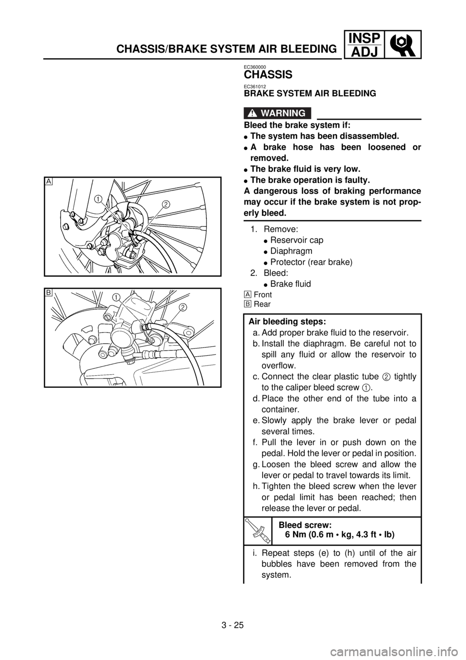
1. Remove:
lReservoir cap
lDiaphragm
lProtector (rear brake)
2. Bleed:
lBrake fluid
Front
õRear
Air bleeding steps:
a. Add proper brake fluid to the reservoir.
b. Install the diaphragm. Be careful not to
spill any fluid or allow the reservoir to
overflow.
c. Connect the clear plastic tube 2 tightly
to the caliper bleed screw 1.
d. Place the other end of the tube into a
container.
e. Slowly apply the brake lever or pedal
several times.
f. Pull the lever in or push down on the
pedal. Hold the lever or pedal in position.
g. Loosen the bleed screw and allow the
lever or pedal to travel towards its limit.
h. Tighten the bleed screw when the lever
or pedal limit has been reached; then
release the lever or pedal.
T R..
Bleed screw:
6 Nm (0.6 m • kg, 4.3 ft • lb)
i. Repeat steps (e) to (h) until of the air
bubbles have been removed from the
system.
õ