YAMAHA YZ426F 2000 Betriebsanleitungen (in German)
Manufacturer: YAMAHA, Model Year: 2000, Model line: YZ426F, Model: YAMAHA YZ426F 2000Pages: 608, PDF-Größe: 45.52 MB
Page 121 of 608
2 - 16
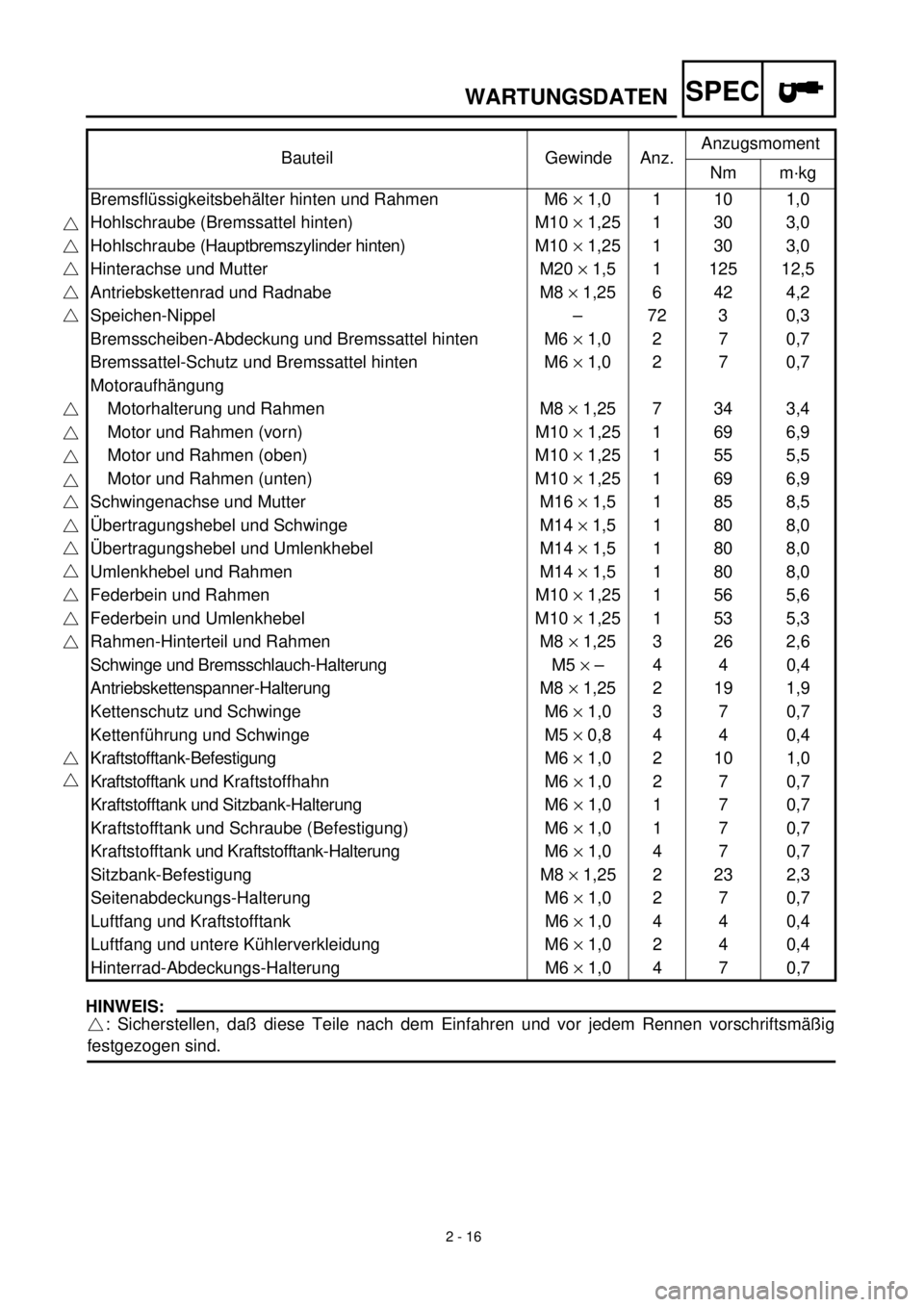
WARTUNGSDATENSPEC
HINWEIS:HINWEIS:
: Sicherstellen, daß diese Teile nach dem Einfahren und vor jedem Rennen vorschriftsmäßig
festgezogen sind.Bauteil Gewinde Anz.Anzugsmoment
Nm m·kg
Bremsflüssigkeitsbehälter hinten und Rahmen M6 ´ 1,0 1 10 1,0
Hohlschraube (Bremssattel hinten) M10 ´ 1,25 1 30 3,0
Hohlschraube (Hauptbremszylinder hinten)M10 ´ 1,25 1 30 3,0
Hinterachse und Mutter M20 ´ 1,5 1 125 12,5
Antriebskettenrad und Radnabe M8 ´ 1,25 6 42 4,2
Speichen-Nippel – 72 3 0,3
Bremsscheiben-Abdeckung und Bremssattel hinten M6 ´ 1,0 2 7 0,7
Bremssattel-Schutz und Bremssattel hinten M6 ´ 1,0 2 7 0,7
Motoraufhängung
Motorhalterung und Rahmen M8 ´ 1,25 7 34 3,4
Motor und Rahmen (vorn) M10 ´ 1,25 1 69 6,9
Motor und Rahmen (oben) M10 ´ 1,25 1 55 5,5
Motor und Rahmen (unten) M10 ´ 1,25 1 69 6,9
Schwingenachse und Mutter M16 ´ 1,5 1 85 8,5
Übertragungshebel und Schwinge M14 ´ 1,5 1 80 8,0
Übertragungshebel und Umlenkhebel M14 ´ 1,5 1 80 8,0
Umlenkhebel und Rahmen M14 ´ 1,5 1 80 8,0
Federbein und Rahmen M10 ´ 1,25 1 56 5,6
Federbein und Umlenkhebel M10 ´ 1,25 1 53 5,3
Rahmen-Hinterteil und Rahmen M8 ´ 1,25 3 26 2,6
Schwinge und Bremsschlauch-Halterung M5 ´ – 4 4 0,4
Antriebskettenspanner-Halterung M8 ´ 1,25 2 19 1,9
Kettenschutz und Schwinge M6 ´ 1,0 3 7 0,7
Kettenführung und Schwinge M5 ´ 0,8 4 4 0,4
Kraftstofftank-Befestigung M6 ´ 1,0 2 10 1,0
Kraftstofftank und Kraftstoffhahn M6 ´ 1,0 2 7 0,7
Kraftstofftank und Sitzbank-Halterung M6 ´ 1,0 1 7 0,7
Kraftstofftank und Schraube (Befestigung) M6 ´ 1,0 1 7 0,7
Kraftstofftank und Kraftstofftank-Halterung M6 ´ 1,0 4 7 0,7
Sitzbank-Befestigung M8 ´ 1,25 2 23 2,3
Seitenabdeckungs-Halterung M6 ´ 1,0 2 7 0,7
Luftfang und Kraftstofftank M6 ´ 1,0 4 4 0,4
Luftfang und untere Kühlerverkleidung M6 ´ 1,0 2 4 0,4
Hinterrad-Abdeckungs-Halterung M6 ´ 1,0 4 7 0,7
Page 122 of 608

2 - 17
WARTUNGSDATENSPEC
ELEKTRISCHE ANLAGE
Bauteil Spezifikation Grenzwert
Zündsystem
Zündversteller elektrisch ----
CDI-Schwungradmagnetzünder
Typ (Hersteller) F5JG (YAMAHA) ----
Widerstand (Farbe) der Erregerspule 1 720–1.080 W bei 20 ˚C
(grün – braun)----
Widerstand (Farbe) der Erregerspule 2 44–66 W bei 20 ˚C
(schwarz – rosa)----
Impulsgeber-Widerstand (Farbe) 248–372 W bei 20 ˚C
(weiß – rot)----
CDI-Zündbox: Typ (Hersteller) 5JG (YAMAHA) ----
Zündspule
Typ (Hersteller) JF2 (YAMAHA) ----
Min. Zündfunkenstrecke 6 mm ----
Primärwicklungs-Widerstand 0,20–0,30 W bei 20 ˚C ----
Sekundärwicklungs-Widerstand 9,5–14,3 kW bei 20 ˚C ----
Bauteil Gewinde Anz.Anzugsmoment
Nm m·kg
Stator M6 ´ 1,0 3 10 1,0
Rotor M10 ´ 1,25 1 48 4,8
Zündspule M6 ´ 1,0 2 7 0,7
Page 123 of 608
SPEC
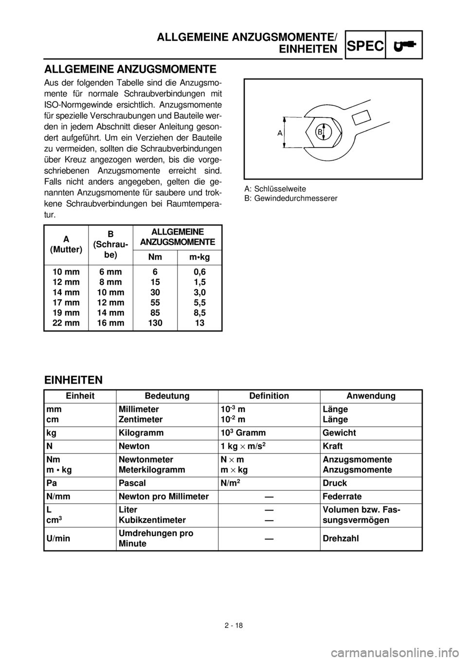
ALLGEMEINE ANZUGSMOMENTE/
EINHEITEN
ALLGEMEINE ANZUGSMOMENTE
Aus der folgenden Tabelle sind die Anzugsmo-
mente für normale Schraubverbindungen mit
ISO-Normgewinde ersichtlich. Anzugsmomente
für spezielle Verschraubungen und Bauteile wer-
den in jedem Abschnitt dieser Anleitung geson-
dert aufgeführt. Um ein Verziehen der Bauteile
zu vermeiden, sollten die Schraubverbindungen
über Kreuz angezogen werden, bis die vorge-
schriebenen Anzugsmomente erreicht sind.
Falls nicht anders angegeben, gelten die ge-
nannten Anzugsmomente für saubere und trok-
kene Schraubverbindungen bei Raumtempera-
tur.
A
(Mutter)B
(Schrau-
be)ALLGEMEINE
ANZUGSMOMENTE
Nm m•kg
10 mm
12 mm
14 mm
17 mm
19 mm
22 mm6 mm
8 mm
10 mm
12 mm
14 mm
16 mm6
15
30
55
85
1300,6
1,5
3,0
5,5
8,5
13
A: Schlüsselweite
B: Gewindedurchmesserer
EINHEITEN
Einheit Bedeutung Definition Anwendung
mm
cmMillimeter
Zentimeter10
-3
m
10
-2
mLänge
Länge
kg Kilogramm 10
3
Gramm Gewicht
N Newton 1 kg
´
m/s
2
Kraft
Nm
m • kgNewtonmeter
MeterkilogrammN
´
m
m
´
kgAnzugsmomente
Anzugsmomente
Pa Pascal N/m
2
Druck
N/mm Newton pro Millimeter — Federrate
L
cm
3
Liter
Kubikzentimeter—
—Volumen bzw. Fas-
sungsvermögen
U/minUmdrehungen pro
Minute— Drehzahl
2 - 18
Page 124 of 608
2 - 19
SPEC
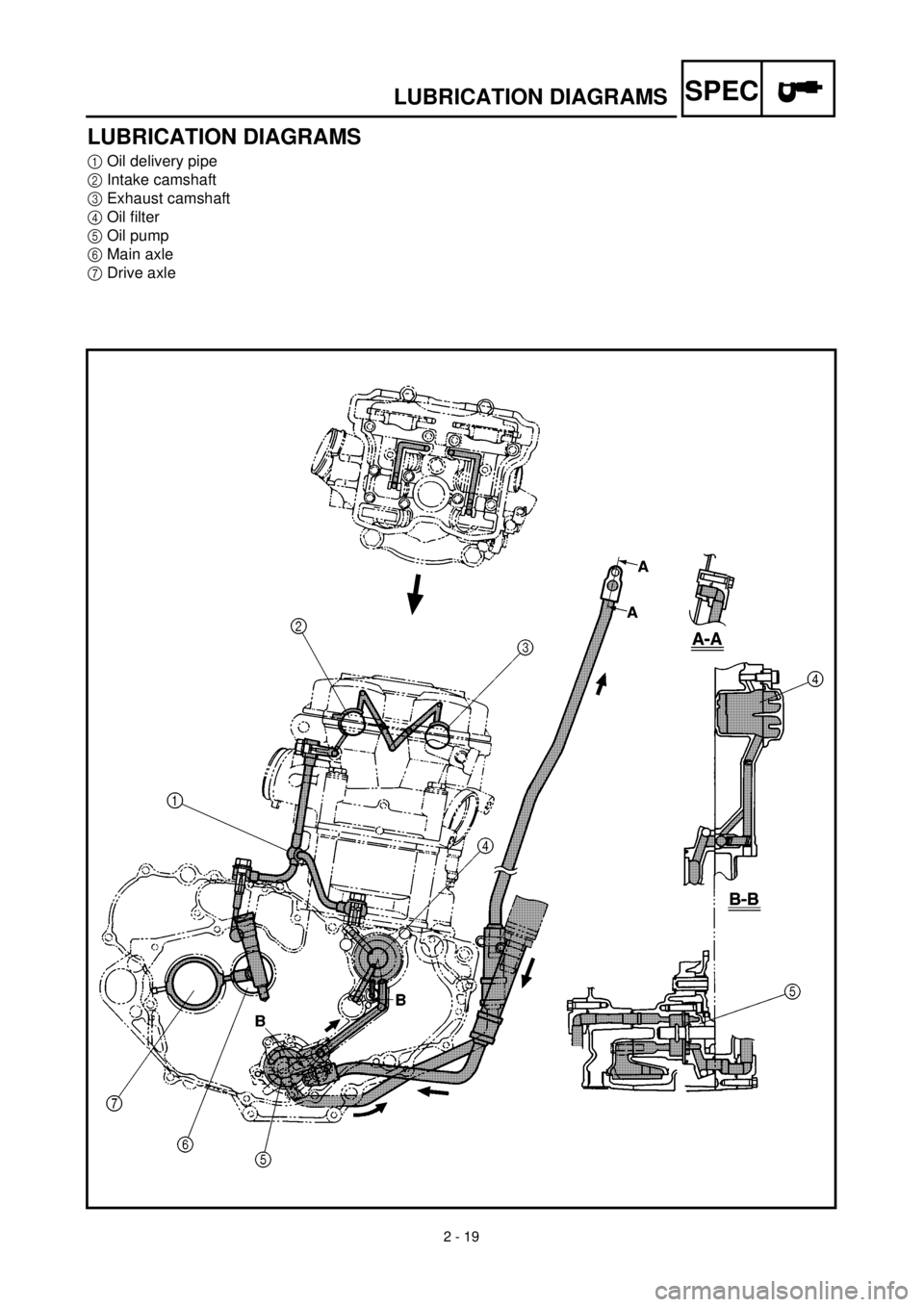
LUBRICATION DIAGRAMS
LUBRICATION DIAGRAMS
1
Oil delivery pipe
2
Intake camshaft
3
Exhaust camshaft
4
Oil filter
5
Oil pump
6
Main axle
7
Drive axle
Page 125 of 608

SPEC
SCHEMAS DE GRAISSAGE
SCHMIERSYSTEM-SCHAUBILDER
SCHMIERSYSTEM-SCHAUBIL-
DER
1
Ölzufuhrleitung
2
Einlaß-Nockenwelle
3
Auslaß-Nockenwelle
4
Ölfilter
5
Ölpumpe
6
Getriebe-Eingangswelle
7
Getriebe-Ausgangswelle
SCHEMAS DE GRAISSAGE
1
Tuyau d’arrivée d’huile
2
Arbre à cames d’admission
3
Arbre à cames d’échappement
4
Filtre à huile
5
Pompe à huile
6
Arbre primaire
7
Arbre secondaire
2 - 19
Page 126 of 608
2 - 20
SPEC
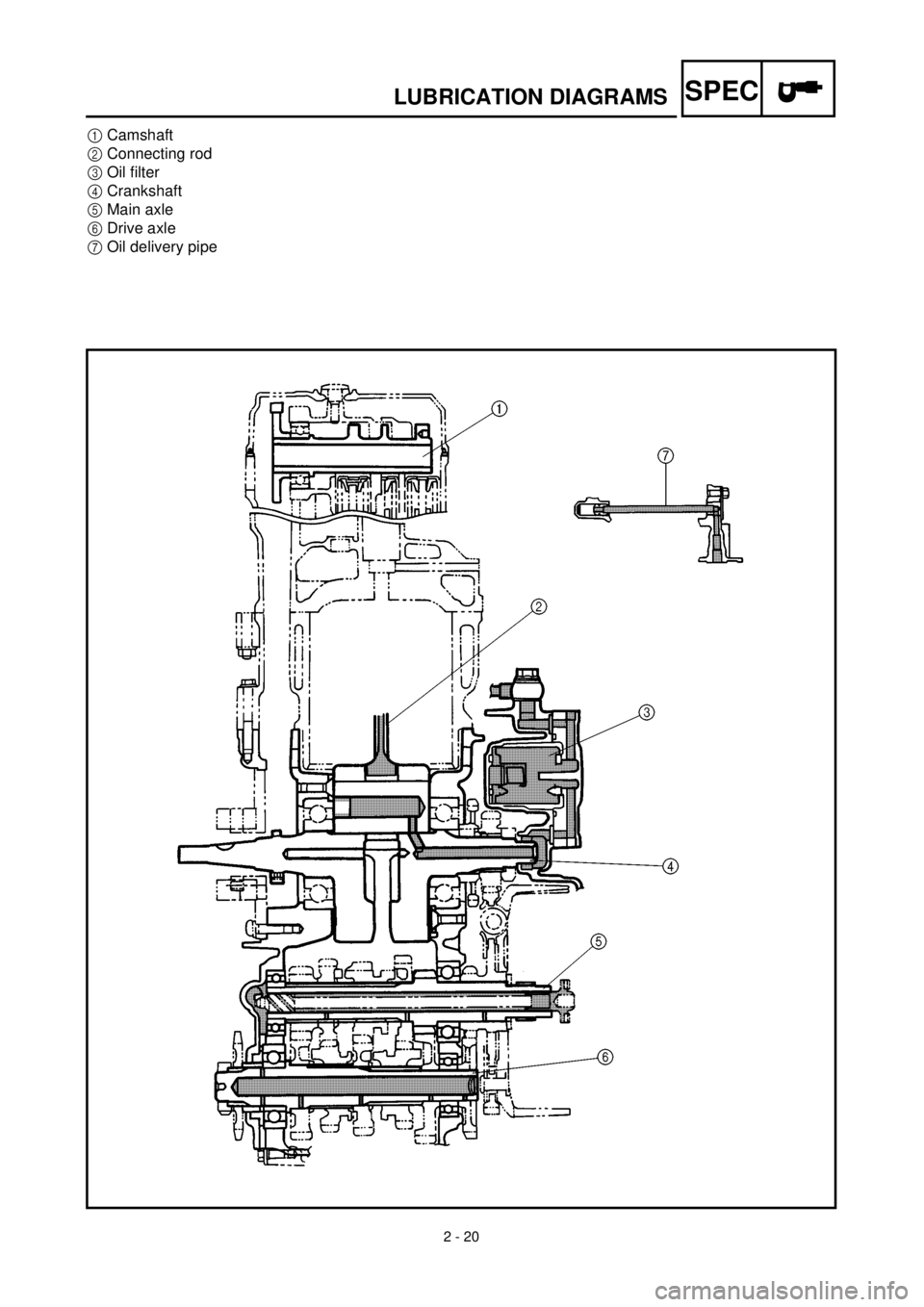
LUBRICATION DIAGRAMS
1
Camshaft
2
Connecting rod
3
Oil filter
4
Crankshaft
5
Main axle
6
Drive axle
7
Oil delivery pipe
Page 127 of 608

SPEC
SCHEMAS DE GRAISSAGE
SCHMIERSYSTEM-SCHAUBILDER
1
Nockenwelle
2
Pleuel
3
Ölfilter
4
Kurbelwelle
5
Getriebe-Eingangswelle
6
Getriebe-Ausgangswelle
7
Ölzufuhrleitung
1
Arbre à cames
2
Bielle
3
Filtre à huile
4
Vilebrequin
5
Arbre primaire
6
Arbre secondaire
7
Tuyau d’arrivée d’huile
2 - 20
Page 128 of 608
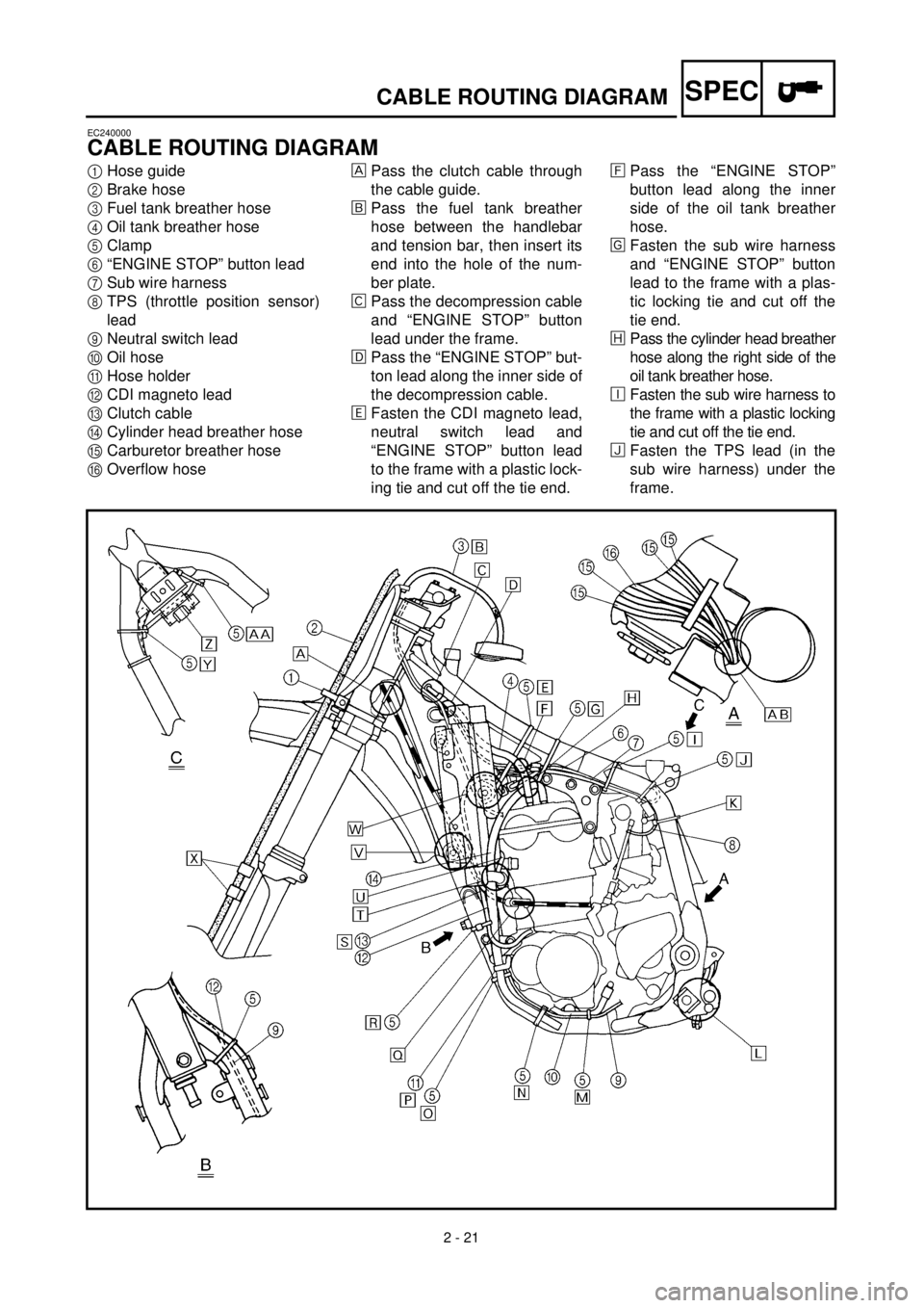
2 - 21
SPEC
CABLE ROUTING DIAGRAM
EC240000
CABLE ROUTING DIAGRAM
1
Hose guide
2
Brake hose
3
Fuel tank breather hose
4
Oil tank breather hose
5
Clamp
6
“ENGINE STOP” button lead
7
Sub wire harness
8
TPS (throttle position sensor)
lead
9
Neutral switch lead
0
Oil hose
A
Hose holder
B
CDI magneto lead
C
Clutch cable
D
Cylinder head breather hose
E
Carburetor breather hose
F
Overflow hose
Pass the clutch cable through
the cable guide.
õ
Pass the fuel tank breather
hose between the handlebar
and tension bar, then insert its
end into the hole of the num-
ber plate.
‚
Pass the decompression cable
and “ENGINE STOP” button
lead under the frame.
ë
Pass the “ENGINE STOP” but-
ton lead along the inner side of
the decompression cable.
ä
Fasten the CDI magneto lead,
neutral switch lead and
“ENGINE STOP” button lead
to the frame with a plastic lock-
ing tie and cut off the tie end.
ì
Pass the “ENGINE STOP”
button lead along the inner
side of the oil tank breather
hose.
í
Fasten the sub wire harness
and “ENGINE STOP” button
lead to the frame with a plas-
tic locking tie and cut off the
tie end.
î
Pass the cylinder head breather
hose along the right side of the
oil tank breather hose.
é
Fasten the sub wire harness to
the frame with a plastic locking
tie and cut off the tie end.
ï
Fasten the TPS lead (in the
sub wire harness) under the
frame.
Page 129 of 608

SPEC
CHEMINEMENT DES CABLES
KABELFÜHRUNG
KABELFÜHRUNG
1
Kabelführung
2
Bremsschlauch
3
Kraftstofftank-Belüftungsschlauch
4
Öltank-Belüftungsschlauch
5Kabelbinder
6Motorstoppschalter-Kabel
7Nebenkabelsatz
8Drosselklappen-Positionssensor (TPS)
9Leerlaufschalter-Kabel
0Ölschlauch
ASchlauchhalterung
BCDI-Schwungradmagnetzünder-Kabel
CKupplungszug
DZylinderkopf-Entlüftungsschlauch
EVergaser-Entlüftungsschlauch
FAuslaufschutzschlauch
Den Kupplungszug durch die Kabelführung füh-
ren.
õDen Kraftstofftank-Belüftungsschlauch zwischen
Lenker und Zugstrebe führen und das Ende
durch die Bohrung im Nummerschild führen.
‚Den Dekompressionszug und das Motorstopp-
schalterkabel unter dem Rahmen hindurchfüh-
ren.
ëDas Motorstoppschalter-Kabel hinter dem De-
kompressionszug führen.
äDas CDI-Schwungrad-Magnetzünderkabel, Leer-
laufschalterkabel und Motorstoppschalterkabel
mit einem Einweg-Kabelbinder am Rahmen be-
festigen und das überstehende Ende des Kabel-
binders abschneiden.
ìDas Motorstoppschalter-Kabel hinter dem Öl-
tank-Belüftungsschlauch führen.
íDen Nebenkabelbaum und Motorstoppschalter-
kabel mit einem Einweg-Kabelbinder am Rah-
men befestigen und das überstehende Ende des
Kabelbinders abschneiden.
îDen Zylinderkopf-Entlüftungsschlauch rechts
vom Öltank-Belüftungsschlauch führen.
éDen Nebenkabelbaum mit einem Einweg-Kabel-
binder am Rahmen befestigen und das überste-
hende Ende des Kabelbinders abschneiden.
ïDas TPS-Kabel (im Nebenkabelbaum) unter
dem Rahmen befestigen.
CHEMINEMENT DES CABLES
1Guide de flexible
2Tuyau de frein
3Reniflard de réservoir d’essence
4Reniflard de réservoir d’huile
5Bride
6Fil de bouton d’arrêt du moteur “ENGINE STOP”
7Faisceau de fils secondaires
8Fil de TPS (copteur du papillon d’accélération)
9Fil de contacteur de point mort
0Flexible d’huile
ASupport de flexible
BFil de magnéto CDI
CCâble d’embrayage
DReniflard de culasse
EReniflard de carburateur
FFlexible de trop-plein
Faire passer le câble d’embrayage dans le guide de
câble.
õFaire passer le reniflard du réservoir d’essence entre
le guidon et la barre de tension, puis insérer son
extrémité dans l’orifice prévu sur la plaque de
numéro.
‚Faire passer le câble de décompression et le fil de
bouton d’arrêt du moteur “ENGINE STOP” sous le
cadre.
ëFaire passer le fil de bouton d’arrêt du moteur
“ENGINE STOP” derrière le câble de décompres-
sion.
äAttacher le fil de magnéto CDI, le fil de contacteur de
point mort et le fil de bouton d’arrêt du moteur
“ENGINE STOP” au cadre à l’aide d’une attache en
plastique et couper l’extrémité de l’attache.
ìFaire passer le fil de bouton d’arrêt du moteur
“ENGINE STOP” derrière le reniflard du réservoir
d’huile et couper l’extrémité de l’attache.
íAttacher le faisceau de fils secondaires et le fil de
bouton d’arrêt du moteur “ENGINE STOP” au cadre
à l’aide d’une attache en plastique et couper l’extré-
mité de l’attache.
îFaire passer le reniflard de culasse le long du côté
droit du reniflard du réservoir d’huile.
éAttacher le faisceau de fils secondaires au cadre à
l’aide d’une attache en plastique et couper l’extrémité
de l’attache.
ïAttacher le fil de TPS (dans le faisceau de fils secon-
daires) sous le cadre.
2 - 21
Page 130 of 608
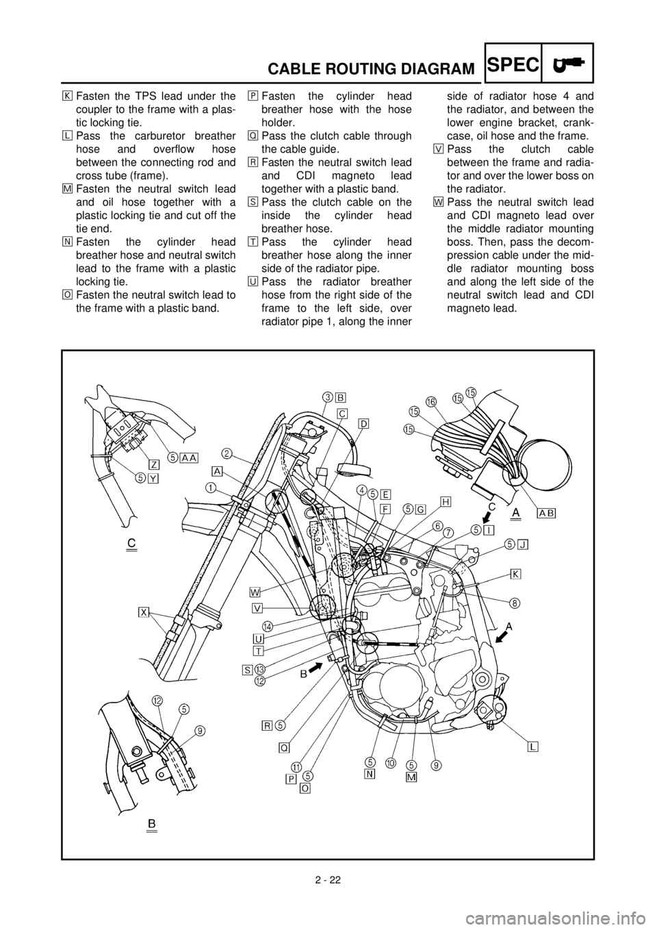
2 - 22
SPEC
CABLE ROUTING DIAGRAM
ð
Fasten the TPS lead under the
coupler to the frame with a plas-
tic locking tie.
ñPass the carburetor breather
hose and overflow hose
between the connecting rod and
cross tube (frame).
÷Fasten the neutral switch lead
and oil hose together with a
plastic locking tie and cut off the
tie end.
öFasten the cylinder head
breather hose and neutral switch
lead to the frame with a plastic
locking tie.
¯Fasten the neutral switch lead to
the frame with a plastic band.¸Fasten the cylinder head
breather hose with the hose
holder.
ÎPass the clutch cable through
the cable guide.
åFasten the neutral switch lead
and CDI magneto lead
together with a plastic band.
êPass the clutch cable on the
inside the cylinder head
breather hose.
æPass the cylinder head
breather hose along the inner
side of the radiator pipe.
èPass the radiator breather
hose from the right side of the
frame to the left side, over
radiator pipe 1, along the innerside of radiator hose 4 and
the radiator, and between the
lower engine bracket, crank-
case, oil hose and the frame.
×Pass the clutch cable
between the frame and radia-
tor and over the lower boss on
the radiator.
ãPass the neutral switch lead
and CDI magneto lead over
the middle radiator mounting
boss. Then, pass the decom-
pression cable under the mid-
dle radiator mounting boss
and along the left side of the
neutral switch lead and CDI
magneto lead.