YAMAHA YZ426F 2002 Betriebsanleitungen (in German)
Manufacturer: YAMAHA, Model Year: 2002, Model line: YZ426F, Model: YAMAHA YZ426F 2002Pages: 633, PDF-Größe: 36.22 MB
Page 131 of 633
SPEC
2 - 20
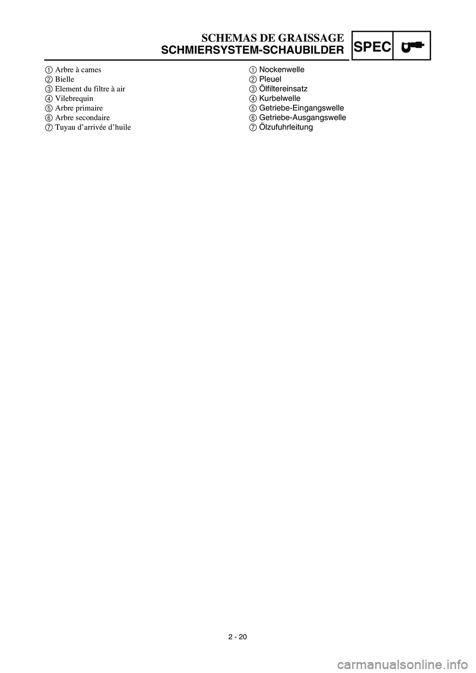
SCHEMAS DE GRAISSAGE
SCHMIERSYSTEM-SCHAUBILDER
1
Nockenwelle
2
Pleuel
3
Ölfiltereinsatz
4
Kurbelwelle
5
Getriebe-Eingangswelle
6
Getriebe-Ausgangswelle
7
Ölzufuhrleitung
1
Arbre à cames
2
Bielle
3
Element du filtre à air
4
Vilebrequin
5
Arbre primaire
6
Arbre secondaire
7
Tuyau d’arrivée d’huile
Page 132 of 633

2 - 21
SPEC
CABLE ROUTING DIAGRAM
EC240000
CABLE ROUTING DIAGRAM
1
Hose guide
2
Brake hose
3
Fuel tank breather hose
4
Oil tank breather hose
5
Clamp
6
Sub wire harness
7
TPS (throttle position
sensor) lead
8
Neutral switch lead
9
Oil hose
0
Hose holder
A
CDI magneto lead
B
Clutch cable
C
Cylinder head breather hose
D
Carburetor breather hose
E
Overflow hose
Å
Pass the clutch cable through
the cable guide.
ı
Pass the fuel tank breather hose
between the handlebar and ten-
sion bar, then insert its end into
the hole of the number plate.
Ç
Pass the decompression cable
under the oil tank breather pipe.
Î
Fasten the CDI magneto lead
and neutral switch lead to the
frame with a plastic locking tie
and cut off the tie end.
‰
Fasten the sub wire harness to
the frame at the white tape for
the sub wire harness with a
plastic locking tie and cut off the
tie end.
Ï
Pass the cylinder head breather
hose along the right side of the
oil tank breather hose.
Ì
Fasten the sub wire harness to
the frame with a plastic locking
tie ends at the lower left of the
frame and cut off the tie end. For
fastening, pass the plastic lock-
ing tie through the upper holes
in the engine brackets.
Ó
Pass the sub wire harness
between the engine brackets.
Page 133 of 633

SPEC
2 - 21
CHEMINEMENT DES CABLES
KABELFÜHRUNG
KABELFÜHRUNG
1
Kabelführung
2
Bremsschlauch
3
Kraftstofftank-Belüftungsschlauch
4
Öltank-Belüftungsschlauch
5
Kabelbinder
6
Nebenkabelsatz
7
Drosselklappen-Positionssensor (TPS)
8
Leerlaufschalter-Kabel
9
Ölschlauch
0
Schlauchhalterung
A
CDI-Schwungradmagnetzünder-Kabel
B
Kupplungszug
C
Zylinderkopf-Entlüftungsschlauch
D
Vergaser-Entlüftungsschlauch
E
Auslaufschutzschlauch
ÅDen Kupplungszug durch die Kabelführung füh-
ren.
ıDen Kraftstofftank-Belüftungsschlauch zwischen
Lenker und Zugstrebe führen und das Ende
durch die Bohrung im Nummerschild führen.
ÇDen Dekompressionsseilzug unter der Öltank-
Lüftungsleitung verlegen.
ÎDas CDI-Magnetzünderkabel und Leerlaufschal-
terkabel am Rahmen mit einem Einweg-Kabel-
binder befestigen und das überstehende Ende
des Kabelbinders abschneiden.
‰Den Nebenkabelbaum am Rahmen am weißen
Band für den Nebenkabelbaum mit einem Ein-
weg-Kabelbinder befestigen und das überste-
hende Ende des Kabelbinders abschneiden.
ÏDen Zylinderkopf-Entlüftungsschlauch rechts
vom Öltank-Belüftungsschlauch führen.
ÌDen Nebenkabelbaum am Rahmen mit mehrf.
verwendb.-Kabelbinder unten links am Rahmen
befestigen und das überstehende Ende des Ka-
belbinders abschneiden. Zum Befestigen den
Einweg-Kabelbinder durch die oberen Löcher in
den Motorbügeln führen.
ÓDen Nebenkabelsatz zwischen den Motorlagern
hindurchführen.
CHEMINEMENT DES CABLES
1Guide de flexible
2Tuyau de frein
3Reniflard de réservoir d’essence
4Reniflard de réservoir d’huile
5Bride
6Faisceau de fils secondaires
7Fil de TPS (copteur du papillon d’accélération)
8Fil de contacteur de point mort
9Flexible d’huile
0Support de flexible
AFil de magnéto CDI
BCâble d’embrayage
CReniflard de culasse
DReniflard de carburateur
EFlexible de trop-plein
ÅFaire passer le câble d’embrayage dans le guide de
câble.
ıFaire passer le reniflard du réservoir d’essence entre
le guidon et la barre de tension, puis insérer son
extrémité dans l’orifice prévu sur la plaque de
numéro.
ÇFaire passer le câble de décompression sous le reni-
flard du réservoir d’huile.
ÎAttacher le fil de magnéto CDIet le fil de contacteur
de point mort au cadre à l’aide d’une attache en plas-
tique et couper l’extrémité de l’attache.
‰Attacher le faisceau de fils secondaire au cadre à
l’endroit du repère adhésif blanc à l’aide d’une atta-
che en plastique et couper l’extrémité de l’attache.
ÏFaire passer le reniflard de culasse le long du côté
droit du reniflard du réservoir d’huile.
ÌAttacher le faisceau de fil secondaire au cadre à l’aide
d’une attache en plastique en plaçant son extrémité
vers la partie inférieure gauche du cadre et couper
l’extrémité de l’attache. Pour l’attacher, faire passer
l’attache en plastique à travers les orifices supérieurs
des supports de moteur.
ÓFaire passer le faisceau de fils secondaire par les sup-
ports du moteur.
Page 134 of 633

2 - 22
SPEC
CABLE ROUTING DIAGRAM
È
Fasten the TPS lead (in the
sub wire harness) under the
frame so that it does not con-
tact the carburetor.
Ô
Make sure that the TPS lead
coupler does not go outside the
chassis.
Fasten the TPS lead under the
coupler to the frame with a
plastic locking tie.
Ò
Pass the carburetor breather
hose and overflow hose
between the connecting rod
and cross tube (frame).
˜Fasten the neutral switch lead
and oil hose together with a
plastic locking tie and cut off
the tie end.ˆFasten the cylinder head
breather hose with the hose
holder.
ØFasten the neutral switch lead
to the frame with a plastic band
ends toward the rear of the
frame.
∏Fasten the cylinder head
breather hose with the hose
holder.
ŒPass the clutch cable through
the cable guide.
ÂFasten the neutral switch lead
and CDI magneto lead together
with a plastic band.
ÍPass the clutch cable on the
inside the cylinder head
breather hose.ÊPass the cylinder head
breather hose along the inner
side of the radiator pipe.
ËPass the radiator breather
hose from the right side of the
frame to the left side, over radi-
ator pipe 1, along the inner side
of radiator hose 4 and the radi-
ator, and between the lower
engine bracket, crankcase, oil
hose and the frame.
◊Pass the clutch cable between
the frame and radiator and
over the lower boss on the radi-
ator.
Page 135 of 633
SPEC
2 - 22
CHEMINEMENT DES CABLES
KABELFÜHRUNG
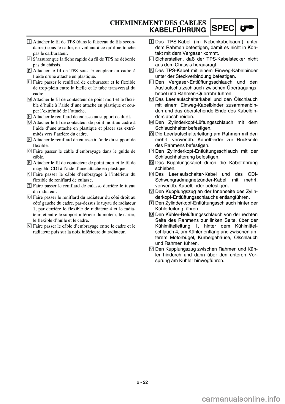
ÈDas TPS-Kabel (im Nebenkabelbaum) unter
dem Rahmen befestigen, damit es nicht in Kon-
takt mit dem Vergaser kommt.
ÔSicherstellen, daß der TPS-Kabelstecker nicht
aus dem Chassis herausragt.
Das TPS-Kabel mit einem Einweg-Kabelbinder
unter der Steckverbindung befestigen.
ÒDen Vergaser-Entlüftungsschlauch und den
Auslaufschutzschlauch zwischen Übertragungs-
hebel und Rahmen-Querrohr führen.
˜Das Leerlaufschalterkabel und den Ölschlauch
mit einem Einweg-Kabelbinder zusammenbin-
den und das überstehende Ende des Kabelbin-
ders abschneiden.
ˆDen Zylinderkopf-Lüftungsschlauch mit dem
Schlauchhalter befestigen.
ØDie Leerlaufschalterleitung am Rahmen mit den
mehrf. verwendb. Kabelbinder zur Rückseite
des Rahmens befestigen.
∏Den Zylinderkopf-Entlüftungsschlauch mit der
Schlauchhalterung befestigen.
ŒDas Kupplungskabel durch die Kabelführung
schieben.
ÂDas Leerlaufschalter-Kabel und das CDI-
Schwungradmagnetzünder-Kabel mit mehrf.
verwendb. Kabelbinder befestigen.
ÍDen Kupplungszug an der Innenseite des Zylin-
derkopf-Entlüftungsschlauchs entlangführen.
ÊDen Zylinderkopf-Entlüftungsschlauch hinter der
Kühlerleitung führen.
ËDen Kühler-Belüftungsschlauch von der rechten
Seite des Rahmens zur linken Seite, über der
Kühlmittelleitung 1, hinter dem Kühlmittel-
schlauch 4, am Kühler entlang und zwischen un-
terem Motorbügel, Kurbelgehäuse, Ölschlauch
und Rahmen führen.
◊Den Kupplungszug zwischen Rahmen und Küh-
ler hindurch und dann über den unteren Vor-
sprung am Kühler hinwegführen. ÈAttacher le fil de TPS (dans le faisceau de fils secon-
daires) sous le cadre, en veillant à ce qu’il ne touche
pas le carburateur.
ÔS’assurer que la fiche rapide du fil de TPS ne déborde
pas du châssis.
Attacher le fil de TPS sous le coupleur au cadre à
l’aide d’une attache en plastique.
ÒFaire passer le reniflard de carburateur et le flexible
de trop-plein entre la bielle et le tube transversal du
cadre.
˜Attacher le fil de contacteur de point mort et le flexi-
ble d’huile à l’aide d’une attache en plastique et cou-
per l’extrémité de l’attache.
ˆAttacher le reniflard de culasse au support de durit.
ØAttacher le fil de contacteur de point mort au cadre à
l’aide d’une attache en plastique et placer ses extré-
mités vers l’arrière du cadre.
∏Attacher le reniflard de culasse à l’aide du support de
flexible.
ŒFaire passer le câble d’embrayage dans le guide de
câble.
ÂAttacher le fil de contacteur de point mort et le fil de
magnéto CDI à l’aide d’une attache en plastique.
ÍFaire passer le câble d’embrayage à l’intérieur du
flexible de reniflard de culasse.
ÊFaire passer le reniflard de culasse derrière le tuyau
du radiateur.
ËFaire passer le reniflard du radiateur du côté droit au
côté gauche du cadre, par-dessus le tuyau de radiateur
1, par derrière le flexible de radiateur 4 et le radia-
teur, et entre le support inférieur du moteur, le carter,
le flexible d’huile et le cadre.
◊Faire passer le câble d’embrayage entre le cadre et le
radiateur puis sur la noix inférieure du radiateur.
Page 136 of 633
2 - 23
SPEC
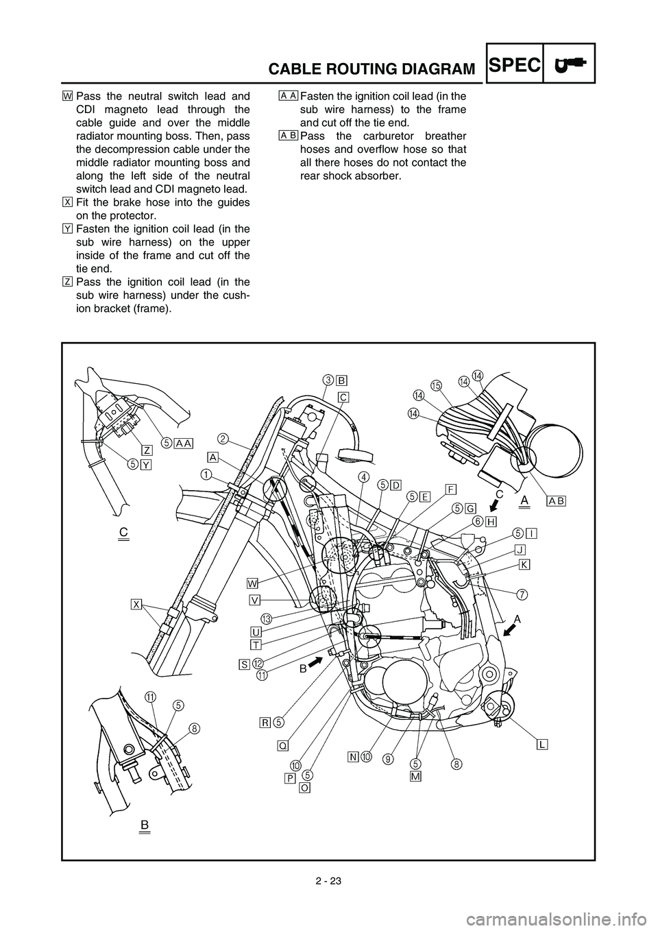
„Pass the neutral switch lead and
CDI magneto lead through the
cable guide and over the middle
radiator mounting boss. Then, pass
the decompression cable under the
middle radiator mounting boss and
along the left side of the neutral
switch lead and CDI magneto lead.
ÙFit the brake hose into the guides
on the protector.
ÁFasten the ignition coil lead (in the
sub wire harness) on the upper
inside of the frame and cut off the
tie end.
ÛPass the ignition coil lead (in the
sub wire harness) under the cush-
ion bracket (frame).Fasten the ignition coil lead (in the
sub wire harness) to the frame
and cut off the tie end.
Pass the carburetor breather
hoses and overflow hose so that
all there hoses do not contact the
rear shock absorber.AA
AB
CABLE ROUTING DIAGRAM
Page 137 of 633
SPEC
2 - 23
CHEMINEMENT DES CABLES
KABELFÜHRUNG
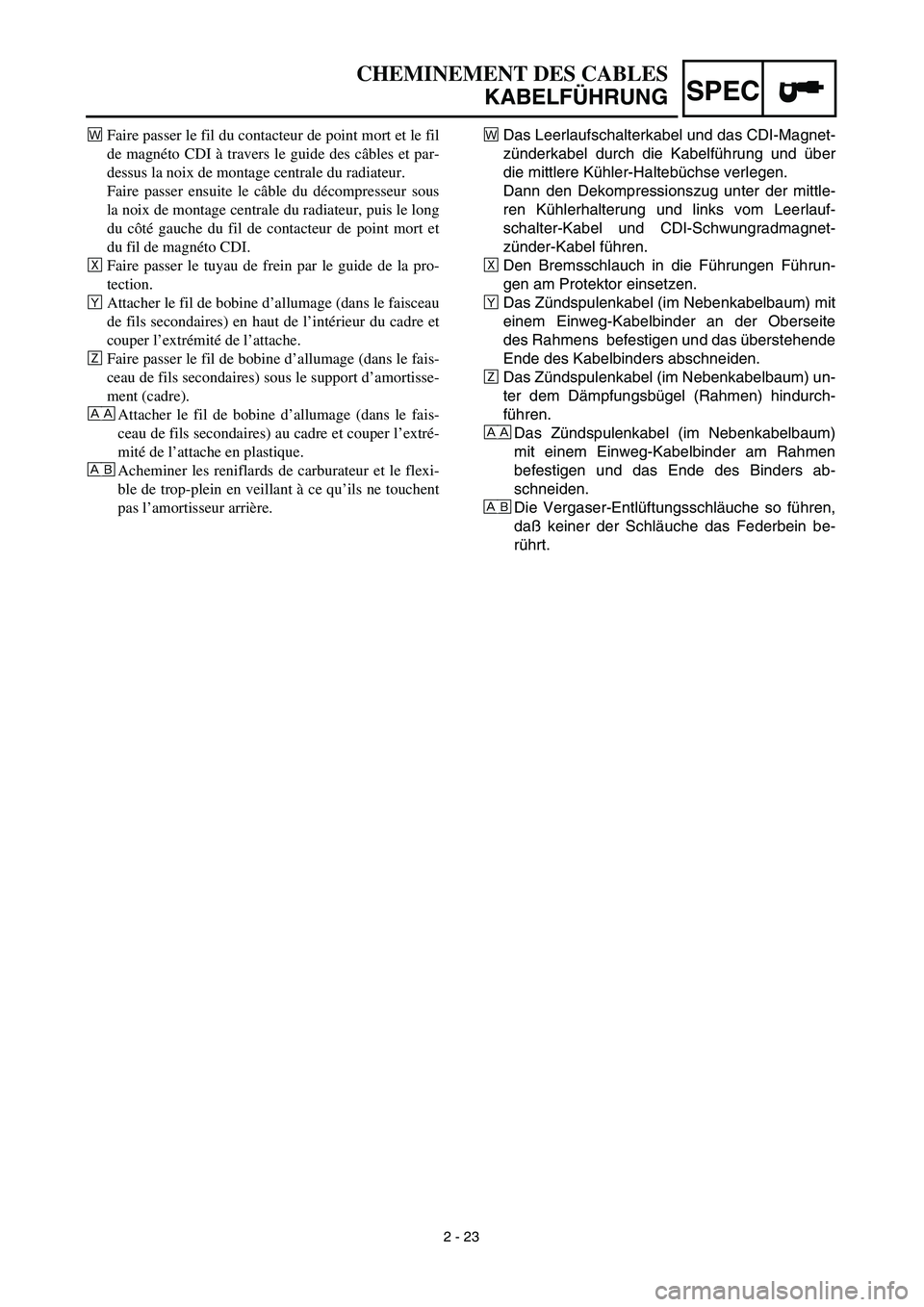
„Das Leerlaufschalterkabel und das CDI-Magnet-
zünderkabel durch die Kabelführung und über
die mittlere Kühler-Haltebüchse verlegen.
Dann den Dekompressionszug unter der mittle-
ren Kühlerhalterung und links vom Leerlauf-
schalter-Kabel und CDI-Schwungradmagnet-
zünder-Kabel führen.
ÙDen Bremsschlauch in die Führungen Führun-
gen am Protektor einsetzen.
ÁDas Zündspulenkabel (im Nebenkabelbaum) mit
einem Einweg-Kabelbinder an der Oberseite
des Rahmens befestigen und das überstehende
Ende des Kabelbinders abschneiden.
ÛDas Zündspulenkabel (im Nebenkabelbaum) un-
ter dem Dämpfungsbügel (Rahmen) hindurch-
führen.
Das Zündspulenkabel (im Nebenkabelbaum)
mit einem Einweg-Kabelbinder am Rahmen
befestigen und das Ende des Binders ab-
schneiden.
Die Vergaser-Entlüftungsschläuche so führen,
daß keiner der Schläuche das Federbein be-
rührt. ÅÅ
Åı
„Faire passer le fil du contacteur de point mort et le fil
de magnéto CDI à travers le guide des câbles et par-
dessus la noix de montage centrale du radiateur.
Faire passer ensuite le câble du décompresseur sous
la noix de montage centrale du radiateur, puis le long
du côté gauche du fil de contacteur de point mort et
du fil de magnéto CDI.
ÙFaire passer le tuyau de frein par le guide de la pro-
tection.
ÁAttacher le fil de bobine d’allumage (dans le faisceau
de fils secondaires) en haut de l’intérieur du cadre et
couper l’extrémité de l’attache.
ÛFaire passer le fil de bobine d’allumage (dans le fais-
ceau de fils secondaires) sous le support d’amortisse-
ment (cadre).
Attacher le fil de bobine d’allumage (dans le fais-
ceau de fils secondaires) au cadre et couper l’extré-
mité de l’attache en plastique.
Acheminer les reniflards de carburateur et le flexi-
ble de trop-plein en veillant à ce qu’ils ne touchent
pas l’amortisseur arrière. ÅÅ
Åı
Page 138 of 633
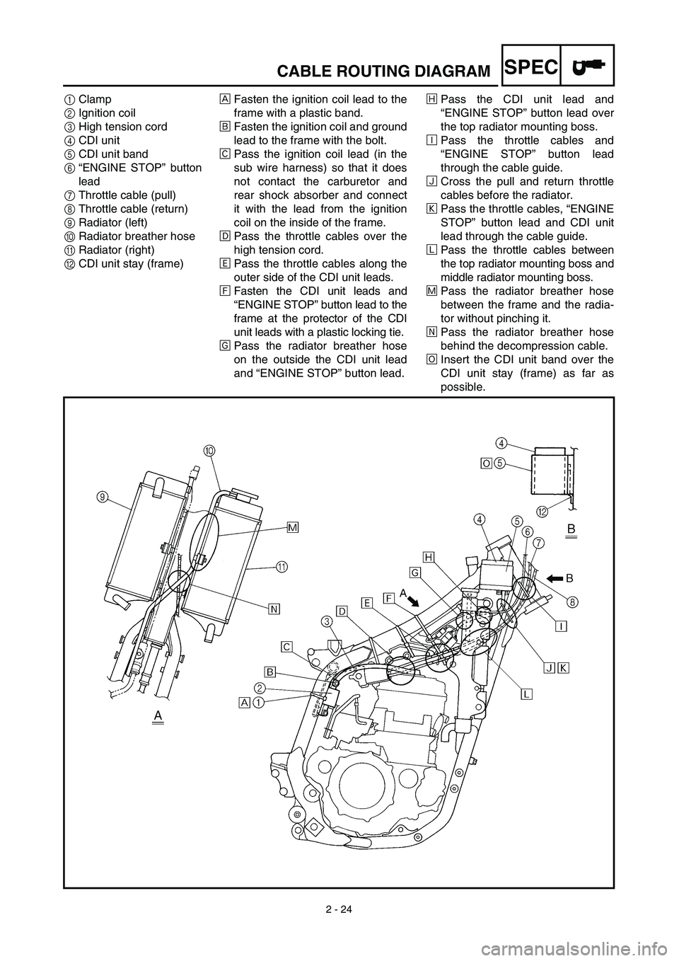
2 - 24
SPECCABLE ROUTING DIAGRAM
1Clamp
2Ignition coil
3High tension cord
4CDI unit
5CDI unit band
6“ENGINE STOP” button
lead
7Throttle cable (pull)
8Throttle cable (return)
9Radiator (left)
0Radiator breather hose
ARadiator (right)
BCDI unit stay (frame)ÅFasten the ignition coil lead to the
frame with a plastic band.
ıFasten the ignition coil and ground
lead to the frame with the bolt.
ÇPass the ignition coil lead (in the
sub wire harness) so that it does
not contact the carburetor and
rear shock absorber and connect
it with the lead from the ignition
coil on the inside of the frame.
ÎPass the throttle cables over the
high tension cord.
‰Pass the throttle cables along the
outer side of the CDI unit leads.
ÏFasten the CDI unit leads and
“ENGINE STOP” button lead to the
frame at the protector of the CDI
unit leads with a plastic locking tie.
ÌPass the radiator breather hose
on the outside the CDI unit lead
and “ENGINE STOP” button lead.ÓPass the CDI unit lead and
“ENGINE STOP” button lead over
the top radiator mounting boss.
ÈPass the throttle cables and
“ENGINE STOP” button lead
through the cable guide.
ÔCross the pull and return throttle
cables before the radiator.
Pass the throttle cables, “ENGINE
STOP” button lead and CDI unit
lead through the cable guide.
ÒPass the throttle cables between
the top radiator mounting boss and
middle radiator mounting boss.
˜Pass the radiator breather hose
between the frame and the radia-
tor without pinching it.
ˆPass the radiator breather hose
behind the decompression cable.
ØInsert the CDI unit band over the
CDI unit stay (frame) as far as
possible.
Page 139 of 633
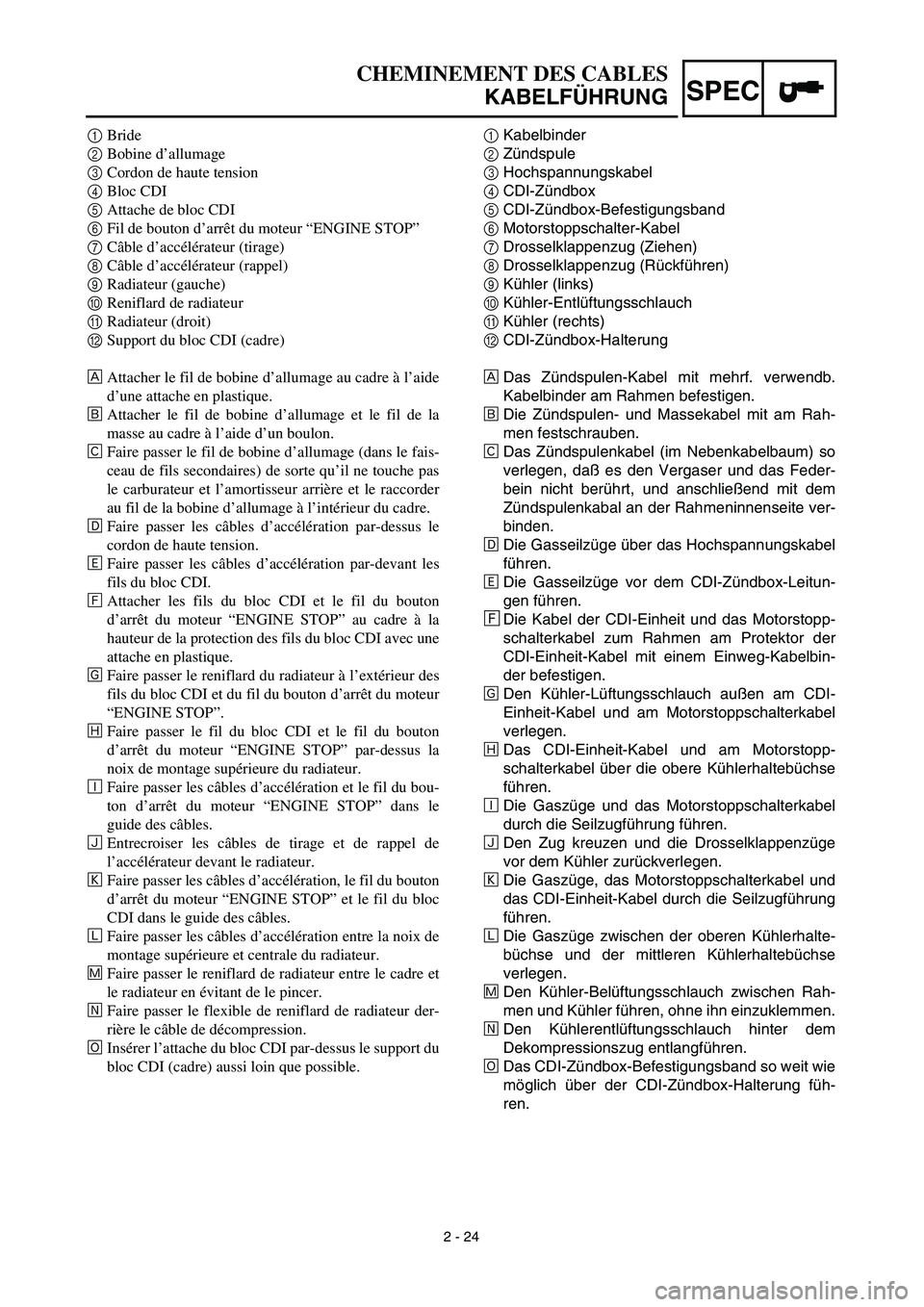
SPEC
2 - 24
CHEMINEMENT DES CABLES
KABELFÜHRUNG
1Kabelbinder
2Zündspule
3Hochspannungskabel
4CDI-Zündbox
5CDI-Zündbox-Befestigungsband
6Motorstoppschalter-Kabel
7Drosselklappenzug (Ziehen)
8Drosselklappenzug (Rückführen)
9Kühler (links)
0Kühler-Entlüftungsschlauch
AKühler (rechts)
BCDI-Zündbox-Halterung
ÅDas Zündspulen-Kabel mit mehrf. verwendb.
Kabelbinder am Rahmen befestigen.
ıDie Zündspulen- und Massekabel mit am Rah-
men festschrauben.
ÇDas Zündspulenkabel (im Nebenkabelbaum) so
verlegen, daß es den Vergaser und das Feder-
bein nicht berührt, und anschließend mit dem
Zündspulenkabal an der Rahmeninnenseite ver-
binden.
ÎDie Gasseilzüge über das Hochspannungskabel
führen.
‰Die Gasseilzüge vor dem CDI-Zündbox-Leitun-
gen führen.
ÏDie Kabel der CDI-Einheit und das Motorstopp-
schalterkabel zum Rahmen am Protektor der
CDI-Einheit-Kabel mit einem Einweg-Kabelbin-
der befestigen.
ÌDen Kühler-Lüftungsschlauch außen am CDI-
Einheit-Kabel und am Motorstoppschalterkabel
verlegen.
ÓDas CDI-Einheit-Kabel und am Motorstopp-
schalterkabel über die obere Kühlerhaltebüchse
führen.
ÈDie Gaszüge und das Motorstoppschalterkabel
durch die Seilzugführung führen.
ÔDen Zug kreuzen und die Drosselklappenzüge
vor dem Kühler zurückverlegen.
Die Gaszüge, das Motorstoppschalterkabel und
das CDI-Einheit-Kabel durch die Seilzugführung
führen.
ÒDie Gaszüge zwischen der oberen Kühlerhalte-
büchse und der mittleren Kühlerhaltebüchse
verlegen.
˜Den Kühler-Belüftungsschlauch zwischen Rah-
men und Kühler führen, ohne ihn einzuklemmen.
ˆDen Kühlerentlüftungsschlauch hinter dem
Dekompressionszug entlangführen.
ØDas CDI-Zündbox-Befestigungsband so weit wie
möglich über der CDI-Zündbox-Halterung füh-
ren. 1Bride
2Bobine d’allumage
3Cordon de haute tension
4Bloc CDI
5Attache de bloc CDI
6Fil de bouton d’arrêt du moteur “ENGINE STOP”
7Câble d’accélérateur (tirage)
8Câble d’accélérateur (rappel)
9Radiateur (gauche)
0Reniflard de radiateur
ARadiateur (droit)
BSupport du bloc CDI (cadre)
ÅAttacher le fil de bobine d’allumage au cadre à l’aide
d’une attache en plastique.
ıAttacher le fil de bobine d’allumage et le fil de la
masse au cadre à l’aide d’un boulon.
ÇFaire passer le fil de bobine d’allumage (dans le fais-
ceau de fils secondaires) de sorte qu’il ne touche pas
le carburateur et l’amortisseur arrière et le raccorder
au fil de la bobine d’allumage à l’intérieur du cadre.
ÎFaire passer les câbles d’accélération par-dessus le
cordon de haute tension.
‰Faire passer les câbles d’accélération par-devant les
fils du bloc CDI.
ÏAttacher les fils du bloc CDI et le fil du bouton
d’arrêt du moteur “ENGINE STOP” au cadre à la
hauteur de la protection des fils du bloc CDI avec une
attache en plastique.
ÌFaire passer le reniflard du radiateur à l’extérieur des
fils du bloc CDI et du fil du bouton d’arrêt du moteur
“ENGINE STOP”.
ÓFaire passer le fil du bloc CDI et le fil du bouton
d’arrêt du moteur “ENGINE STOP” par-dessus la
noix de montage supérieure du radiateur.
ÈFaire passer les câbles d’accélération et le fil du bou-
ton d’arrêt du moteur “ENGINE STOP” dans le
guide des câbles.
ÔEntrecroiser les câbles de tirage et de rappel de
l’accélérateur devant le radiateur.
Faire passer les câbles d’accélération, le fil du bouton
d’arrêt du moteur “ENGINE STOP” et le fil du bloc
CDI dans le guide des câbles.
ÒFaire passer les câbles d’accélération entre la noix de
montage supérieure et centrale du radiateur.
˜Faire passer le reniflard de radiateur entre le cadre et
le radiateur en évitant de le pincer.
ˆFaire passer le flexible de reniflard de radiateur der-
rière le câble de décompression.
ØInsérer l’attache du bloc CDI par-dessus le support du
bloc CDI (cadre) aussi loin que possible.
Page 140 of 633
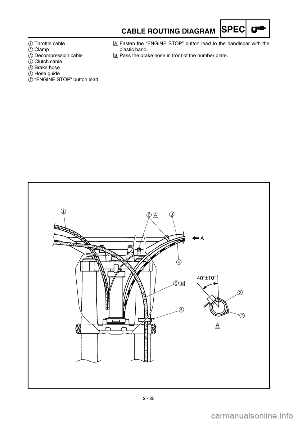
2 - 25
SPECCABLE ROUTING DIAGRAM
1Throttle cable
2Clamp
3Decompression cable
4Clutch cable
5Brake hose
6Hose guide
7“ENGINE STOP” button leadÅFasten the “ENGINE STOP” button lead to the handlebar with the
plastic band.
ıPass the brake hose in front of the number plate.