ECU ACURA NSX 1997 Service Owner's Manual
[x] Cancel search | Manufacturer: ACURA, Model Year: 1997, Model line: NSX, Model: ACURA NSX 1997Pages: 1503, PDF Size: 57.08 MB
Page 523 of 1503
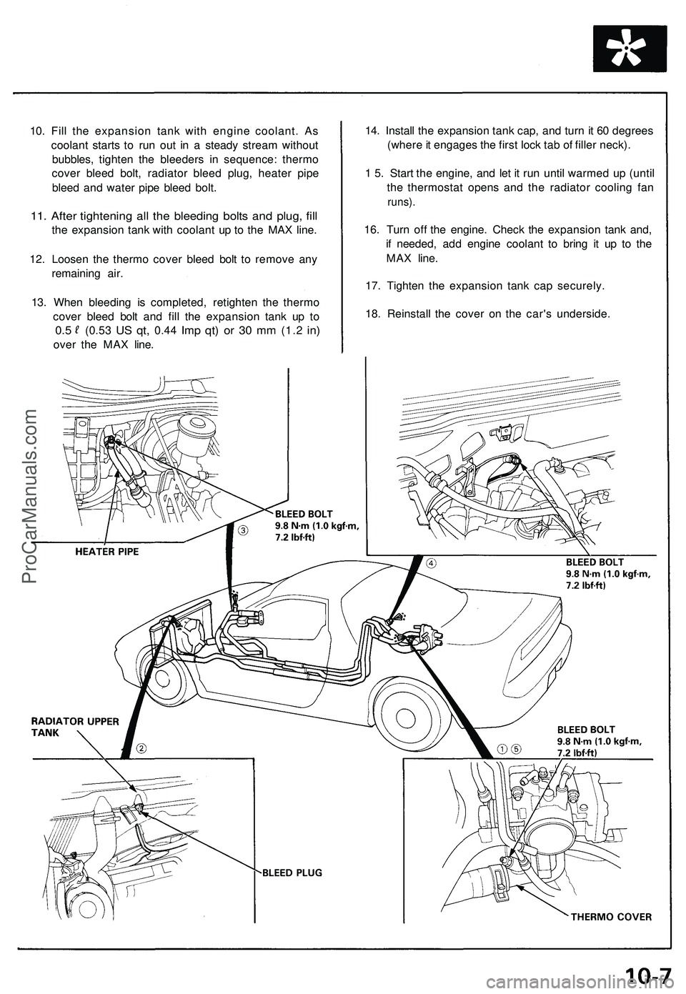
10. Fill the expansion tank with engine coolant. As
coolant starts to run out in a steady stream without
bubbles, tighten the bleeders in sequence: thermo
cover bleed bolt, radiator bleed plug, heater pipe
bleed and water pipe bleed bolt.
11. After tightening all the bleeding bolts and plug, fill
the expansion tank with coolant up to the MAX line.
12. Loosen the thermo cover bleed bolt to remove any
remaining air.
13. When bleeding is completed, retighten the thermo
cover bleed bolt and fill the expansion tank up to
0.5
(0.53
US qt,
0.44
Imp qt) or 30 mm
(1.2
in)
over the MAX line.
14. Install the expansion tank cap, and turn it 60 degrees
(where it engages the first lock tab of filler neck).
1 5. Start the engine, and let it run until warmed up (until
the thermostat opens and the radiator cooling fan
runs).
16. Turn off the engine. Check the expansion tank and,
if needed, add engine coolant to bring it up to the
MAX line.
17. Tighten the expansion tank cap securely.
18. Reinstall the cover on the car's underside.ProCarManuals.com
Page 586 of 1503
PGM-FI System
System Description (cont'd)
3. Fuel Cut-off Control
During deceleration with the throttle valve closed, current to the fuel injectors is cut off to improve fuel economy at
speeds over 1,500 rpm.
Fuel cut-off action also takes place when engine speed exceeds 8,300 rpm, regardless of the position of the throttle
valve, to protect the engine from over-revving.
4. A/C Compressor Clutch Relay
When the ECM receives a demand for cooling from the air conditioning system, it delays the compressor from being
energized, and enriches the mixture to assure smooth translation to the A/C mode.
5. Evaporative Emission (EVAP) Purge Control Solenoid Valve
When the engine coolant temperature is below 153°F (67°C), the ECM controls the EVAP purge control solenoid valve
which cuts vacuum to the EVAP purge control canister diaphragm.
6. Intake Air Bypass (IAB) Control Solenoid Valve
When the engine speed is below 4,800 rpm, the IAB control solenoid valve is activated by a signal from the ECM. Intake
air then flows through the smaller chamber, and high torque is delivered. To increase air flow at engine speeds higher
than 4,800 rpm, the solenoid valve is deactivated by the ECM, and the intake air flows through the larger chamber.
7. Exhaust Gas Recirculation (EGR) Control Solenoid Valve
When the EGR is required for control of oxides of nitrogen (NOx) emissions, the ECM supplies ground to the EGR
control solenoid valve which supplies regulated vacuum to the EGR valve.
ECM Fail-safe/Back-up Functions
1. Fail-Safe Function
When an abnormality occurs in a signal from a sensor, the ECM ignores that signal and assumes a pre-programmed
valve for that sensor that allows the engine to continue to run.
2. Back-up Function
When an abnormality occurs in the ECM itself, the fuel injectors are controlled by a back-up circuit independent of the
system in order to permit minimal driving.
3. Self-diagnosis Function [Malfunction Indicator Lamp (MIL)]
When an abnormality occurs in a signal from a sensor, the ECM lights the MIL and stores the diagnostic trouble code
in erasable memory. When the ignition is initially turned on, the ECM supplies ground for the MIL for two seconds to
check the MIL bulb condition.
4. Two Trip Detection Method
To prevent false indications, the Two Trip Detection Method is used for the H02S, fuel metering-related, idle control
system, ECT sensor, EGR system self-diagnostic functions and EVAP control system. When an abnormality occurs,
the ECM stores it in its memory. When the same abnormality recurs after the ignition switch is turned OFF and ON (II)
again, the ECM informs the driver by lighting the MIL.
However, to ease troubleshooting, this function is cancelled when you short the service check connector. The MIL will
then blink immediately when an abnormality occurs.
5. Two (or three) Driving Cycle Detection Method
A "Driving Cycle" consists of starting the engine, beginning closed loop operation, and stopping the engine. If misfir-
ing that increases emissions or EVAP control system malfunction is detected during two consecutive driving cycles,
or TWC deterioration is detected during three consecutive driving cycles, the ECM turns the MIL on.
However,
to
ease
troubleshooting,
this
function
is
cancelled when
you
short
the
service check connector.
The MIL
will
then blink immediately when an abnormality occurs.ProCarManuals.com
Page 690 of 1503
Disassembly
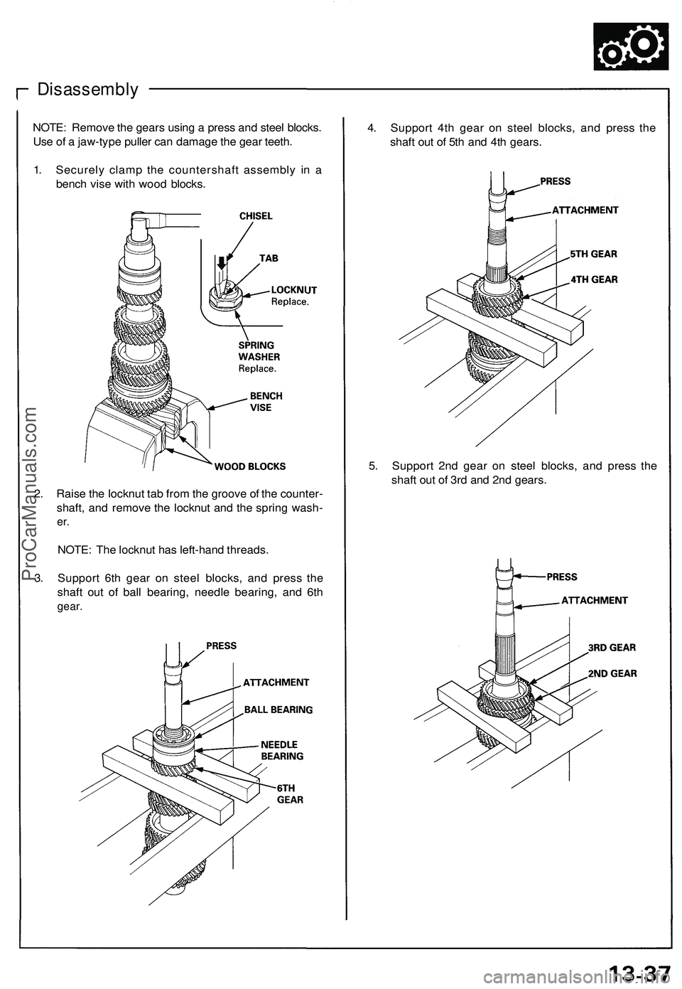
NOTE: Remove the gears using a press and steel blocks.
Use of a jaw-type puller can damage the gear teeth.
1. Securely clamp the countershaft assembly in a
bench vise with wood blocks.
4. Support 4th gear on steel blocks, and press the
shaft out of 5th and 4th gears.
5. Support 2nd gear on steel blocks, and press the
shaft out of 3rd and 2nd gears.
2. Raise the locknut tab from the groove of the counter-
shaft, and remove the locknut and the spring wash-
er.
NOTE: The locknut has left-hand threads.
3. Support 6th gear on steel blocks, and press the
shaft out of ball bearing, needle bearing, and 6th
gear.ProCarManuals.com
Page 693 of 1503
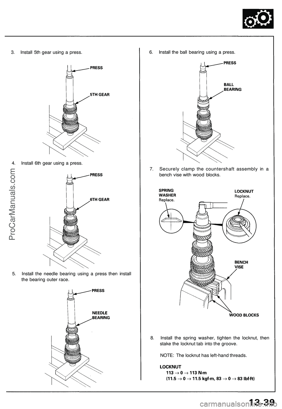
5. Install the needle bearing using a press then install
the bearing outer race.
8. Install the spring washer, tighten the locknut, then
stake the locknut tab into the groove.
NOTE: The locknut has left-hand threads.
6. Install the ball bearing using a press.
7. Securely clamp the countershaft assembly in a
bench vise with wood blocks.
3. Install 5th gear using a press.
4. Install 6th gear using a press.ProCarManuals.com
Page 705 of 1503
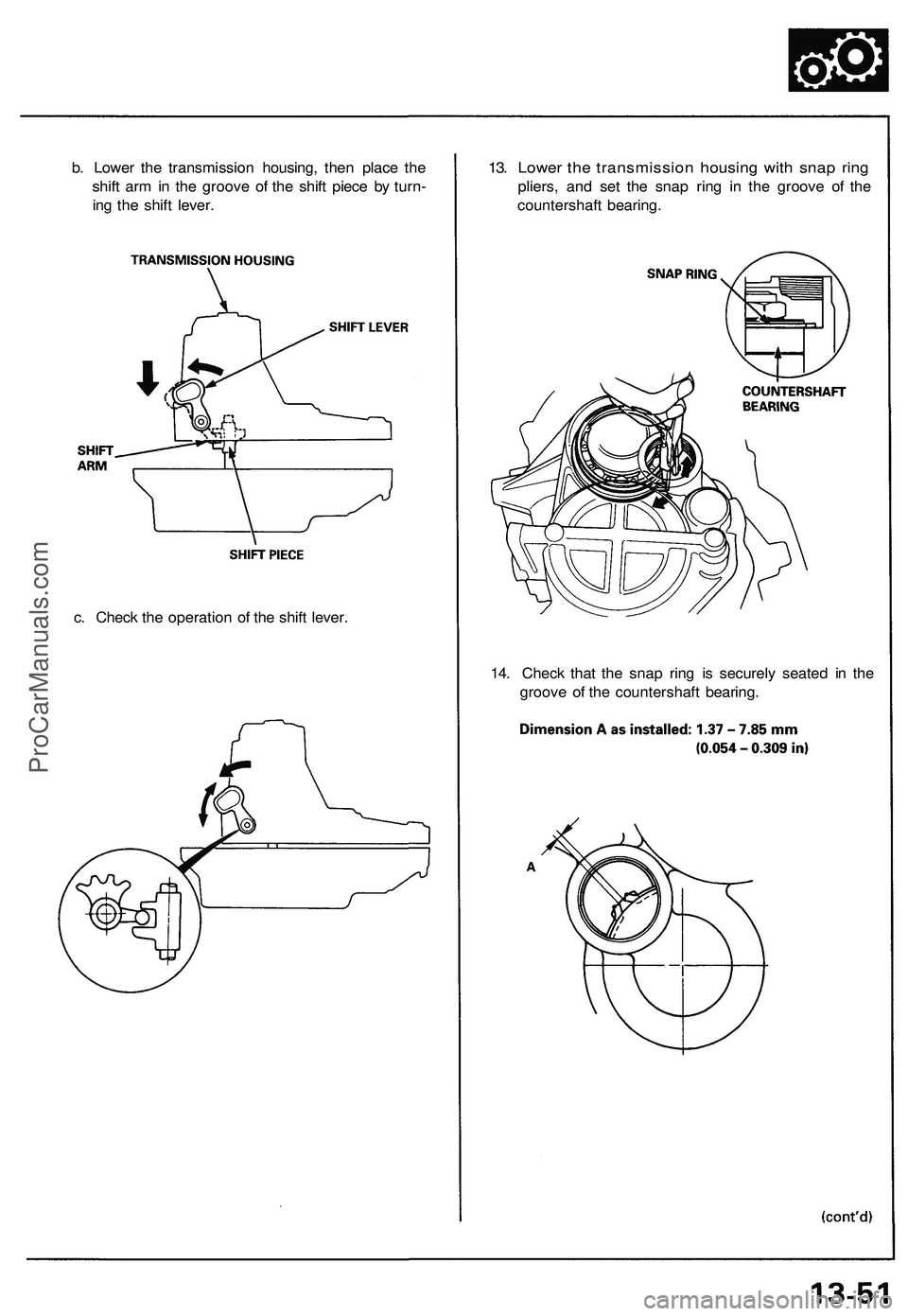
13. Lower the transmission housing with snap ring
pliers, and set the snap ring in the groove of the
countershaft bearing.
b. Lower the transmission housing, then place the
shift arm in the groove of the shift piece by turn-
ing the shift lever.
c. Check the operation of the shift lever.
14. Check that the snap ring is securely seated in the
groove of the countershaft bearing.ProCarManuals.com
Page 774 of 1503
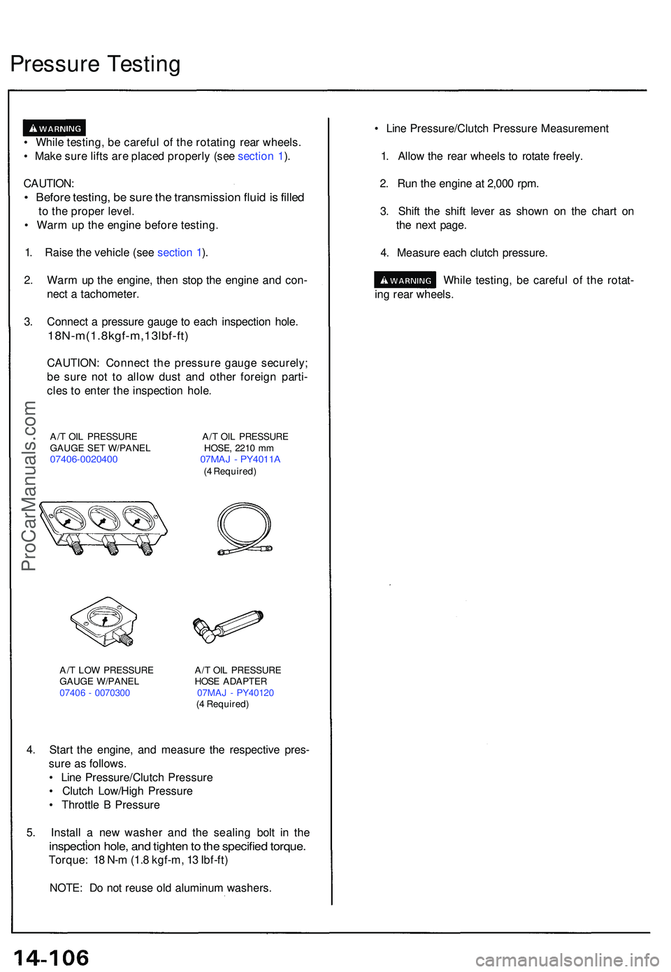
• Whil e testing , b e carefu l o f th e rotatin g rea r wheels .
• Mak e sur e lift s ar e place d properl y (se e sectio n 1 ).
CAUTION :
• Befor e testing , b e sur e th e transmissio n flui d is fille d
to th e prope r level .
• War m u p th e engin e befor e testing .
1 . Rais e th e vehicl e (se e sectio n 1 ).
2 . War m u p th e engine , the n sto p th e engin e an d con -
nec t a tachometer .
3 . Connec t a pressur e gaug e t o eac h inspectio n hole .
18N-m(1.8kgf-m,13lbf-ft )
CAUTION: Connec t th e pressur e gaug e securely ;
b e sur e no t t o allo w dus t an d othe r foreig n parti -
cle s t o ente r th e inspectio n hole .
A/T OI L PRESSUR E A/ T OI L PRESSUR E
GAUG E SE T W/PANE L HOSE , 221 0 m m
07406-002040 0 07MA J - PY4011 A(4 Required )
A/ T LO W PRESSUR E A/ T OI L PRESSUR E
GAUG E W/PANE L HOS E ADAPTE R
0740 6 - 007030 0 07MA J - PY4012 0
( 4 Required )
4. Star t th e engine , an d measur e th e respectiv e pres -
sur e a s follows .
• Lin e Pressure/Clutc h Pressur e
• Clutc h Low/Hig h Pressur e
• Throttl e B Pressur e
5 . Instal l a ne w washe r an d th e sealin g bol t i n th e
inspectio n hole , an d tighte n to th e specifie d torque .
Torque : 1 8 N- m (1. 8 kgf-m , 1 3 Ibf-ft )
NOTE : D o no t reus e ol d aluminu m washers . •
Lin e Pressure/Clutc h Pressur e Measuremen t
1 . Allo w th e rea r wheel s t o rotat e freely .
2 . Ru n th e engin e a t 2,00 0 rpm .
3 . Shif t th e shif t leve r a s show n o n th e char t o n
th e nex t page .
4 . Measur e eac h clutc h pressure .
While testing , b e carefu l o f th e rotat -
in g rea r wheels .
Pressur e Testin g
ProCarManuals.com
Page 819 of 1503
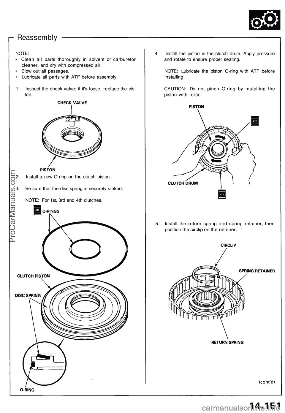
Reassembly
NOTE:
• Clean all parts thoroughly in solvent or carburetor
cleaner, and dry with compressed air.
• Blow out all passages.
• Lubricate all parts with ATF before assembly.
1. Inspect the check valve; if it's loose, replace the pis-
ton.
4. Install the piston in the clutch drum. Apply pressure
and rotate to ensure proper seating.
NOTE: Lubricate the piston O-ring with ATF before
installing.
CAUTION: Do not pinch O-ring by installing the
piston with force.
2. Install a new O-ring on the clutch piston.
3. Be sure that the disc spring is securely staked.
NOTE: For 1st, 3rd and 4th clutches.
5. Install the return spring and spring retainer, then
position the circlip on the retainer.ProCarManuals.com
Page 876 of 1503
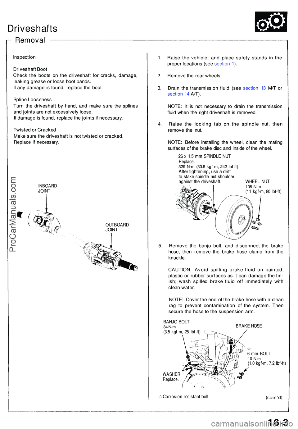
Driveshafts
Inspection
Driveshaf t Boo t
Chec k th e boot s o n th e driveshaf t fo r cracks , damage ,
leakin g greas e o r loos e boo t bands .
I f an y damag e i s found , replac e th e boo t
Splin e Loosenes s
Turn th e driveshaf t b y hand , an d mak e sur e th e spline s
an d joint s ar e no t excessivel y loose .
I f damag e is found , replac e th e joint s i f necessary .
Twiste d o r Cracked
Mak e sur e th e driveshaf t i s not twiste d o r cracked .
Replace i f necessary .
INBOARDJOINT
OUTBOAR DJOINT
1. Rais e th e vehicle , an d plac e safet y stand s i n th e
prope r location s (se e sectio n 1 ).
2 . Remov e th e rea r wheels .
3 . Drai n th e transmissio n flui d (se e sectio n 1 3 M/ T o r
sectio n 1 4 A/T) .
NOTE : I t i s no t necessar y t o drai n th e transmissio n
flui d whe n th e righ t driveshaf t i s removed .
4 . Rais e th e lockin g ta b o n th e spindl e nut , the n
remov e th e nut .
NOTE : Befor e installin g th e wheel , clea n th e matin g
surface s o f th e brak e dis c an d insid e o f th e wheel .
26 x 1. 5 m m SPINDL E NU TReplace .329 N- m (33. 5 kgf m , 24 2 Ib f ft )Afte r tightening , us e a drif tto stak e spindl e nu t shoulde ragainst th e driveshaft . WHEE L NU T108 N- m(11 kgf-m , 8 0 Ibf-ft )
5. Remov e th e banj o bolt , an d disconnec t th e brak e
hose , the n remov e th e brak e hos e clam p fro m th e
knuckle .
CAUTION : Avoi d spillin g brak e flui d o n painted ,
plasti c o r rubbe r surface s a s i t ca n damag e th e fin -
ish ; was h spille d brak e flui d of f immediatel y wit h
clea n water .
NOTE : Cove r th e en d o f th e brak e hos e wit h a clea n
ra g t o preven t contaminatio n o f th e system . The n
secur e th e hos e t o th e suspensio n arm .
BANJ O BOL T34 N-m(3.5 kg f m , 2 5 Ibf-ft )
WASHE RReplace .
Corrosio n resistan t bol t
BRAK E HOS E
6 m m BOL T10 N- m(1.0 kgf-m , 7. 2 Ibf-ft )
Remova l
ProCarManuals.com
Page 877 of 1503
Driveshafts
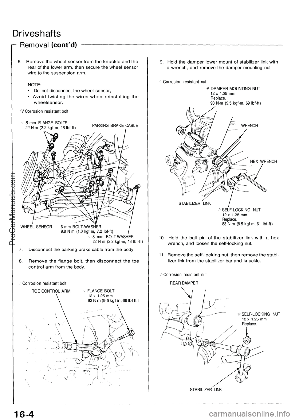
Removal
6. Remove the wheel sensor from the knuckle and the
rear of the lower arm, then secure the wheel sensor
wire to the suspension arm.
NOTE:
• Do not disconnect the wheel sensor,
• Avoid twisting the wires when reinstalling the
wheel sensor.
V Corrosion resistant bolt
8 mm FLANGE BOLTS
22 N-m (2.2 kgf-m, 16 Ibf-ft)
PARKING BRAKE CABLE
WHEEL SENSOR 6 mm BOLT-WASHER
9.8 N m (1.0 kgf m, 7.2 Ibf-ft)
8 mm BOLT-WASHER
22 N m (2.2 kgf-m, 16 Ibf-ft)
7. Disconnect the parking brake cable from the body.
8. Remove the flange bolt, then disconnect the toe
control arm from the body.
Corrosion resistant bolt
TOE CONTROL ARM
FLANGE BOLT
12 x
1.25
mm
93 N m
(9.5
kgf in, 69 Ibf ft I
9. Hold the damper lower mount of stabilizer link with
a wrench, and remove the damper mounting nut.
Corrosion resistant nut
A DAMPER MOUNTING NUT
12 x
1.25
mm
Replace.
93 N-m (9.5 kgf-m, 69 Ibf-ft)
WRENCH
HEX WRENCH
STABILIZER LINK
SELF-LOCKING NUT
12 x
1.25
mm
Replace.
83 N m (8.5 kgf m, 61 Ibf-ft)
10. Hold the ball pin of the stabilizer link with a hex
wrench, and loosen the self-locking nut.
11. Remove the self-locking nut, then remove the stabi-
lizer link from the stabilizer bar and knuckle.
Corrosion resistant nut
REAR DAMPER
SELF-LOCKING NUT
12 x
1.25
mm
Replace.
STABILIZER LINKProCarManuals.com
Page 893 of 1503
System Description
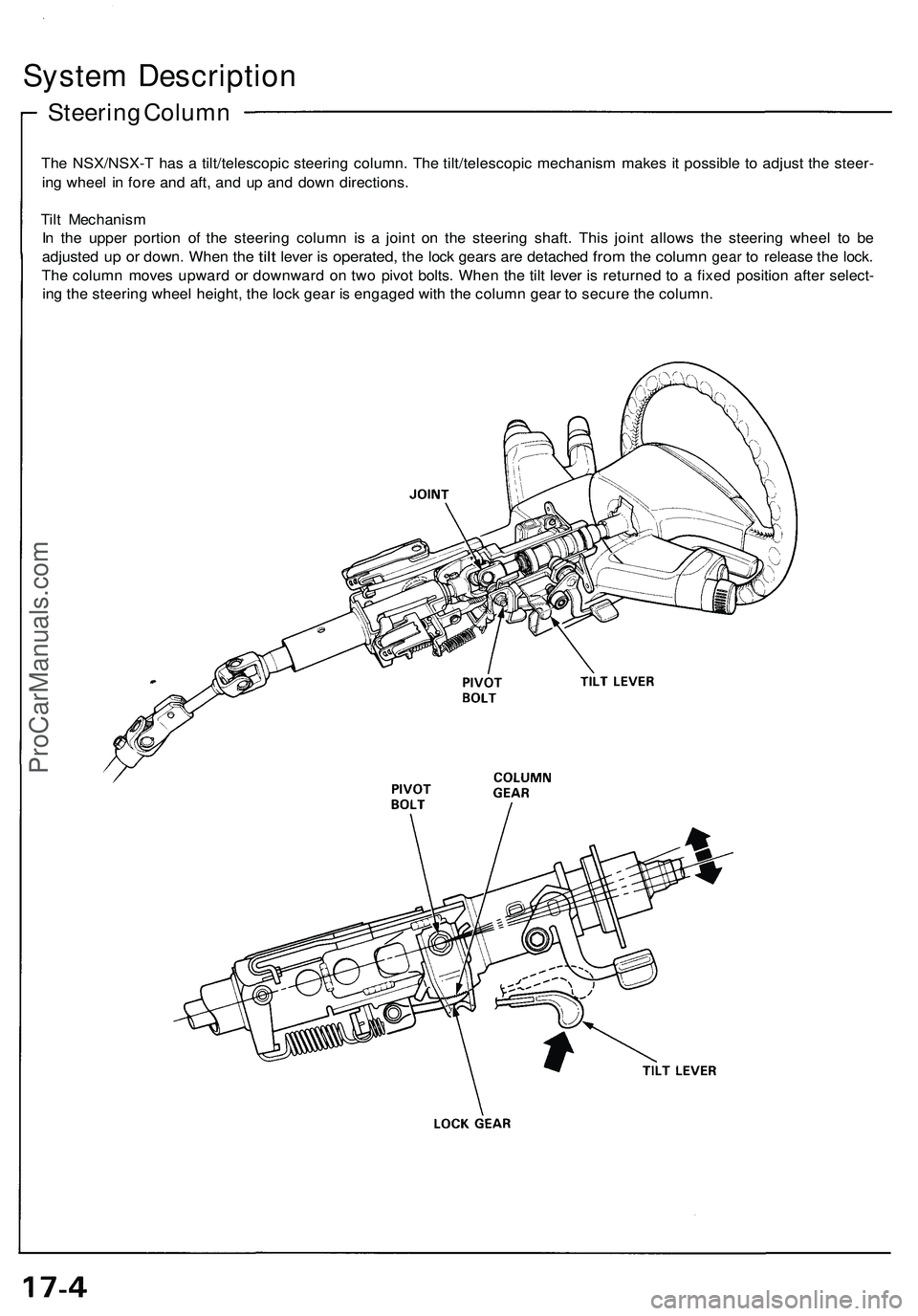
Steering Column
The NSX/NSX-T has a tilt/telescopic steering column. The tilt/telescopic mechanism makes it possible to adjust the steer-
ing wheel in fore and aft, and up and down directions.
Tilt Mechanism
In the upper portion of the steering column is a joint on the steering shaft. This joint allows the steering wheel to be
adjusted
up or
down. When
the
tilt
lever
is
operated,
the
lock gears
are
detached
from
the
column
gear
to
release
the
lock.
The column moves upward or downward on two pivot bolts. When the tilt lever is returned to a fixed position after select-
ing the steering wheel height, the lock gear is engaged with the column gear to secure the column.ProCarManuals.com