ECU ACURA NSX 1997 Service Owner's Guide
[x] Cancel search | Manufacturer: ACURA, Model Year: 1997, Model line: NSX, Model: ACURA NSX 1997Pages: 1503, PDF Size: 57.08 MB
Page 917 of 1503
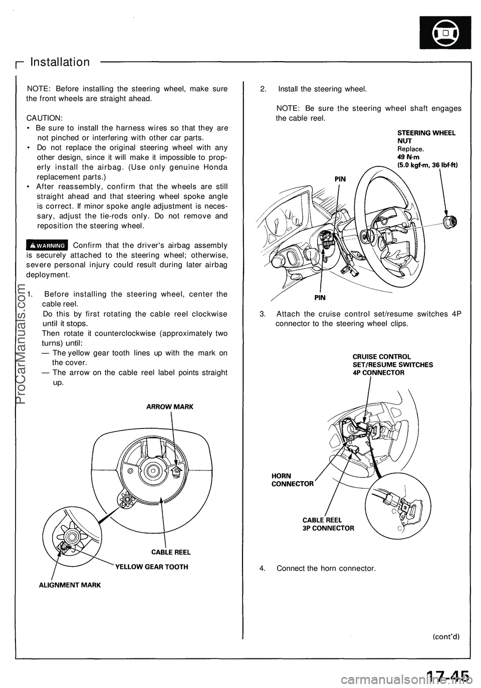
4. Connect the horn connector.
Installation
NOTE: Before installing the steering wheel, make sure
the front wheels are straight ahead.
CAUTION:
• Be sure to install the harness wires so that they are
not pinched or interfering with other car parts.
• Do not replace the original steering wheel with any
other design, since it will make it impossible to prop-
erly install the airbag. (Use only genuine Honda
replacement parts.)
• After reassembly, confirm that the wheels are still
straight ahead and that steering wheel spoke angle
is correct. If minor spoke angle adjustment is neces-
sary, adjust the tie-rods only. Do not remove and
reposition the steering wheel.
Confirm that the driver's airbag assembly
is securely attached to the steering wheel; otherwise,
severe personal injury could result during later airbag
deployment.
1. Before installing the steering wheel, center the
cable reel.
Do this by first rotating the cable reel clockwise
until it stops.
Then rotate it counterclockwise (approximately two
turns) until:
— The yellow gear tooth lines up with the mark on
the cover.
— The arrow on the cable reel label points straight
up.
2. Install the steering wheel.
NOTE: Be sure the steering wheel shaft engages
the cable reel.
3. Attach the cruise control set/resume switches 4P
connector to the steering wheel clips.ProCarManuals.com
Page 922 of 1503
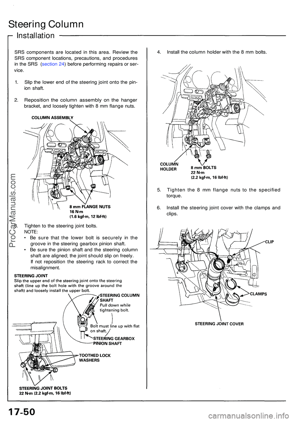
Steering Colum n
Installatio n
SRS component s ar e locate d i n thi s area . Revie w th e
SR S componen t locations , precautions , an d procedure s
i n th e SR S ( sectio n 24 ) befor e performin g repair s o r ser -
vice .
1. Sli p th e lowe r en d o f th e steerin g join t ont o th e pin -
io n shaft .
2. Repositio n th e colum n assembl y o n th e hange r
bracket , an d loosel y tighte n wit h 8 m m flang e nuts . 4
. Instal l th e colum n holde r wit h th e 8 m m bolts .
3 . Tighte n t o th e steerin g join t bolts .
NOTE :
• B e sur e tha t th e lowe r bol t i s securel y i n th e
groov e in th e steerin g gearbo x pinio n shaft .
• B e sur e th e pinio n shaf t an d th e steerin g colum n
shaf t ar e aligned ; th e join t shoul d sli p o n freely .
I f no t repositio n th e steerin g rac k t o correc t th e
misalignment . 5
. Tighte n th e 8 m m flang e nut s t o th e specifie d
torque .
6 . Instal l th e steerin g join t cove r wit h th e clamp s an d
clips .
ProCarManuals.com
Page 928 of 1503
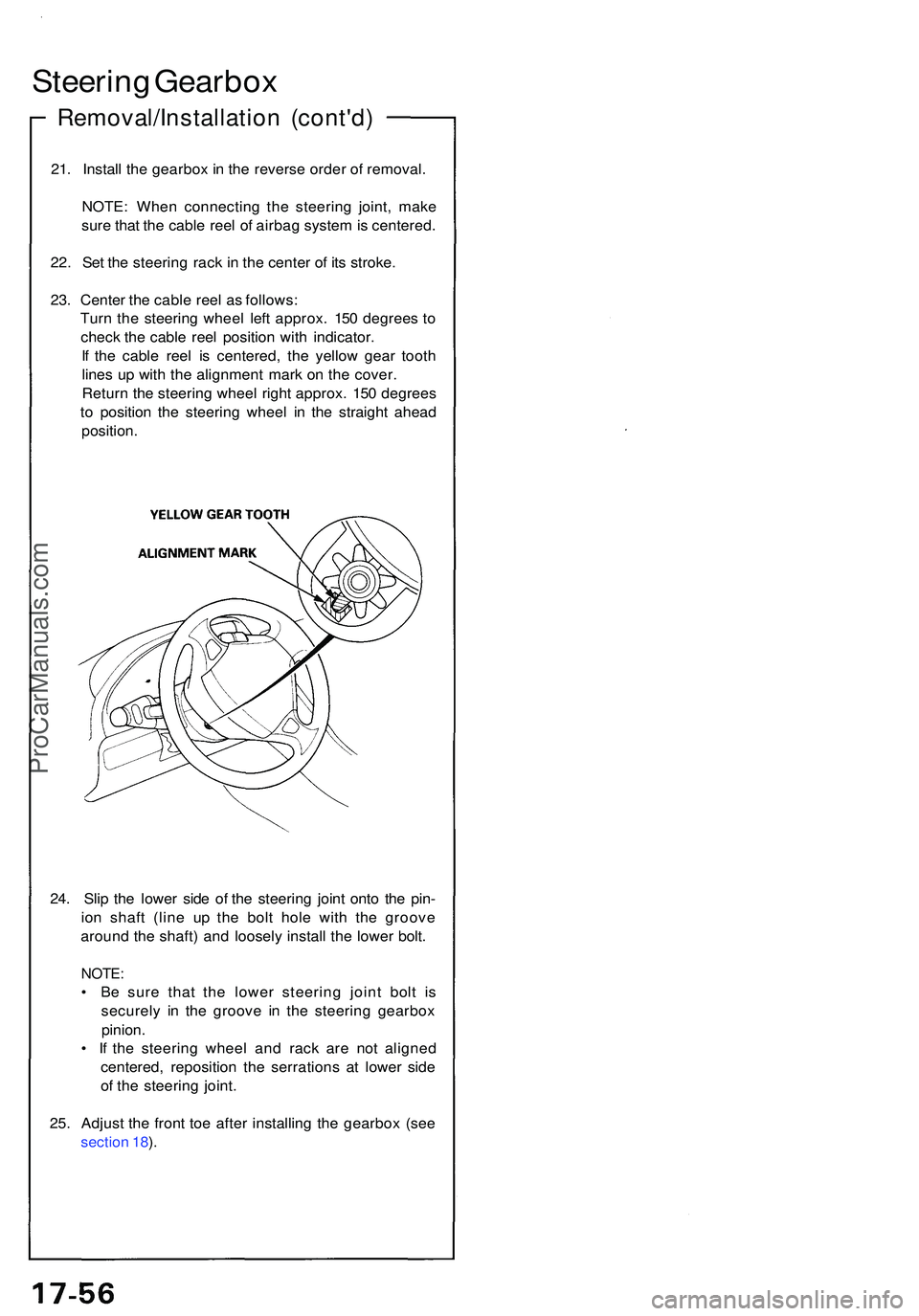
24. Sli p th e lowe r sid e o f th e steerin g join t ont o th e pin -
io n shaf t (lin e u p th e bol t hol e wit h th e groov e
aroun d th e shaft ) an d loosel y instal l th e lowe r bolt .
NOTE :
• B e sur e tha t th e lowe r steerin g join t bol t i s
securel y i n th e groov e i n th e steerin g gearbo x
pinion .
• I f th e steerin g whee l an d rac k ar e no t aligne d
centered , repositio n th e serration s a t lowe r sid e
o f th e steerin g joint .
25 . Adjus t th e fron t to e afte r installin g th e gearbo x (se e
sectio n 18 ).
21
. Instal l th e gearbo x in th e revers e orde r o f removal .
NOTE : Whe n connectin g th e steerin g joint , mak e
sur e tha t th e cabl e ree l o f airba g syste m is centered .
22 . Se t th e steerin g rac k i n th e cente r o f it s stroke .
23 . Cente r th e cabl e ree l a s follows :
Tur n th e steerin g whee l lef t approx . 15 0 degree s t o
chec k th e cabl e ree l positio n wit h indicator .
I f th e cabl e ree l i s centered , th e yello w gea r toot h
line s u p wit h th e alignmen t mar k o n th e cover .
Retur n th e steerin g whee l righ t approx . 15 0 degree s
t o positio n th e steerin g whee l i n th e straigh t ahea d
position .
Steering Gearbo x
Removal/Installatio n (cont'd )
ProCarManuals.com
Page 931 of 1503
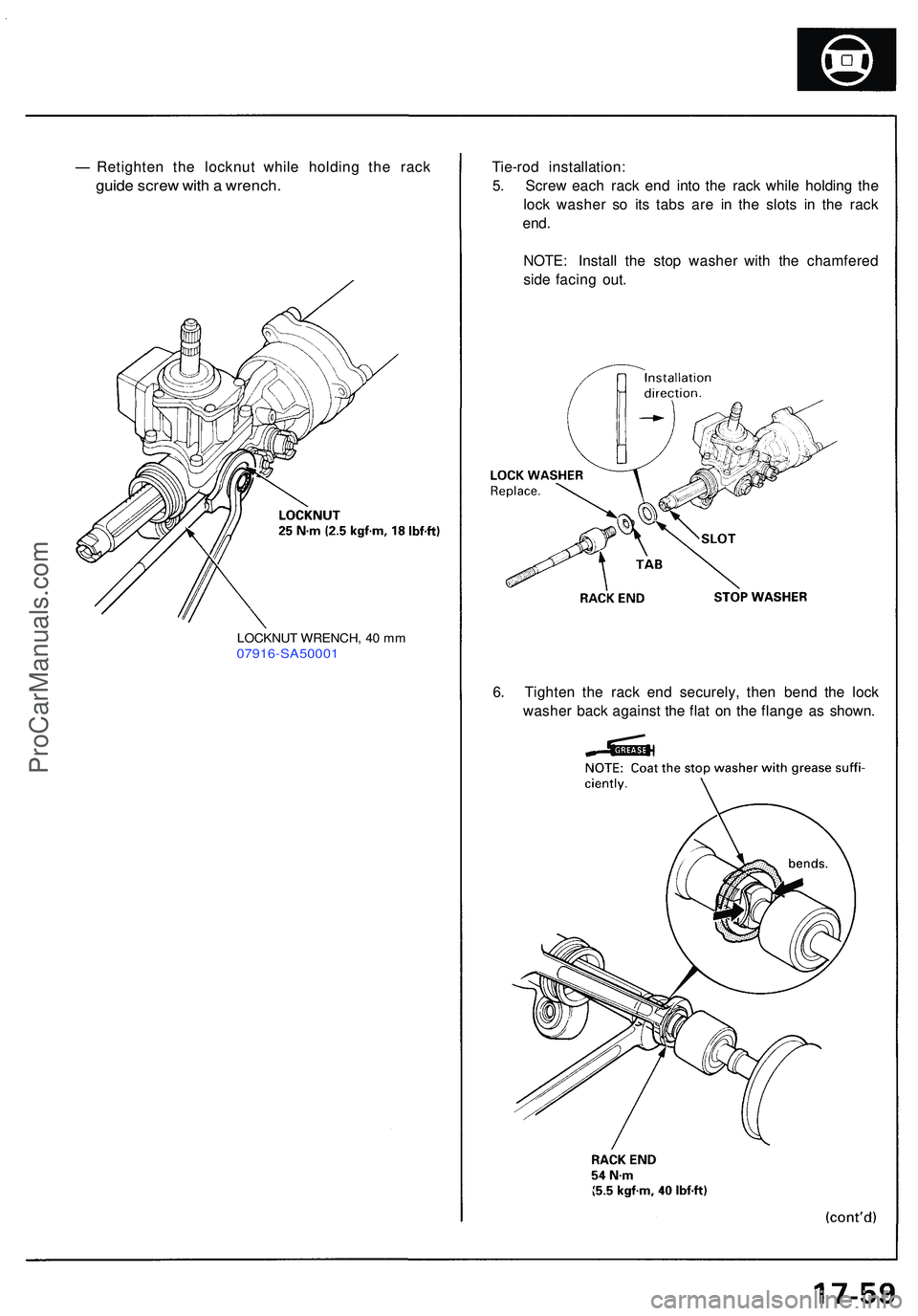
Tie-rod installation :
5 . Scre w eac h rac k en d int o th e rac k whil e holdin g th e
loc k washe r s o it s tab s ar e i n th e slot s i n th e rac k
end.
NOTE : Instal l th e sto p washe r wit h th e chamfere d
sid e facin g out .
6 . Tighte n th e rac k en d securely , the n ben d th e loc k
washe r bac k agains t th e fla t o n th e flang e a s shown .
Retighte
n th e locknu t whil e holdin g th e rac k
guide scre w wit h a wrench .
LOCKNU T WRENCH , 4 0 m m07916-SA5000 1
ProCarManuals.com
Page 933 of 1503
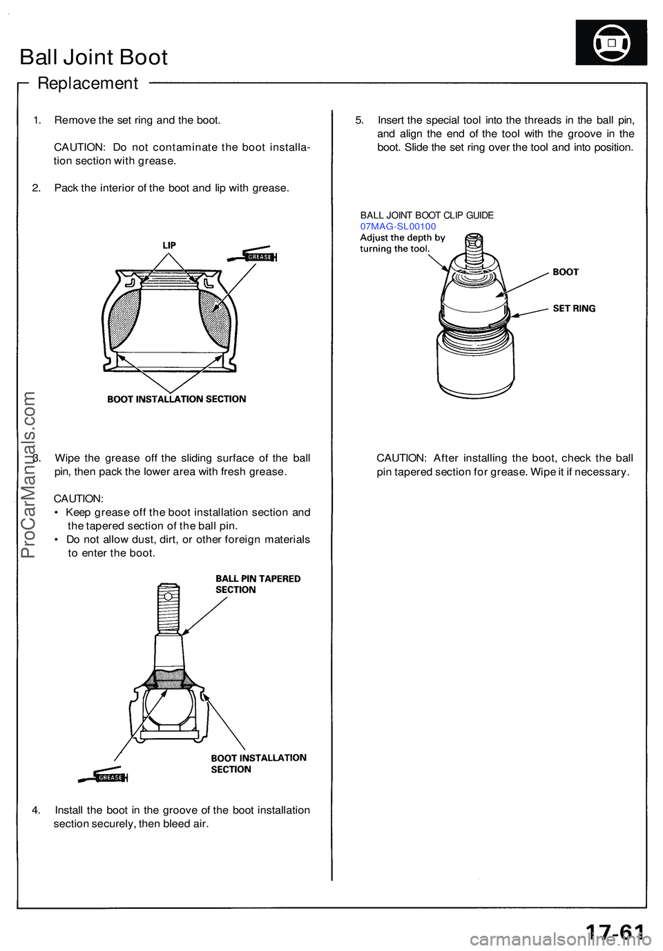
4. Instal l th e boo t i n th e groov e o f th e boo t installatio n
sectio n securely , the n blee d air .
3
. Wip e th e greas e of f th e slidin g surfac e o f th e bal l
pin , the n pac k th e lowe r are a wit h fres h grease .
CAUTION :
• Kee p greas e of f th e boo t installatio n sectio n an d
th e tapere d sectio n o f th e bal l pin .
• D o no t allo w dust , dirt , o r othe r foreig n material s
t o ente r th e boot .
Ball Join t Boo t
Replacemen t
1. Remov e th e se t rin g an d th e boot .
CAUTION : D o no t contaminat e th e boo t installa -
tio n sectio n wit h grease .
2 . Pac k th e interio r o f th e boo t an d li p wit h grease . 5
. Inser t th e specia l too l int o th e thread s i n th e bal l pin ,
an d alig n th e en d o f th e too l wit h th e groov e i n th e
boot . Slid e th e se t rin g ove r th e too l an d int o position .
BALL JOIN T BOO T CLI P GUID E07MAG-SL0010 0
CAUTION: Afte r installin g th e boot , chec k th e bal l
pi n tapere d sectio n fo r grease . Wip e it i f necessary .
ProCarManuals.com
Page 959 of 1503
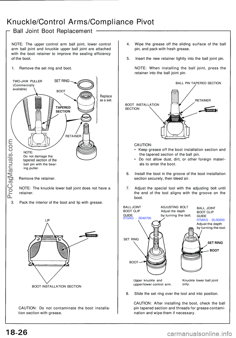
Knuckle/Control Arms/Complianc e Pivo t
Ball Join t Boo t Replacemen t
NOTE: Th e uppe r contro l ar m bal l joint , lowe r contro l
ar m bal l join t an d knuckl e uppe r bal l join t ar e attache d
wit h th e boo t retaine r t o improv e th e sealin g efficienc y
of th e boot .
1. Remov e th e se t rin g an d boot .
TWO-JA W PULLE R
(Commerciall y
available )
Replaceas a set .
NOTE :Do no t damag e th etapere d sectio n o f th ebal l pi n wit h th e bear -ing puller .
2. Remov e th e retainer .
NOTE : Th e knuckl e lowe r bal l join t doe s no t hav e a
retainer .
3. Pac k th e interio r o f th e boo t an d li p wit h grease .
BOOT INSTALLATIO N SECTIO N
CAUTION : D o no t contaminat e th e boo t installa -
tio n sectio n wit h grease . 4
. Wip e th e greas e of f th e slidin g surfac e o f th e bal l
pin , an d pac k wit h fres h grease .
5 . Inser t th e ne w retaine r lightl y int o th e bal l join t pin .
NOTE : Whe n installin g th e bal l joint , pres s th e
retaine r int o th e bal l join t pin .
BAL L PI N TAPERE D SECTIO N
BOO T INSTALLATIO N
SECTION
CAUTION :
• Kee p greas e of f th e boo t installatio n sectio n an d
th e tapere d sectio n o f th e bal l pin .
• D o no t allo w dust , dirt , o r othe r foreig n materi -
al s t o ente r th e boot .
6 . Instal l th e boo t i n th e groov e o f th e boo t installatio n
sectio n securely , the n blee d air .
7 . Adjus t th e specia l too l wit h th e adjustin g bol t unti l
th e en d o f th e too l align s wit h th e groov e o n th e
boot .
BAL L JOIN T ADJUSTIN G BOL T
BOO T CLI P Adjus t th e dept h
GUIDE by turnin g the bolt .07GA G - SD4070 0
SE T RIN G
BOO T
Uppe r knuckl e an d
upper/lowe r contro l arm .
BALL JOIN T
BOO T CLI P
GUID E
07MA G - SL0020 0Adjust th e dept hby turnin g th e tool .
Knuckl e lowe r bal l join tonly.
8. Slid e th e se t rin g ove r th e too l an d int o position .
CAUTION : Afte r installin g th e boot , chec k th e bal l
pi n tapere d sectio n an d thread s fo r greas e contami -
natio n an d wip e the m if necessary .
SET RIN G
BOO T
RETAINE R
RETAINER
LIP
ProCarManuals.com
Page 961 of 1503
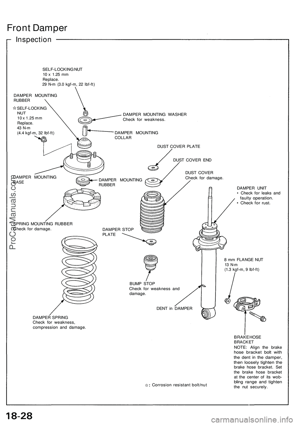
Front Dampe r
Inspectio n
SELF-LOCKIN G NU T10 x 1.2 5 mmReplace .29 N- m (3. 0 kgf-m , 2 2 Ibf-ft )
DAMPE R MOUNTIN GRUBBER
SELF-LOCKIN GNUT10 x 1.25 mmReplace .43 N- m(4.4 kgf-m , 3 2 Ibf-ft )
DAMPE R MOUNTIN GBASE
DAMPE R MOUNTIN G WASHE R
Chec k fo r weakness .
DAMPE R MOUNTIN G
COLLAR
DAMPE R MOUNTIN GRUBBER
DUST COVE R PLAT E
DUS T COVE R EN D
DUS T COVE R
Chec k fo r damage .
SPRIN G MOUNTIN G RUBBE R
Chec k fo r damage .
DAMPER STO P
PLAT E
DAMPE R SPRIN G
Chec k fo r weakness ,
compressio n an d damage . DAMPE
R UNI T
• Chec k fo r leak s an d
fault y operation .• Chec k fo r rust .
8 m m FLANG E NU T13 N- m(1.3 kgf-m , 9 Ibf-ft )
BUMP STO P
Chec k fo r weaknes s an d
damage .
DENT i n DAMPE R
Corrosio n resistan t bolt/nu t BRAK
E HOS E
BRACKETNOTE : Alig n th e brak ehose bracke t bol t wit hthe den t i n th e damper ,then loosel y tighte n th ebrak e hos e bracket . Se t
th e brak e hos e bracke t
a t th e cente r o f it s wob -
bling rang e an d tighte nthe nu t securely .
ProCarManuals.com
Page 962 of 1503
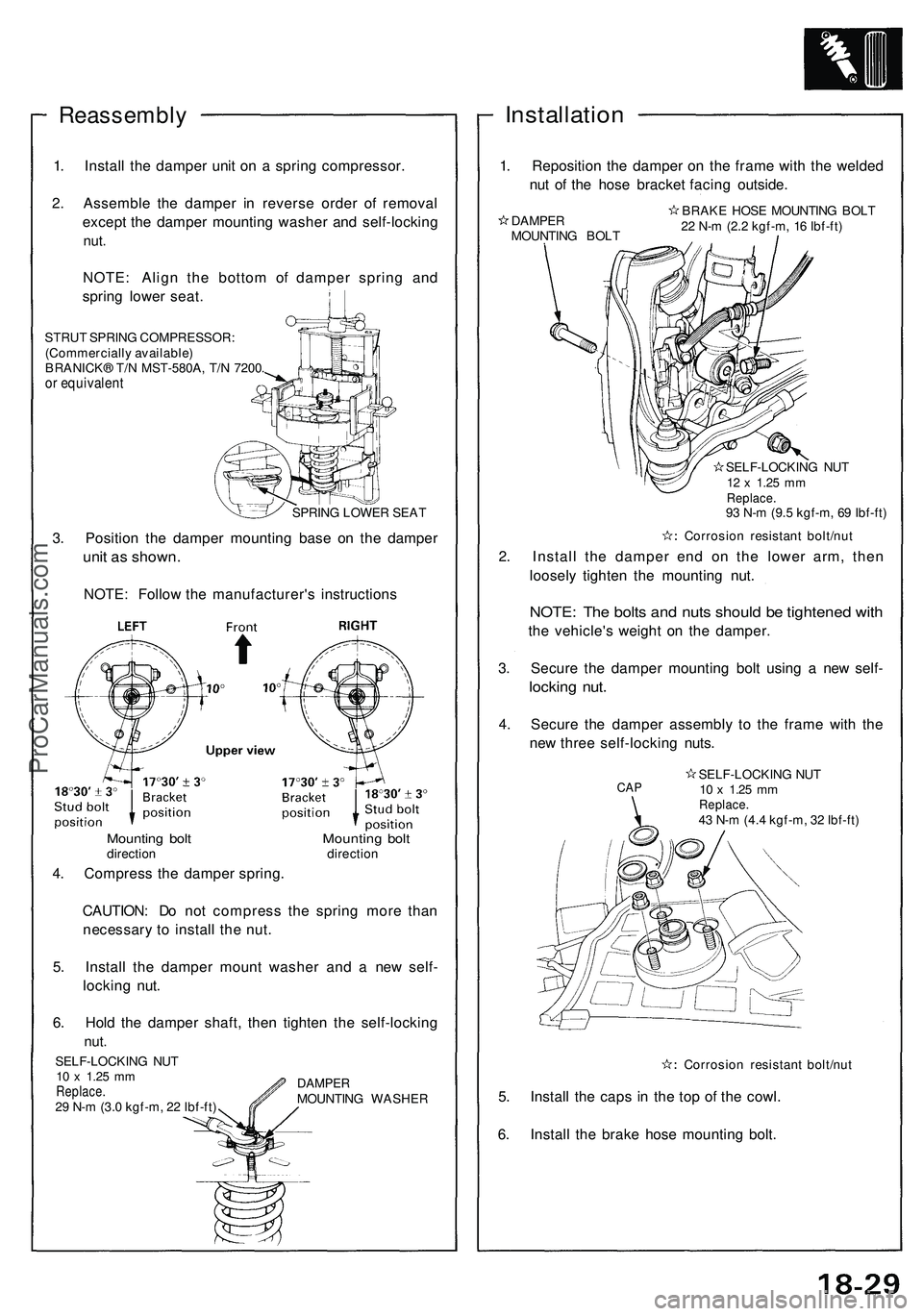
Reassembly
1. Install the damper unit on a spring compressor.
2. Assemble the damper in reverse order of removal
except the damper mounting washer and self-locking
nut.
NOTE: Align the bottom of damper spring and
spring lower seat.
STRUT SPRING COMPRESSOR:
(Commercially available)
BRANICK® T/N MST-580A, T/N 7200.
or equivalent
SPRING LOWER SEAT
3. Position the damper mounting base on the damper
unit as shown.
NOTE: Follow the manufacturer's instructions
CAUTION: Do not compress the spring more than
necessary to install the nut.
5. Install the damper mount washer and a new self-
locking nut.
6. Hold the damper shaft, then tighten the self-locking
nut.
Installation
1. Reposition the damper on the frame with the welded
nut of the hose bracket facing outside.
DAMPER
MOUNTING BOLT
BRAKE HOSE MOUNTING BOLT
22 N-m (2.2 kgf-m, 16 Ibf-ft)
SELF-LOCKING NUT
12 x
1.25
mm
Replace.
93 N-m (9.5 kgf-m, 69 Ibf-ft)
Corrosion resistant bolt/nut
2. Install the damper end on the lower arm, then
loosely tighten the mounting nut.
NOTE: The bolts and nuts should be tightened with
the vehicle's weight on the damper.
3. Secure the damper mounting bolt using a new self-
locking nut.
4. Secure the damper assembly to the frame with the
new three self-locking nuts.
Corrosion resistant bolt/nut
5. Install the caps in the top of the cowl.
6. Install the brake hose mounting bolt.
Mounting bolt Mounting bolt
direction direction
4. Compress the damper spring.
SELF-LOCKING NUT
10 x
1.25
mm
Replace.
29 N-m (3.0 kgf-m, 22 Ibf-ft)
DAMPER
MOUNTING WASHER
CAP
SELF-LOCKING NUT
10 x
1.25
mm
Replace.
43 N-m (4.4 kgf-m, 32 Ibf-ft)ProCarManuals.com
Page 965 of 1503
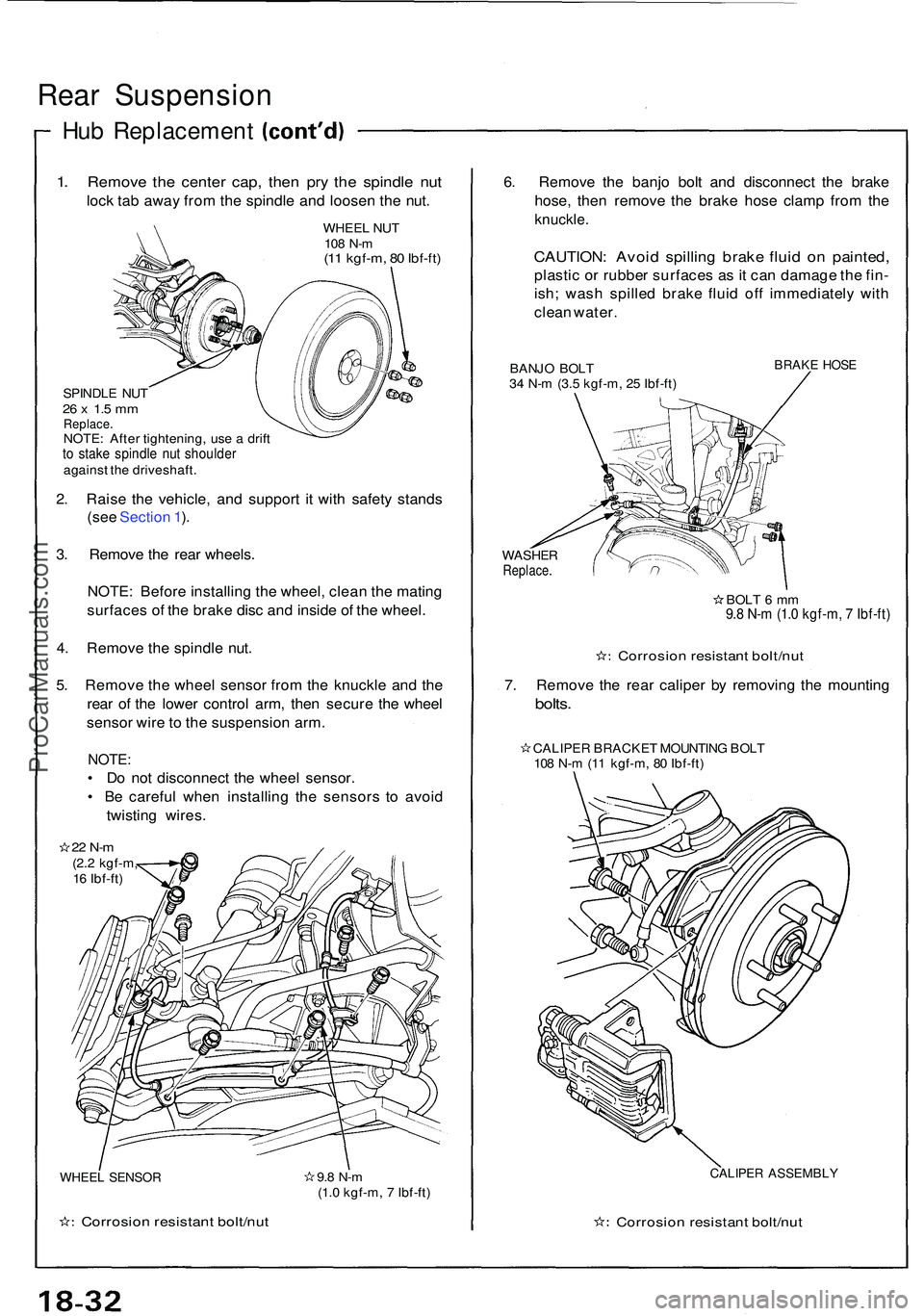
Rear Suspensio n
Hub Replacemen t
1. Remov e th e cente r cap , the n pr y th e spindl e nu t
lock ta b awa y fro m th e spindl e an d loose n th e nut .
WHEE L NU T108 N- m(11 kgf-m , 8 0 Ibf-ft )
SPINDL E NU T26 x 1. 5 m mReplace .NOTE: Afte r tightening , us e a drif tto stak e spindl e nu t shoulde ragainst th e driveshaft .
2. Rais e th e vehicle , an d suppor t i t wit h safet y stand s
(se e Sectio n 1 ).
3 . Remov e th e rea r wheels .
NOTE : Befor e installin g th e wheel , clea n th e matin g
surface s o f th e brak e dis c an d insid e o f th e wheel .
4 . Remov e th e spindl e nut .
5 . Remov e th e whee l senso r fro m th e knuckl e an d th e
rea r o f th e lowe r contro l arm , the n secur e th e whee l
senso r wir e to th e suspensio n arm .
NOTE :
• D o no t disconnec t th e whee l sensor .
• B e carefu l whe n installin g th e sensor s t o avoi d
twistin g wires .
22 N- m(2.2 kgf-m ,
1 6 Ibf-ft )
WHEE L SENSO R
Corrosio n resistan t bolt/nu t
9.8 N- m(1.0 kgf-m , 7 Ibf-ft )
6. Remov e th e banj o bol t an d disconnec t th e brak e
hose , the n remov e th e brak e hos e clam p fro m th e
knuckle .
CAUTION : Avoi d spillin g brak e flui d o n painted ,
plastic o r rubbe r surface s a s it ca n damag e th e fin -
ish ; was h spille d brak e flui d of f immediatel y wit h
clea n water .
BANJO BOL T
3 4 N- m (3. 5 kgf-m , 2 5 Ibf-ft )BRAK E HOS E
WASHE RReplace .
BOLT 6 m m9.8 N- m (1. 0 kgf-m , 7 Ibf-ft )
Corrosio n resistan t bolt/nu t
7. Remov e th e rea r calipe r b y removin g th e mountin g
bolts.
CALIPE R BRACKE T MOUNTIN G BOL T
10 8 N- m (1 1 kgf-m , 8 0 Ibf-ft )
CALIPE R ASSEMBL Y
Corrosion resistan t bolt/nu t
ProCarManuals.com
Page 972 of 1503
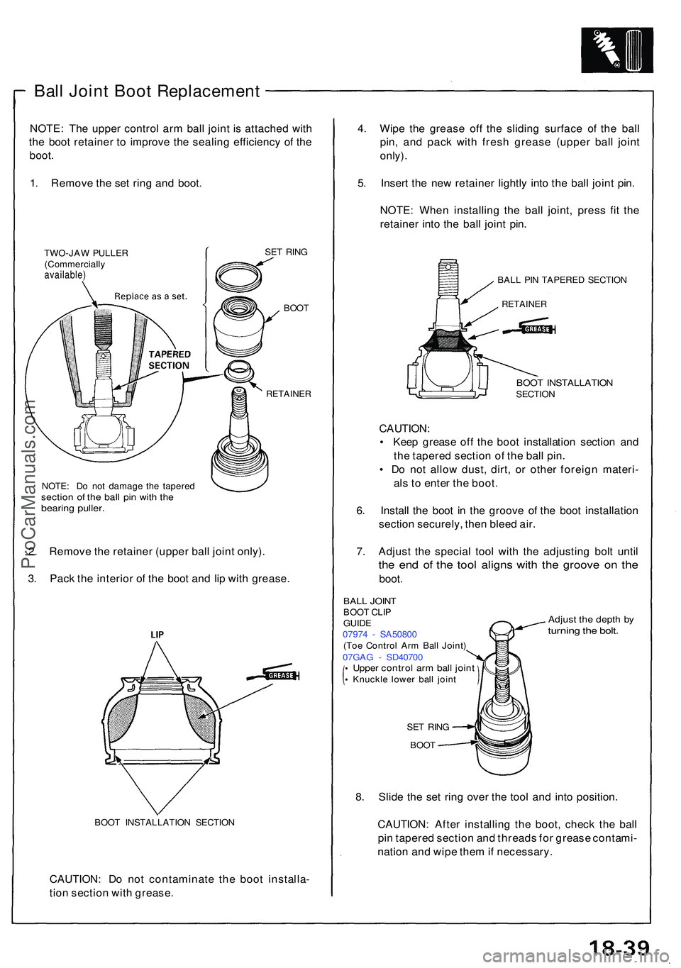
Ball Join t Boo t Replacemen t
NOTE: Th e uppe r contro l ar m bal l join t i s attache d wit h
th e boo t retaine r t o improv e th e sealin g efficienc y o f th e
boot .
1 . Remov e th e se t rin g an d boot .
TWO-JA W PULLE R
(Commerciall y
available)
SET RIN G
BOO T
RETAINE R
NOTE: D o no t damag e th e tapere dsection o f th e bal l pi n wit h th ebearin g puller .
2. Remov e th e retaine r (uppe r bal l join t only) .
3 . Pac k th e interio r o f th e boo t an d li p wit h grease .
BOOT INSTALLATIO N SECTIO N
CAUTION : D o no t contaminat e th e boo t installa -
tio n sectio n wit h grease . 4
. Wip e th e greas e of f th e slidin g surfac e o f th e bal l
pin , an d pac k wit h fres h greas e (uppe r bal l join t
only) .
5. Inser t th e ne w retaine r lightl y int o th e bal l join t pin .
NOTE : Whe n installin g th e bal l joint , pres s fi t th e
retaine r int o th e bal l join t pin .
BAL L PI N TAPERE D SECTIO N
RETAINE R
BOOT INSTALLATIO NSECTION
CAUTION :
• Kee p greas e of f th e boo t installatio n sectio n an d
th e tapere d sectio n o f th e bal l pin .
• D o no t allo w dust , dirt , o r othe r foreig n materi -
al s to ente r th e boot .
6 . Instal l th e boo t i n th e groov e o f th e boo t installatio n
sectio n securely , the n blee d air .
7 . Adjus t th e specia l too l wit h th e adjustin g bol t unti l
the en d o f th e too l align s wit h th e groov e o n th e
boot .
Adjus t th e dept h b yturnin g th e bolt .
BAL L JOIN TBOOT CLI P
GUID E
0797 4 - SA5080 0
(To e Contro l Ar m Bal l Joint )
07GA G - SD4070 0
Upper contro l ar m bal l join tKnuckl e lowe r bal l join t
SE T RIN G
BOO T
8. Slid e th e se t rin g ove r th e too l an d int o position .
CAUTION : Afte r installin g th e boot , chec k th e bal l
pi n tapere d sectio n an d thread s fo r greas e contami -
natio n an d wip e the m if necessary .
ProCarManuals.com