ACURA NSX 1997 Service Repair Manual
Manufacturer: ACURA, Model Year: 1997,
Model line: NSX,
Model: ACURA NSX 1997
Pages: 1503, PDF Size: 57.08 MB
ACURA NSX 1997 Service Repair Manual
NSX 1997
ACURA
ACURA
https://www.carmanualsonline.info/img/32/56989/w960_56989-0.png
ACURA NSX 1997 Service Repair Manual
Trending: sport mode, maintenance schedule, buttons, automatic transmission fluid, child lock, fuel pressure, height
Page 821 of 1503
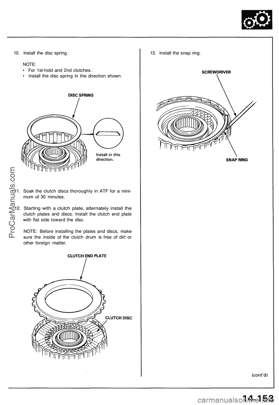
10. Install the disc spring.
NOTE:
• For 1st-hold and 2nd clutches.
• Install the disc spring in the direction shown.
13. Install the snap ring.
11. Soak the clutch discs thoroughly in ATF for a mini-
mum of 30 minutes.
12. Starting with a clutch plate, alternately install the
clutch plates and discs. Install the clutch end plate
with flat side toward the disc.
NOTE: Before installing the plates and discs, make
sure the inside of the clutch drum is free of dirt or
other foreign matter.ProCarManuals.com
Page 822 of 1503
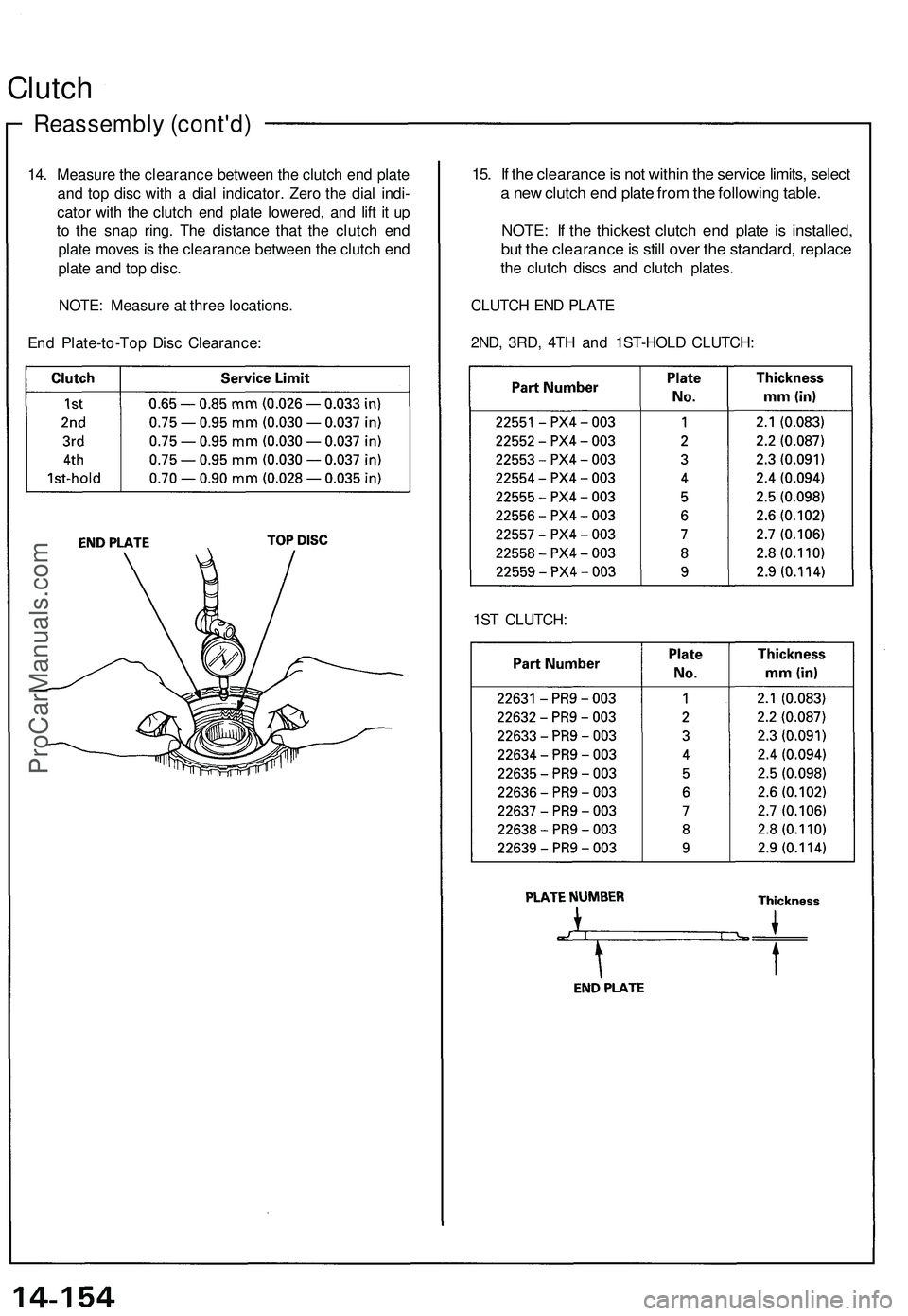
14. Measure the clearance between the clutch end plate
and top disc with a dial indicator. Zero the dial indi-
cator with the clutch end plate lowered, and lift it up
to the snap ring. The distance that the clutch end
plate moves is the clearance between the clutch end
plate and top disc.
NOTE: Measure at three locations.
End Plate-to-Top Disc Clearance:
Reassembly (cont'd)
Clutch
15. If the clearance is not within the service limits, select
a new clutch end plate from the following table.
NOTE: If the thickest clutch end plate is installed,
but the clearance is still over the standard, replace
the clutch discs and clutch plates.
CLUTCH END PLATE
2ND, 3RD, 4TH and 1ST-HOLD CLUTCH:
1ST CLUTCH:ProCarManuals.com
Page 823 of 1503
1st-hold Clutc h Bearin g
Replacemen t
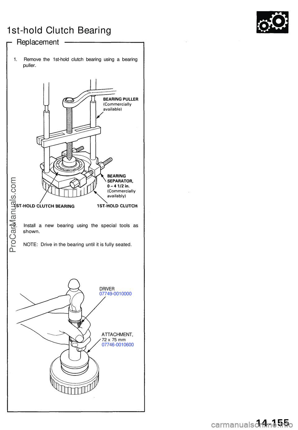
1. Remov e th e 1st-hol d clutc h bearin g usin g a bearin g
puller.
2. Instal l a ne w bearin g usin g th e specia l tool s a s
shown .
NOTE: Driv e in th e bearin g unti l i t i s full y seated .
DRIVER07749-001000 0
ATTACHMENT ,72 x 7 5 m m07746-001060 0
ProCarManuals.com
Page 824 of 1503
Torque Converter Housing Bearings
Mainshaft Bearing/Oil Seal Replacement
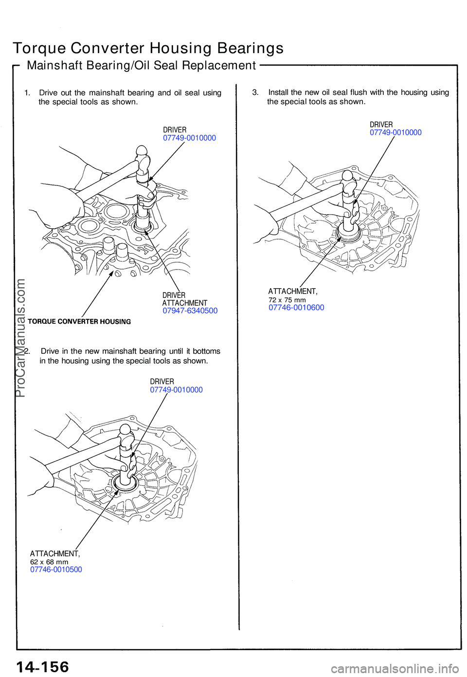
1. Driv e ou t th e mainshaf t bearin g an d oi l sea l usin g
th e specia l tool s a s shown .
DRIVER07749-001000 0
3. Instal l th e ne w oi l sea l flus h wit h th e housin g usin g
th e specia l tool s a s shown .
DRIVER07749-001000 0
DRIVERATTACHMEN T07947-634050 0
ATTACHMENT ,72 x 7 5 m m07746-001060 0
2 . Driv e in th e ne w mainshaf t bearin g unti l i t bottom s
i n th e housin g usin g th e specia l tool s a s shown .
DRIVER07749-001000 0
ATTACHMENT ,62 x 68 m m07746-001050 0
ProCarManuals.com
Page 825 of 1503
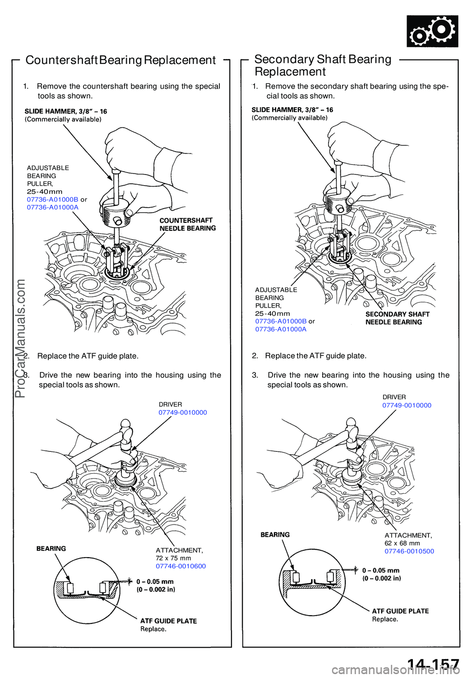
Countershaft Bearin g Replacemen t
1. Remov e th e countershaf t bearin g usin g th e specia l
tool s a s shown .
ADJUSTABL E
BEARIN G
PULLER ,
25 - 4 0 m m07736-A01000 B o r
07736-A01000 A
Secondary Shaf t Bearin g
Replacemen t
1. Remov e th e secondar y shaf t bearin g usin g th e spe -
cia l tool s a s shown .
ADJUSTABL E
BEARIN G
PULLER ,
25 - 4 0 m m07736-A01000 B o r
07736-A01000 A
2. Replac e th e AT F guid e plate .
3 . Driv e th e ne w bearin g int o th e housin g usin g th e
specia l tool s a s shown .
DRIVER07749-001000 0
2. Replac e th e AT F guid e plate .
3 . Driv e th e ne w bearin g int o th e housin g usin g th e
specia l tool s a s shown .
DRIVER07749-001000 0
ATTACHMENT ,72 x 75 m m07746-001060 0
ATTACHMENT ,62 x 68 m m07746-001050 0
ProCarManuals.com
Page 826 of 1503
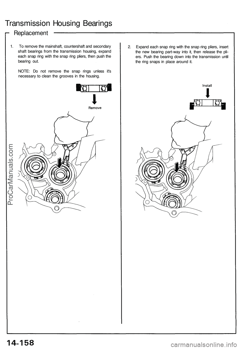
Replacement
Transmission Housin g Bearing s
1. T o remov e th e mainshaft , countershaf t an d secondar y
shaf t bearing s fro m th e transmissio n housing , expan d
eac h sna p rin g wit h th e sna p rin g pliers , the n pus h th e
bearin g out .
NOTE : D o no t remov e th e sna p ring s unles s it' s
necessar y t o clea n th e groove s i n th e housing . 2
. Expan d eac h sna p rin g wit h th e sna p rin g pliers , inser t
th e ne w bearin g part-wa y int o it , the n releas e th e pli -
ers . Pus h th e bearin g dow n int o th e transmissio n unti l
th e rin g snap s i n plac e aroun d it .
ProCarManuals.com
Page 827 of 1503
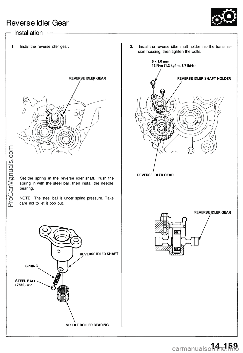
Reverse Idler Gear
Installation
1. Install the reverse idler gear.
3. Install the reverse idler shaft holder into the transmis-
sion housing, then tighten the bolts.
2. Set the spring in the reverse idler shaft. Push the
spring in with the steel ball, then install the needle
bearing.
NOTE: The steel ball is under spring pressure. Take
care not to let it pop out.ProCarManuals.com
Page 828 of 1503
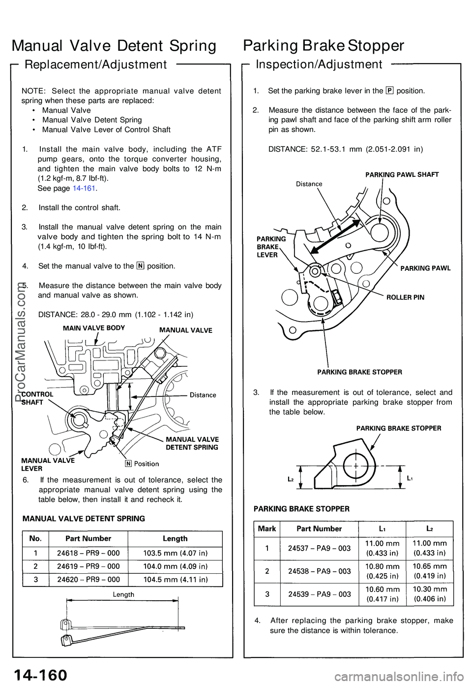
Replacement/Adjustment
Manual Valv e Deten t Sprin gParkin
g Brak e Stoppe r
Inspection/Adjustmen t
NOTE: Selec t th e appropriat e manua l valv e deten t
sprin g whe n thes e part s ar e replaced :
• Manua l Valv e
• Manua l Valv e Deten t Sprin g
• Manua l Valv e Leve r o f Contro l Shaf t
1 . Instal l th e mai n valv e body , includin g th e AT F
pum p gears , ont o th e torqu e converte r housing ,
an d tighte n th e mai n valv e bod y bolt s t o 1 2 N- m
(1. 2 kgf-m , 8. 7 Ibf-ft) .
Se e pag e 14-161 .
2 . Instal l th e contro l shaft .
3 . Instal l th e manua l valv e deten t sprin g o n th e mai n
valve bod y an d tighte n th e sprin g bol t t o 1 4 N- m
(1.4 kgf-m , 1 0 Ibf-ft) .
4. Se t th e manua l valv e t o th e position .
5 . Measur e th e distanc e betwee n th e mai n valv e bod y
an d manua l valv e a s shown .
DISTANCE : 28. 0 - 29. 0 m m (1.10 2 - 1.14 2 in )
1. Se t th e parkin g brak e leve r i n th e position .
2 . Measur e th e distanc e betwee n th e fac e o f th e park -
in g paw l shaf t an d fac e o f th e parkin g shif t ar m rolle r
pi n a s shown .
DISTANCE : 52.1-53. 1 m m (2.051-2.09 1 in )
6 . I f th e measuremen t i s ou t o f tolerance , selec t th e
appropriat e manua l valv e deten t sprin g usin g th e
tabl e below , the n instal l i t an d rechec k it . 3
. I f th e measuremen t i s ou t o f tolerance , selec t an d
instal l th e appropriat e parkin g brak e stoppe r fro m
th e tabl e below .
4 . Afte r replacin g th e parkin g brak e stopper , mak e
sur e th e distanc e i s withi n tolerance .
ProCarManuals.com
Page 829 of 1503
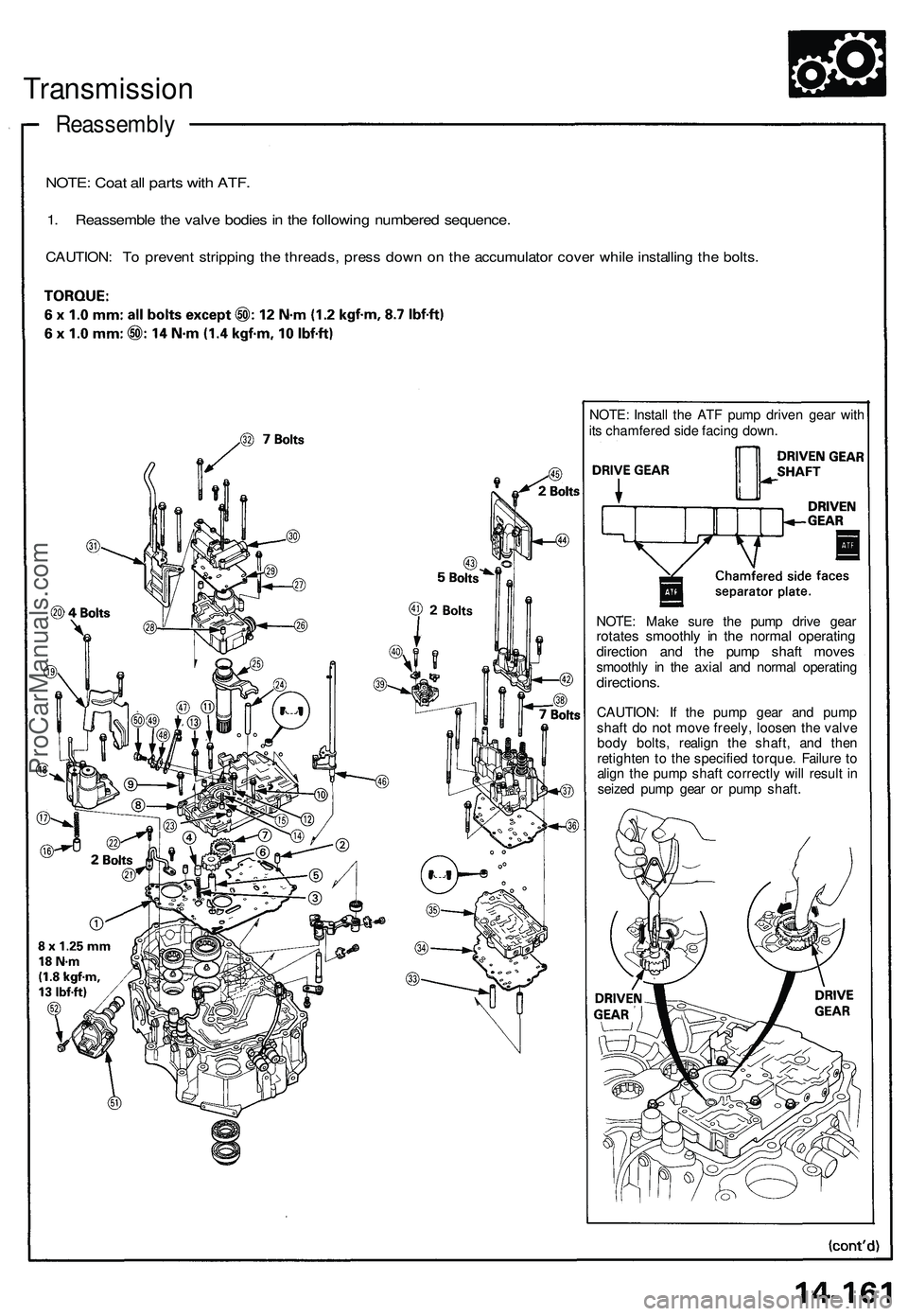
Reassembly
Transmissio n
NOTE: Coa t al l part s wit h ATF .
1. Reassembl e th e valv e bodie s in th e followin g numbere d sequence .
CAUTION: T o preven t strippin g th e threads , pres s dow n o n th e accumulato r cove r whil e installin g th e bolts .
NOTE : Instal l th e AT F pum p drive n gea r wit h
it s chamfere d sid e facin g down .
NOTE : Mak e sur e th e pum p driv e gea r
rotate s smoothl y i n th e norma l operatin gdirection an d th e pum p shaf t move ssmoothl y i n th e axia l an d norma l operatin gdirections .
CAUTION : I f th e pum p gea r an d pum p
shaf t d o no t mov e freely , loose n th e valv e
bod y bolts , realig n th e shaft , an d the n
retighte n t o th e specifie d torque . Failur e t o
alig n th e pum p shaf t correctl y wil l resul t i n
seize d pum p gea r o r pum p shaft .
ProCarManuals.com
Page 830 of 1503
Reassembly (cont'd )
Transmissio n
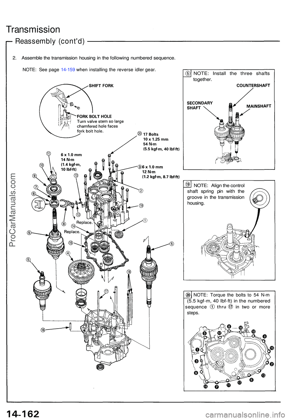
2. Assembl e th e transmissio n housin g in th e followin g numbere d sequence .
NOTE: Se e pag e 14-15 9 whe n installin g th e revers e idle r gear .NOTE : Instal l th e thre e shaft s
together .
NOTE : Alig n th e contro l
shaf t sprin g pi n wit h th e
groov e i n th e transmissio n
housing .
NOTE: Torqu e th e bolt s t o 5 4 N- m
(5.5 kgf-m , 4 0 Ibf-ft ) i n th e numbere d
sequence i n tw o o r mor e
steps.
ProCarManuals.com
Trending: towing, mirror, Brake pedal assembly, odometer, headrest, ECO mode, driver seat adjustment
