ACURA RL KA9 1996 Service Repair Manual
Manufacturer: ACURA, Model Year: 1996, Model line: RL KA9, Model: ACURA RL KA9 1996Pages: 1954, PDF Size: 61.44 MB
Page 1631 of 1954
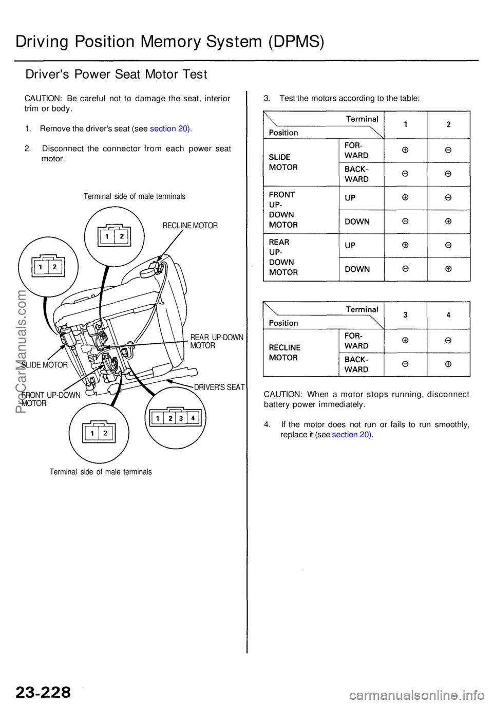
Driving Positio n Memor y Syste m (DPMS )
Driver's Powe r Sea t Moto r Tes t
CAUTION : B e carefu l no t t o damag e th e seat , interio r
tri m or body .
1 . Remov e th e driver' s sea t (se e sectio n 20 ).
2 . Disconnec t th e connecto r fro m eac h powe r sea t
motor .
Termina l sid e o f mal e terminal s
RECLIN E MOTO R
REAR UP-DOW NMOTOR
DRIVER' S SEA T
FRON T UP-DOW N
MOTOR
Termina l sid e o f mal e terminal s
SLID
E MOTO R
3. Tes t th e motor s accordin g t o th e table :
CAUTION : Whe n a moto r stop s running , disconnec t
batter y powe r immediately .
4 . I f th e moto r doe s no t ru n o r fail s t o ru n smoothly ,
replac e it (se e sectio n 20 ).
ProCarManuals.com
Page 1632 of 1954
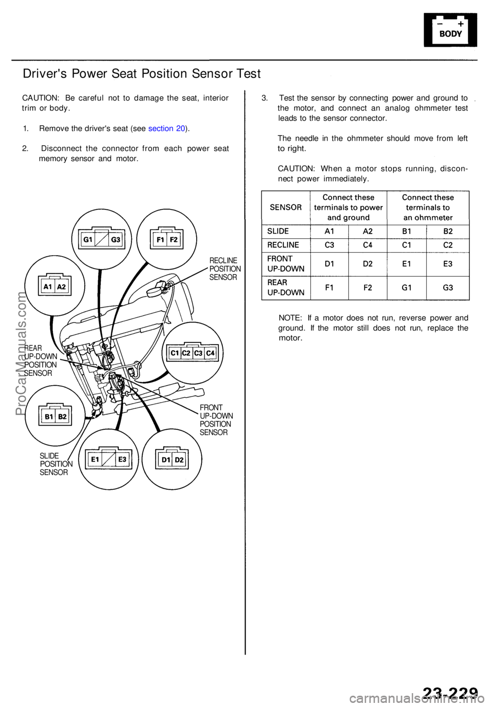
Driver's Powe r Sea t Positio n Senso r Tes t
CAUTION : B e carefu l no t t o damag e th e seat , interio r
tri m o r body .
1 . Remov e th e driver' s sea t (se e sectio n 20 ).
2 . Disconnec t th e connecto r fro m eac h powe r sea t
memor y senso r an d motor .
RECLIN EPOSITIO NSENSOR
REARUP-DOW NPOSITIONSENSOR
FRONT
UP-DOW N
POSITIO N
SENSOR
SLIDEPOSITIO NSENSOR
NOTE: I f a moto r doe s no t run , revers e powe r an d
ground . I f th e moto r stil l doe s no t run , replac e th e
motor .
3. Tes t th e senso r b y connectin g powe r an d groun d t o
th e motor , an d connec t a n analo g ohmmete r tes t
lead s t o th e senso r connector .
Th e needl e i n th e ohmmete r shoul d mov e fro m lef t
to right .
CAUTION : Whe n a moto r stop s running , discon -
nec t powe r immediately .
ProCarManuals.com
Page 1633 of 1954
Driving Positio n Memor y Syste m (DPMS )
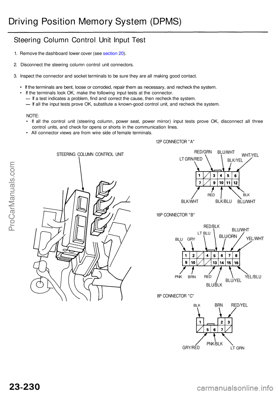
Steering Colum n Contro l Uni t Inpu t Tes t
1. Remov e th e dashboar d lowe r cove r (se e sectio n 20 ).
2 . Disconnec t th e steerin g colum n contro l uni t connectors .
3 . Inspec t th e connecto r an d socke t terminal s t o b e sur e the y ar e al l makin g goo d contact .
• I f th e terminal s ar e bent , loos e o r corroded , repai r the m as necessary , an d rechec k th e system .
• I f th e terminal s loo k OK , mak e th e followin g inpu t test s a t th e connector .
I f a tes t indicate s a problem , fin d an d correc t th e cause , the n rechec k th e system .
If al l th e inpu t test s prov e OK , substitut e a known-goo d contro l unit , an d rechec k th e system .
NOTE:
• I f al l th e contro l uni t (steerin g column , powe r seat , powe r mirror ) inpu t test s prov e OK , disconnec t al l thre e
contro l units , an d chec k fo r open s o r short s i n th e communicatio n lines .
• Al l connecto r view s ar e fro m wir e sid e o f femal e terminals .
STEERING COLUM N CONTRO L UNI T 12
P CONNECTO R "A "
BLK/WH T
BLK/BLUBLU/WH T
BLKRE D
WHT/YE L
RED/GR
N
BLU/WH T
BLK/YELLT GRN/RE D
16 P CONNECTO R "B "
BLUGR Y
LT BL U
RED/BL K
BLU/ORN
BLU/WH T
YEL/WHT
YEL/BLUBLU/YE LBLU/BLK
REDBR NPNK
8P CONNECTO R "C "
BLKBR N RED/YE L
LT GR NPNK/BL KGRY/RED
ProCarManuals.com
Page 1634 of 1954
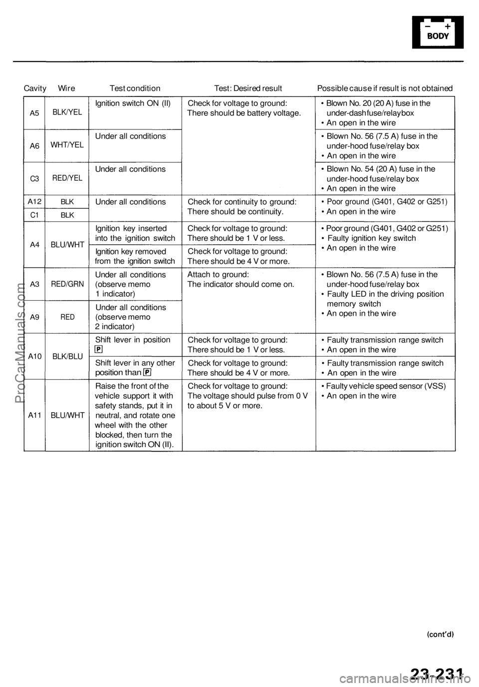
Cavity Wir e Test conditio n Test: Desire d resul t Possible caus e if resul t i s no t obtaine d
A5
A6
C 3
A1 2
C1
A4
A3
A 9
A1 0
A1 1
BLK/YE L
WHT/YE L
RED/YEL
BLK
BLK
BLU/WH T
RED/GR N
RED
BLK/BL U
BLU/WH T
Ignition switc h O N (II )
Unde r al l condition s
Unde r al l condition s
Unde r al l condition s
Ignitio n ke y inserte d
int o th e ignitio n switc h
Ignitio n ke y remove d
fro m th e ignitio n switc h
Unde r al l condition s
(observ e mem o
1 indicator )
Unde r al l condition s
(observ e mem o
2 indicator )
Shif t leve r i n positio n
Shift leve r i n an y othe r
positio n tha n
Rais e th e fron t o f th e
vehicl e suppor t i t wit h
safet y stands , pu t i t i n
neutral , an d rotat e on e
whee l wit h th e othe r
blocked , the n tur n th e
ignitio n switc h O N (II) .
Chec k fo r voltag e to ground :
Ther e shoul d b e batter y voltage .
Chec k fo r continuit y t o ground :
Ther e shoul d b e continuity .
Chec k fo r voltag e to ground :
Ther e shoul d b e 1 V or less .
Chec k fo r voltag e to ground :
Ther e shoul d b e 4 V or more .
Attac h t o ground :
Th e indicato r shoul d com e on .
Chec k fo r voltag e to ground :
Ther e shoul d b e 1 V or less .
Chec k fo r voltag e to ground :
Ther e shoul d b e 4 V or more .
Chec k fo r voltag e to ground :
Th e voltag e shoul d puls e fro m 0 V
t o abou t 5 V or more . •
Blow n No . 2 0 (2 0 A ) fus e in th e
under-das h fuse/rela y bo x
• A n ope n in th e wir e
• Blow n No . 5 6 (7. 5 A ) fus e in th e
under-hoo d fuse/rela y bo x
• A n ope n in th e wir e
• Blow n No . 5 4 (2 0 A ) fus e in th e
under-hoo d fuse/rela y bo x
• A n ope n in th e wir e
• Poo r groun d (G401 , G40 2 o r G251 )
• A n ope n in th e wir e
• Poo r groun d (G401 , G40 2 o r G251 )
• Fault y ignitio n ke y switc h
• A n ope n in th e wir e
• Blow n No . 5 6 (7. 5 A ) fus e in th e
under-hoo d fuse/rela y bo x
• Fault y LE D in th e drivin g positio n
memor y switc h
• A n ope n in th e wir e
• Fault y transmissio n rang e switc h
• A n ope n in th e wir e
• Fault y transmissio n rang e switc h
• A n ope n in th e wir e
• Fault y vehicl e spee d senso r (VSS )
• A n ope n in th e wir e
ProCarManuals.com
Page 1635 of 1954
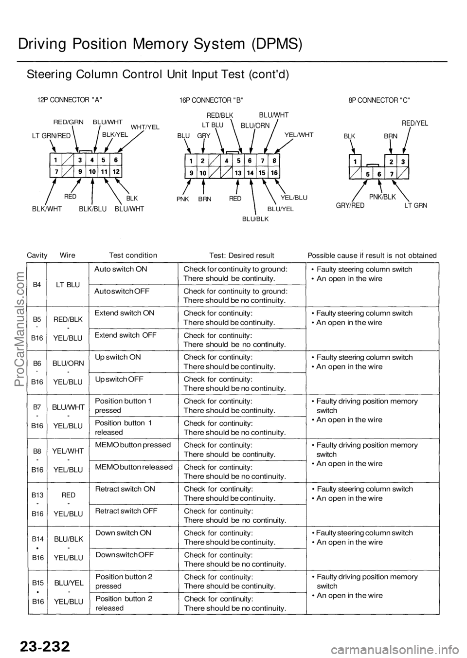
Driving Positio n Memor y Syste m (DPMS )
Steering Colum n Contro l Uni t Inpu t Tes t (cont'd )
12P CONNECTO R "A "
RED/GR N BLU/WH TWHT/YELBLK/YEL
PNK BR NREDYEL/BL U
BLU/YE L
BLU/BLK
8P CONNECTO R "C "
RED/YE L
BLKBR N
GRY/RE DLT GR N
Cavit y Wir eTest conditio nTest: Desire d resul tPossibl e caus e if resul t i s no t obtaine d
B4
B5*
B1 6
B6*
B1 6
B7•
B1 6
B8•
B1 6
B1 3•
B16
B1 4
B16
B15
B16
LT BL U
RED/BL K•
YEL/BLU
BLU/OR N•
YEL/BLU
BLU/WH T•
YEL/BLU
YEL/WH T•
YEL/BLU
RED•
YEL/BL U
BLU/BL K•
YEL/BL U
BLU/YEL•
YEL/BLU
Auto switc h O N
Aut o switc h OF F
Exten d switc h O N
Exten d switc h OF F
Up switc h O N
U p switc h OF F
Positio n butto n 1
presse d
Position butto n 1
release d
MEMO butto n presse d
MEM O butto n release d
Retrac t switc h O N
Retrac t switc h OF F
Dow n switc h O N
Dow n switc h OF F
Positio n butto n 2
presse d
Position butto n 2
release d
Check fo r continuit y to ground :
Ther e shoul d b e continuity .
Check fo r continuit y t o ground :
There shoul d b e n o continuity .
Chec k fo r continuity :
Ther e shoul d b e continuity .
Check fo r continuity :
There shoul d b e n o continuity .
Chec k fo r continuity :
Ther e shoul d b e continuity .
Check fo r continuity :
There shoul d b e n o continuity .
Check fo r continuity :
There shoul d b e continuity .
Chec k fo r continuity :
Ther e shoul d b e n o continuity .
Check fo r continuity :
There shoul d b e continuity .
Check fo r continuity :
There shoul d b e n o continuity .
Chec k fo r continuity :
Ther e shoul d b e continuity .
Check fo r continuity :
There shoul d b e n o continuity .
Check fo r continuity :
There shoul d b e continuity .
Check fo r continuity :
There shoul d b e n o continuity .
Check fo r continuity :
There shoul d b e continuity .
Chec k fo r continuity :
Ther e shoul d b e n o continuity .
• Fault y steerin g colum n switc h
• A n ope n in th e wir e
• Fault y steerin g colum n switc h
• A n ope n in th e wir e
• Fault y steerin g colum n switc h
• A n ope n in th e wir e
• Fault y drivin g positio n memor y
switch
• A n ope n in th e wir e
• Fault y drivin g positio n memor y
switc h
• A n ope n in th e wir e
• Fault y steerin g colum n switc h
• A n ope n in th e wir e
• Fault y steerin g colum n switc h
• A n ope n in th e wir e
• Fault y drivin g positio n memor y
switch
• A n ope n in th e wir e
16P CONNECTO R "B "
RED/BL K
BLU GR Y
LT BL UBLU/OR N
BLU/WH
T
YEL/WHT
PNK/BLK
BLK/WH T BLK/BL U BLU/WH TBLKRE D
LT GRN/RE D
ProCarManuals.com
Page 1636 of 1954
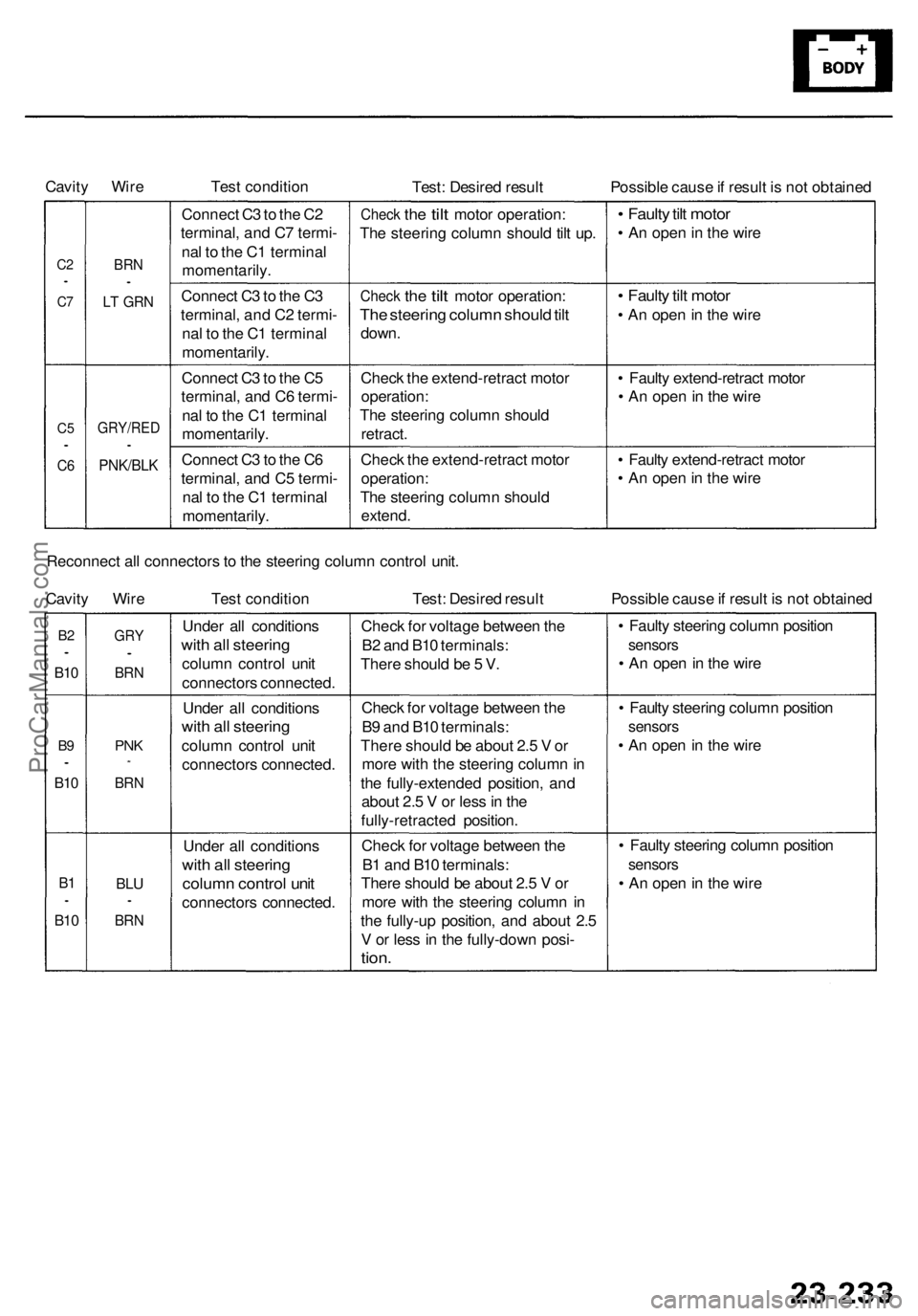
Cavity Wire
Test condition
Test: Desired result
Possible cause if result is not obtained
C2
•
C7
C5
•
C6
BRN
•
LT GRN
GRY/RED
•
PNK/BLK
Connect C3 to the C2
terminal, and C7 termi-
nal to the C1 terminal
momentarily.
Connect C3 to the C3
terminal, and C2 termi-
nal to the C1 terminal
momentarily.
Connect C3 to the C5
terminal, and C6 termi-
nal to the C1 terminal
momentarily.
Connect C3 to the C6
terminal, and C5 termi-
nal to the C1 terminal
momentarily.
Check
the
tilt
motor operation:
The steering column should tilt up.
Check
the
tilt
motor operation:
The steering column should tilt
down.
Check the extend-retract motor
operation:
The steering column should
retract.
Check the extend-retract motor
operation:
The steering column should
extend.
• Faulty tilt motor
• An open in the wire
• Faulty tilt motor
• An open in the wire
• Faulty extend-retract motor
• An open in the wire
• Faulty extend-retract motor
• An open in the wire
Reconnect all connectors to the steering column control unit.
Cavity Wire
Test condition
Test: Desired result
Possible cause if result is not obtained
B2
•
B10
B9
•
B10
B1
•
B10
GRY
•
BRN
PNK
*
BRN
BLU
•
BRN
Under all conditions
with all steering
column control unit
connectors connected.
Under all conditions
with all steering
column control unit
connectors connected.
Under all conditions
with all steering
column control unit
connectors connected.
Check for voltage between the
B2 and B10 terminals:
There should be 5 V.
Check for voltage between the
B9 and B10 terminals:
There should be about 2.5 V or
more with the steering column in
the fully-extended position, and
about 2.5 V or less in the
fully-retracted position.
Check for voltage between the
B1 and B10 terminals:
There should be about 2.5 V or
more with the steering column in
the fully-up position, and about 2.5
V or less in the fully-down posi-
tion.
• Faulty steering column position
sensors
• An open in the wire
• Faulty steering column position
sensors
• An open in the wire
• Faulty steering column position
sensors
• An open in the wireProCarManuals.com
Page 1637 of 1954
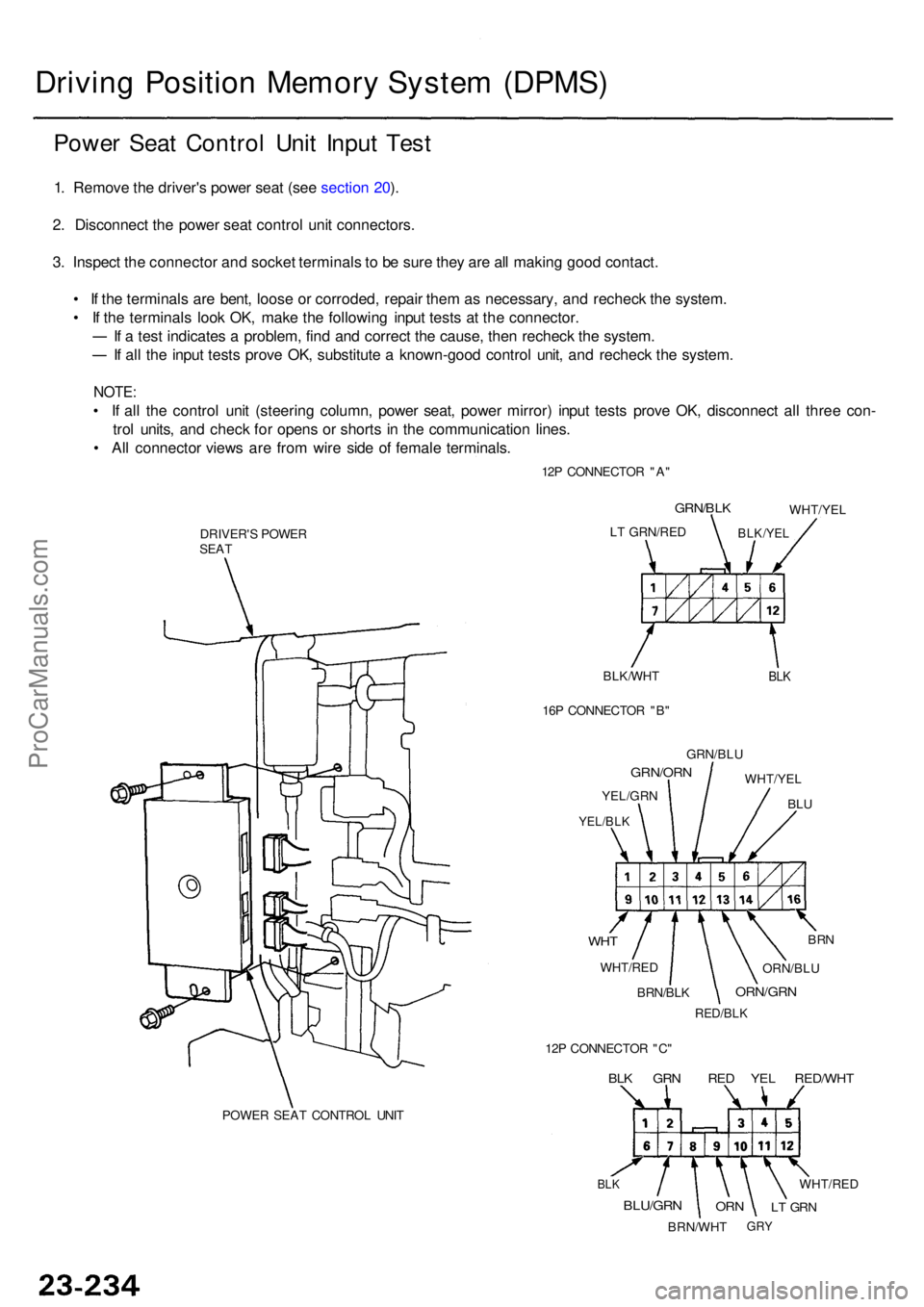
Driving Positio n Memor y Syste m (DPMS )
Power Sea t Contro l Uni t Inpu t Tes t
1. Remov e th e driver' s powe r sea t (se e sectio n 20 ).
2 . Disconnec t th e powe r sea t contro l uni t connectors .
3 . Inspec t th e connecto r an d socke t terminal s t o b e sur e the y ar e al l makin g goo d contact .
• I f th e terminal s ar e bent , loos e o r corroded , repai r the m a s necessary , an d rechec k th e system .
• I f th e terminal s loo k OK , mak e th e followin g inpu t test s a t th e connector .
I f a tes t indicate s a problem , fin d an d correc t th e cause , the n rechec k th e system .
If al l th e inpu t test s prov e OK , substitut e a known-goo d contro l unit , an d rechec k th e system .
NOTE:
• I f al l th e contro l uni t (steerin g column , powe r seat , powe r mirror ) inpu t test s prov e OK , disconnec t al l thre e con -
tro l units , an d chec k fo r open s o r short s i n th e communicatio n lines .
• Al l connecto r view s ar e fro m wir e sid e o f femal e terminals .
12P CONNECTO R "A "
POWE R SEA T CONTRO L UNI T
DRIVER'
S POWE R
SEA T
BLK/WHT
BLK
LT GRN/RE D
GRN/BLK
BLK/YE L
WHT/YE L
16 P CONNECTO R "B "
GRN/BL U
WHT/YE L
BLU
GRN/OR N
YEL/GRN
YEL/BLK
WHT
WHT/RE D
BRN
ORN/BL U
ORN/GR N
RED/BLK
BRN/BLK
12 P CONNECTO R "C "
BLK GR N RE D YE L RED/WH T
BLK
BLU/GR N
BRN/WH T
ORNLT GR N
WHT/RE D
GRY
ProCarManuals.com
Page 1638 of 1954
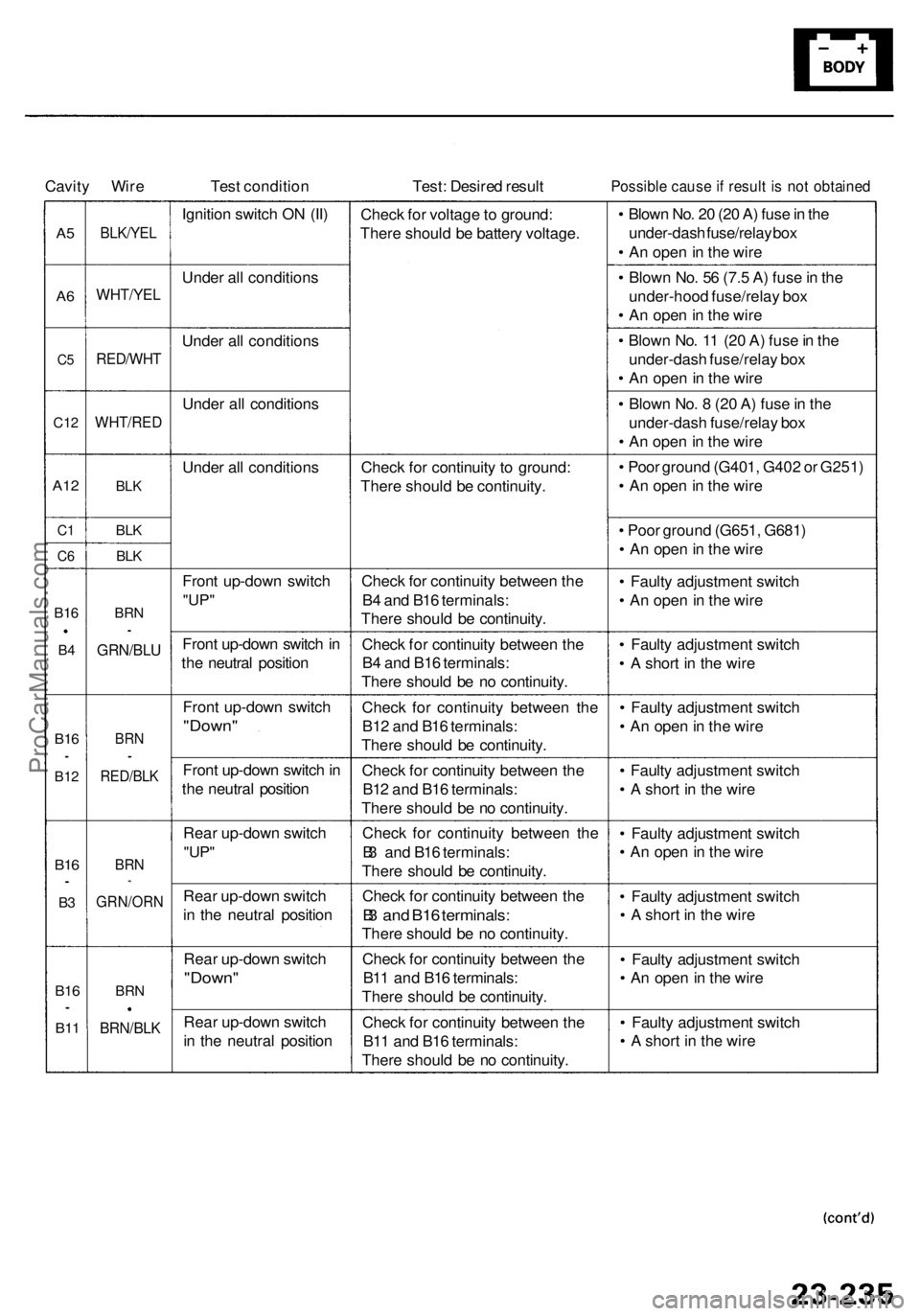
Cavity Wir e Test conditio n Test: Desire d resul tPossibl e caus e if resul t i s no t obtaine d
A5
A 6
C 5
C1 2
A12
C1
C 6
B1 6
B4
B1 6•
B1 2
B16•
B3
B1 6•
B11
BLK/YE L
WHT/YE L
RED/WH T
WHT/RED
BLK
BLK
BLK
BR N•
GRN/BL U
BRN•
RED/BL K
BRN*
GRN/OR N
BRN
BRN/BL K
Ignition switc h O N (II )
Unde r al l condition s
Unde r al l condition s
Unde r al l condition s
Unde r al l condition s
Fron t up-dow n switc h
"UP"
Fron t up-dow n switc h in
th e neutra l positio n
Fron t up-dow n switc h
"Down "
Front up-dow n switc h in
th e neutra l positio n
Rea r up-dow n switc h
"UP"
Rea r up-dow n switc h
i n th e neutra l positio n
Rea r up-dow n switc h
"Down "
Rear up-dow n switc h
i n th e neutra l positio nChec
k fo r voltag e to ground :
Ther e shoul d b e batter y voltage .
Chec k fo r continuit y t o ground :
Ther e shoul d b e continuity .
Chec k fo r continuit y betwee n th e
B 4 an d B1 6 terminals :
Ther e shoul d b e continuity .
Chec k fo r continuit y betwee n th e
B 4 an d B1 6 terminals :
Ther e shoul d b e n o continuity .
Chec k fo r continuit y betwee n th e
B1 2 an d B1 6 terminals :
Ther e shoul d b e continuity .
Chec k fo r continuit y betwee n th e
B1 2 an d B1 6 terminals :
Ther e shoul d b e n o continuity .
Chec k fo r continuit y betwee n th e
B 3 an d B1 6 terminals :
Ther e shoul d b e continuity .
Chec k fo r continuit y betwee n th e
B3 an d B1 6 terminals :
There shoul d b e n o continuity .
Chec k fo r continuit y betwee n th e
B1 1 an d B1 6 terminals :
Ther e shoul d b e continuity .
Chec k fo r continuit y betwee n th e
B1 1 an d B1 6 terminals :
Ther e shoul d b e n o continuity .•
Blow n No . 2 0 (2 0 A ) fus e in th e
under-das h fuse/rela y bo x
• A n ope n in th e wir e
• Blow n No . 5 6 (7. 5 A ) fus e in th e
under-hoo d fuse/rela y bo x
• A n ope n in th e wir e
• Blow n No . 1 1 (2 0 A ) fus e in th e
under-das h fuse/rela y bo x
• A n ope n in th e wir e
• Blow n No . 8 (2 0 A ) fus e in th e
under-das h fuse/rela y bo x
• A n ope n in th e wir e
• Poo r groun d (G401 , G40 2 o r G251 )
• A n ope n in th e wir e
• Poo r groun d (G651 , G681 )
• A n ope n in th e wir e
• Fault y adjustmen t switc h
• A n ope n in th e wir e
• Fault y adjustmen t switc h
• A shor t i n th e wir e
• Fault y adjustmen t switc h
• A n ope n in th e wir e
• Fault y adjustmen t switc h
• A shor t i n th e wir e
• Fault y adjustmen t switc h
• A n ope n in th e wir e
• Fault y adjustmen t switc h
• A shor t i n th e wir e
• Fault y adjustmen t switc h
• A n ope n in th e wir e
• Fault y adjustmen t switc h
• A shor t i n th e wir e
ProCarManuals.com
Page 1639 of 1954
Driving Positio n Memor y Syste m (DPMS )
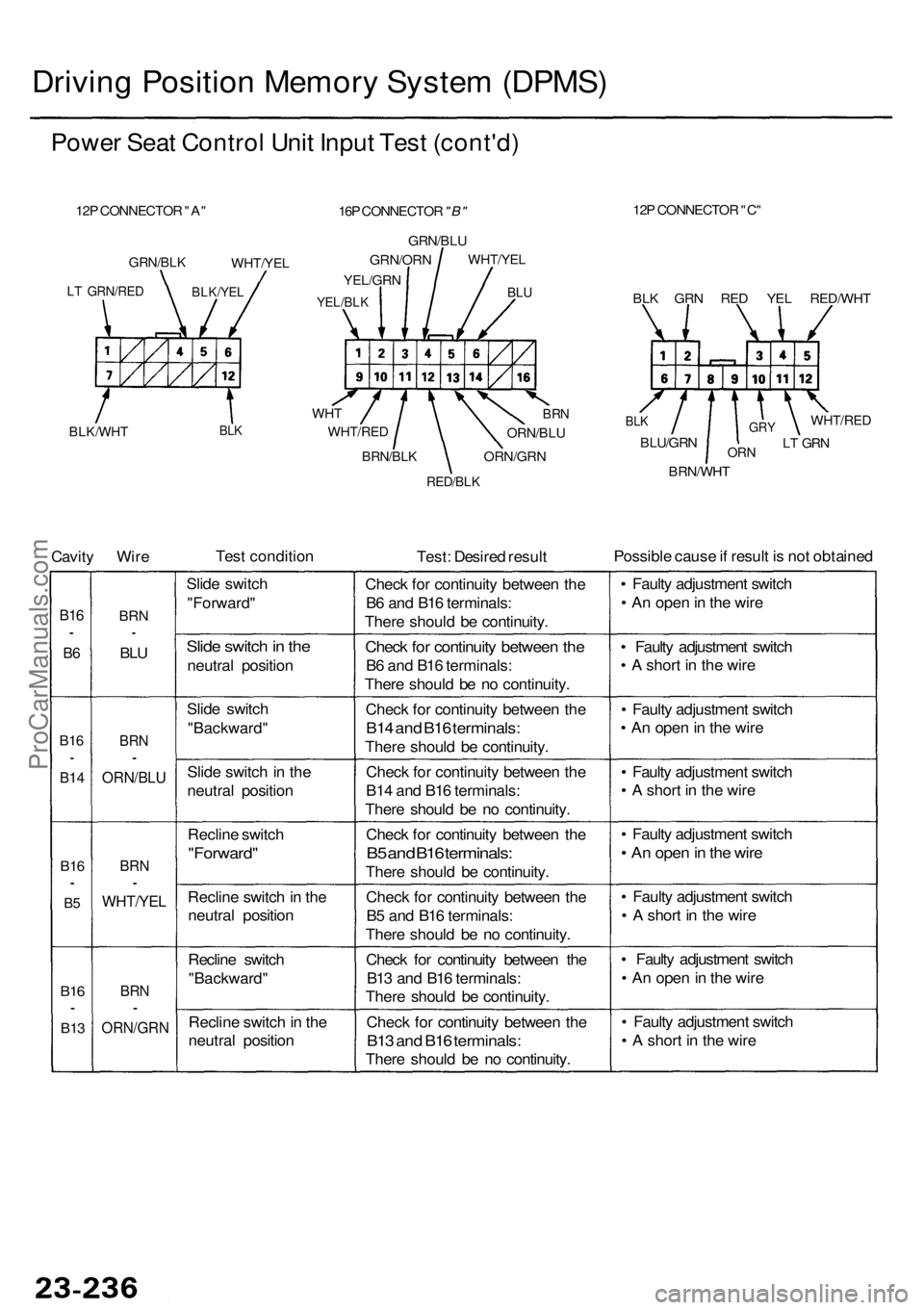
Power Sea t Contro l Uni t Inpu t Tes t (cont'd )
12P CONNECTO R "A "
BLK/WH TBLK
12P CONNECTO R "C "
BLU
WH T
WHT/RE D
Cavity Wir e Tes
t conditio n
Test: Desire d resul t Possibl
e caus e if resul t i s no t obtaine d
B16•
B6
B1 6•
B1 4
B16•
B5
B1 6•
B1 3
BR N•
BLU
BR N•
ORN/BL U
BRN•
WHT/YE L
BRN•
ORN/GR N
Slide switc h
"Forward "
Slide switc h in th e
neutra l positio n
Slid e switc h
"Backward "
Slid e switc h in th e
neutra l positio n
Reclin e switc h
"Forward "
Recline switc h in th e
neutra l positio n
Reclin e switc h
"Backward "
Reclin e switc h in th e
neutra l positio n Chec
k fo r continuit y betwee n th e
B 6 an d B1 6 terminals :
Ther e shoul d b e continuity .
Check fo r continuit y betwee n th e
B6 an d B1 6 terminals :
Ther e shoul d b e n o continuity .
Chec k fo r continuit y betwee n th e
B14 an d B1 6 terminals :
There shoul d b e continuity .
Chec k fo r continuit y betwee n th e
B1 4 an d B1 6 terminals :
Ther e shoul d b e n o continuity .
Chec k fo r continuit y betwee n th e
B5 an d B1 6 terminals :
There shoul d b e continuity .
Chec k fo r continuit y betwee n th e
B 5 an d B1 6 terminals :
Ther e shoul d b e n o continuity .
Chec k fo r continuit y betwee n th e
B1 3 an d B1 6 terminals :
Ther e shoul d b e continuity .
Chec k fo r continuit y betwee n th e
B13 an d B1 6 terminals :
There shoul d b e n o continuity .•
Fault y adjustmen t switc h
• A n ope n in th e wir e
• Fault y adjustmen t switc h
• A shor t i n th e wir e
• Fault y adjustmen t switc h
• A n ope n in th e wir e
• Fault y adjustmen t switc h
• A shor t i n th e wir e
• Fault y adjustmen t switc h
• A n ope n in th e wir e
• Fault y adjustmen t switc h
• A shor t i n th e wir e
• Fault y adjustmen t switc h
• A n ope n in th e wir e
• Fault y adjustmen t switc h
• A shor t i n th e wir e
BRN/BL K
RED/BLK
ORN/GR N
ORN/BLU
BRN
GRN/BL K
LT GRN/RE DBLK/YEL
WHT/YE L
16P CONNECTO R "B"
GRN/BL U
WHT/YE LGRN/OR N
YEL/GRN
YEL/BLKBLK GR N RE D YE L RED/WH T
BLK
BLU/GR N
BRN/WH TORN
GR YLT GR N
WHT/RE D
ProCarManuals.com
Page 1640 of 1954
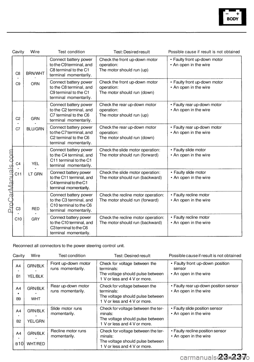
Cavity Wir eTest conditio nTest: Desire d resul tPossibl e caus e if resul t i s no t obtaine d
C8•
C9
C 2•
C7
C 4•
C1 1
C3•
C1 0
BRN/WH T*
ORN
GR N•
BLU/GR N
YEL•
LT GR N
RED•
GR Y
Connec t batter y powe r
to th e C 9 terminal , an d
C8 termina l t o th e C 1
termina l momentarily .
Connec t batter y powe r
t o th e C 8 terminal , an d
C 9 termina l t o th e C 1
termina l momentarily .
Connec t batter y powe r
t o th e C 2 terminal , an d
C 7 termina l t o th e C 6
termina l momentarily .
Connec t batter y powe r
to th e C 7 terminal , an d
C2 termina l t o th e C 6
termina l momentarily .
Connec t batter y powe r
t o th e C 4 terminal , an d
C1 1 termina l t o th e C 1
termina l momentarily .
Connec t batter y powe r
t o th e C1 1 terminal , an d
C4 termina l t o th e C 1
termina l momentarily .
Connect batter y powe r
t o th e C 3 terminal , an d
C1 0 termina l t o th e C 6
termina l momentarily .
Connec t batter y powe r
t o th e C1 0 terminal , an d
C 3 termina l t o th e C 6
termina l momentarily .Chec
k th e fron t up-dow n moto r
operation :
Th e moto r shoul d ru n (up )
Chec k th e fron t up-dow n moto r
operation :
Th e moto r shoul d ru n (down )
Chec k th e rea r up-dow n moto r
operation :
Th e moto r shoul d ru n (up )
Chec k th e rea r up-dow n moto r
operation :
Th e moto r shoul d ru n (down )
Chec k th e slid e moto r operation :
Th e moto r shoul d ru n (forward )
Chec k th e slid e moto r operation :
Th e moto r shoul d ru n (backward )
Chec k th e reclin e moto r operation :
Th e moto r shoul d ru n (forward )
Chec k th e reclin e moto r operation :
Th e moto r shoul d ru n (backward )•
Fault y fron t up-dow n moto r
• A n ope n in th e wir e
• Fault y fron t up-dow n moto r
• A n ope n in th e wir e
• Fault y rea r up-dow n moto r
• A n ope n in th e wir e
• Fault y rea r up-dow n moto r
• A n ope n in th e wir e
• Fault y slid e moto r
• A n ope n in th e wir e
• Fault y slid e moto r
• A n ope n in th e wir e
• Fault y reclin e moto r
• A n ope n in th e wir e
• Fault y reclin e moto r
• A n ope n in th e wir e
Reconnec t al l connector s to th e powe r steerin g contro l unit .
Cavit y Wir e Test conditio n
Test: Desire d resul t Possibl
e caus e if resul t i s no t obtaine d
A4•
B1
A 4
B9
A 4•
B2
A 4•
B 10
GRN/BL K•
YEL/BLK
GRN/BL K•
WHT
GRN/BL K•
YEL/GRN
GRN/BLK•
WHT/RE D
Front up-dow n moto r
runs momentarily .
Rea r up-dow n moto r
run s momentarily .
Slid e moto r run s
momentarily .
Reclin e moto r run s
momentarily . Chec
k fo r voltag e betwee n th e
terminals :
Th e voltag e shoul d puls e betwee n
1 V or les s an d 4 V or more .
Chec k fo r voltag e betwee n th e
terminals :
Th e voltag e shoul d puls e betwee n
1 V or les s an d 4 V or more .
Chec k fo r voltag e betwee n th e ter -
minals :
Th e voltag e shoul d puls e betwee n
1 V or les s an d 4 V or more .
Chec k fo r voltag e betwee n th e ter -
minals :
Th e voltag e shoul d puls e betwee n
1 V or les s an d 4 V or more .
• Fault y fron t up-dow n positio n
sensor
• A n ope n in th e wir e
• Fault y rea r up-dow n positio n senso r
• A n ope n in th e wir e
• Fault y slid e positio n senso r
• A n ope n in th e wir e
• Fault y reclin e positio n senso r
• A n ope n in th e wir e
ProCarManuals.com