ACURA RL KA9 1996 Service Repair Manual
Manufacturer: ACURA, Model Year: 1996, Model line: RL KA9, Model: ACURA RL KA9 1996Pages: 1954, PDF Size: 61.44 MB
Page 1601 of 1954

Descriptio n
The driver' s seat , th e powe r mirror s an d th e steerin g column , whos e position s ar e determine d th e driver' s position , hav e")
Driving Positio n Memor y Syste m (DPMS )
Descriptio n
The driver' s seat , th e powe r mirror s an d th e steerin g column , whos e position s ar e determine d th e driver' s position , hav e
a memor y feature . Th e sea t adjustments , th e mirro r adjustments , an d th e steerin g colum n adjustment s can be regulate d
separately . Al l o f adjustment s ca n b e memorize d b y th e pressin g th e MEM O butto n o n th e drivin g positio n memor y
switch , an d the n pressin g on e o f th e tw o positio n button s withi n 5 seconds . Pressin g th e appropriat e positio n butto n wil l
mov e th e seat , th e mirro r an d th e steerin g colum n t o th e positio n memorize d fo r drive r 1 o r drive r 2 , eliminatin g manua l
adjustment s whe n changin g drivers .
NOTE : Disconnectin g th e batter y wil l cance l th e memorize d positions .
STEERIN G COLUM N POSITIO N SENSOR S
B y mean s o f th e variabl e resistor-typ e til t positio n senso r an d extend-retrac t positio n sensor , th e steerin g colum n contro l
uni t detect s th e voltag e change s cause d b y th e movement s o f th e steerin g column . Thes e voltag e change s ar e store d in
memory , an d th e steerin g colum n positio n is memorized .
POWE R SEA T POSITIO N SENSOR S
Eac h moto r ha s a ree d switc h senso r whic h detect s moto r rotatio n an d send s a puls e to th e powe r sea t contro l uni t whe n
th e moto r rotates . Th e contro l uni t store s th e numbe r o f pulse s i n it s memory , an d th e sea t positio n is memorized .
POWE R MIRRO R POSITIO N SENSOR S
B y mean s o f a Hall-effec t typ e til t positio n senso r an d swin g positio n sensor , th e powe r mirro r contro l uni t detect s th e
voltag e change s cause d b y th e movement s o f th e mirrors .
Thes e voltag e change s ar e store d in memory , an d th e powe r mirro r position s ar e memorized .
"AUTO " SWITC H FUNCTIO N
Whe n th e ignitio n ke y i s pulle d ou t (ignitio n switc h turne d OFF ) wit h th e AUT O switc h i n th e steerin g colum n switc h O N
and th e vehicl e parke d (shif t leve r i n th e steerin g colum n wil l automaticall y mov e t o th e highes t til t positio n an d full y
retracte d positio n t o eas e exi t fro m th e vehicle .
Whe n th e ignitio n ke y i s inserte d int o th e ignitio n ke y switc h wit h th e AUT O switc h O N an d th e vehicl e parke d (shif t leve r
in th e steerin g colum n wil l automaticall y mov e bac k t o th e previou s position .
MEMOR Y RETRIEV E
When on e o f th e tw o button s o n th e drivin g positio n memor y switc h i s presse d wit h th e vehicl e parke d (shif t leve r i n
th e seat , th e mirror , an d th e steerin g colum n mov e t o th e memorize d positions .
ProCarManuals.com
Page 1602 of 1954

MEMORY RANGE S
Sea t an d steerin g colum n position s ca n b e memorize d withi n thes e ranges :
NOTE: Th e powe r mirro r positio n ca n b e memorize d withi n al l range s o f th e mirro r movements .
Power Seat :NEUTRA L
Steering Column :
240 m m(9. 4 in)
40 m m(1.6 in )
RETRAC T
EXTEND
TIL
T DOW N
TIL
T U P
30 m m (1. 2 in)
ProCarManuals.com
Page 1603 of 1954

Self-diagnosti c Procedure s
The self-diagnosti c functio n o f th e drivin g positio n memor y syste m detect s syste m problems , an d store s u p t o 5 pr")
Driving Positio n Memor y Syste m (DPMS )
Self-diagnosti c Procedure s
The self-diagnosti c functio n o f th e drivin g positio n memor y syste m detect s syste m problems , an d store s u p t o 5 proble m
cause s i n memory . This informatio n ca n b e retrieve d b y displayin g th e diagnosti c troubl e code .
Displayin g th e Diagnosti c Troubl e Cod e (DTC )
1 . Tur n th e ignitio n switc h OFF .
2 . Pres s th e MEM O butto n an d bot h positio n button s
a t th e sam e time , an d hol d them .
3 . Tur n th e ignitio n switc h O N (II) , an d wai t a t leas t
1 second , the n releas e th e thre e buttons .
4. Afte r 1 second , th e positio n butto n indicator s wil l
blin k t o sho w th e DTC .
DT C Indication s
N o Syste m Problem :
I f ther e is n o DT C stored , th e indicator s blin k onl y onc e ( 3 seconds) .INDICATOR S (LED )
Indicato r 1
indicato r 2
Ignitio n
switc h
MEM O butto nPos. butto n 1
Pos . butto n 2
Syste m Problem(s ) Exist(s ) (Exampl e show s DT C 12) :
U p t o fiv e DTC s ca n b e indicate d i n th e orde r th e problem s occurred . Th e firs t digi t i s indicate d b y th e numbe r o f lon g
( 1 second ) blinks , an d th e secon d digi t i s indicate d b y th e numbe r o f shor t (0.2 6 second ) blinks . Ther e i s a 3 secon d brea k
betwee n eac h DT C whe n ther e ar e multipl e DTCs .
MEM O butto n
Pos. butto n 1Pos . butto n 2
Ignitio n switc h
Indicato r 1
Indicato r 2
Cancellin g th e DT C Indicatio n
• Tur n th e ignitio n switc h OF F o r
• Pres s th e MEM O button , o r th e positio n butto n 1 , o r th e positio n butto n 2 , o r
• Pres s on e o f th e drivin g positio n adjustmen t switches .
Erasin g th e DT C fro m Memor y
NOTE:
• Th e PC M memor y settin g is neede d afte r reconnectin g th e batter y (se e sectio n 11 ).
• Mak e sur e yo u hav e th e anti-thef t cod e fo r th e radio , the n writ e dow n th e frequencie s fo r th e radio' s prese t button , an d
afte r reconnectin g th e batter y ente r th e anti-thef t cod e fo r th e radio , the n ente r th e customer' s radi o statio n presets .
Disconnec t th e batter y negativ e cabl e fo r a t leas t 3 0 seconds .
ProCarManuals.com
Page 1604 of 1954
 Char t
NOTE : Befor e yo u procee d wit h th e appropriat e flowchart(s) , chec k powe r an d groun d a s describe d in th e test s o n pag e 23-206 .
DTC
1
2
3
4
5
6")
Diagnostic Troubl e Cod e (DTC ) Char t
NOTE : Befor e yo u procee d wit h th e appropriat e flowchart(s) , chec k powe r an d groun d a s describe d in th e test s o n pag e 23-206 .
DTC
1
2
3
4
5
6
21
22
23
2 4
25
26
27
2 8
2 9
30
3 1
3 2
33
3 4
35
36
37
Sympto m
Seat can' t b e adjuste d wit h th e slid e
switch .
Sea t can' t b e adjuste d wit h th e reclinin g
switch .
Sea t fron t heigh t can' t b e adjuste d wit h
th e fron t up-dow n switch .
Sea t rea r heigh t can' t b e adjuste d wit h th e
rea r up-dow n switch .
Steering colum n can' t b e adjuste d wit h
the til t switch .
Steerin g colum n can' t b e adjuste d wit h
th e extend-retrac t switch .
Position s can' t b e store d wit h th e ignitio n
switch O N (II ) an d th e MEM O butto n
pressed .
Positions can' t b e store d o r retrieve d wit h
positio n butto n 1 .
Position s can' t b e store d o r retrieve d wit h
positio n butto n 2 .
Sea t can' t b e adjuste d forwar d wit h th e
slid e switch .
Seat can' t b e adjuste d backwar d wit h th e
slid e switch .
Sea t can' t b e adjuste d forwar d wit h th e
reclin e switch .
Sea t can' t b e adjuste d backwar d wit h th e
reclin e switch .
Seat fron t heigh t can' t b e adjuste d wit h
the fron t u p switch .
Seat fron t heigh t can' t b e adjuste d wit h
th e fron t dow n switch .
Seat rea r heigh t can' t b e adjuste d wit h th e
rea r u p switch .
Sea t rea r heigh t can' t b e adjuste d wit h th e
rea r dow n switch .
Steerin g colum n can' t b e adjuste d wit h
the tilt-u p switch .
Steerin g colum n can' t b e adjuste d wit h
th e tilt-dow n switch .
Steerin g colum n can' t b e adjuste d wit h
th e exten d switch .
Steerin g colum n can' t b e adjuste d wit h
th e retrac t switch .
Steerin g colum n doesn' t
tilt up an d retrac t
whe n th e ignitio n ke y i s pulle d out .
Steerin g colum n doesn' t til t up , o r th e
steerin g colum n positio n canno t b e
retrieve d wit h th e shif t leve r i n Possibl
e Caus e
Faul t i n slid e switc h o r slid e switc h wirin g
Faul t i n reclin e switc h o r reclin e switc h
wiring
Fault i n fron t up-dow n switc h o r fron t
up-dow n switc h wirin g
Faul t i n rea r up-dow n switc h o r rea r
up-dow n switc h wirin g
Faul t
in til t switc h or tilt switc h wiring
Fault i n extend-retrac t switc h o r
extend-retrac t switc h wirin g
Faul t i n MEM O butto n wirin g o r commo n
wirin g o f switche s
Faul t i n positio n butto n 1 wirin g o r
commo n wirin g o f switche s
Fault i n positio n butto n 2 wirin g o r
commo n wirin g o f switche s
Faul t i n forwar d slid e switc h wirin g o r
commo n wirin g o f switche s
Faul t i n backwar d slid e switc h wirin g o r
commo n wirin g o f switche s
Faul t i n forwar d reclin e switc h wirin g o r
commo n wirin g o f switche s
Faul t i n backwar d reclin e switc h wirin g o r
commo n wirin g o f switche s
Fault i n fron t u p switc h wirin g o r commo n
wiring o f switche s
Faul t i n fron t dow n switc h wirin g o r
commo n wirin g o f switche s
Faul t i n rea r u p switc h wirin g o r commo n
wirin g o f switche s
Faul t i n rea r dow n switc h wirin g o r
commo n wirin g o f switche s
Faul t i n tilt-u p switc h wirin g o r commo n
wirin g o f switche s
Faul t i n tilt-dow n switc h wirin g o r
commo n wirin g o f switche s
Faul t i n exten d switc h wirin g o r commo n
wirin g o f switche s
Faul t i n retrac t switc h wirin g o r commo n
wirin g o f switche s
Faul t i n th e ignitio n switc h o r ignitio n
switc h wirin g
Faul t i n th e transmissio n rang e switc h o r
transmissio n rang e switc h
Flowchar t
3
4
5
6
7
8
9
9
9
3
3
4
4
5
5
6
6
7
7
8
8
1
1
Pag e
23-21 4
23-215
23-216
23-21 7
23-218
23-21 9
23-22 0
23-22 0
23-22 0
23-214
23-21 4
23-215
23-21 5
23-21 6
23-216
23-217
23-217
23-21 8
23-218
23-219
23-21 9
23-20 6
23-206
ProCarManuals.com
Page 1605 of 1954

Troubleshootin g Guid e
After completin g th e pre-troubleshootin g test s (se e pag e 23-204 ), selec t th e flowchart(s ) liste d o n th e nex t pag e fo r")
Driving Positio n Memor y Syste m (DPMS )
Troubleshootin g Guid e
After completin g th e pre-troubleshootin g test s (se e pag e 23-204 ), selec t th e flowchart(s ) liste d o n th e nex t pag e fo r th e
symptom(s ) yo u wan t t o troubleshoot . I f th e symptom(s ) ar e relate d t o automati c adjusting , firs t rea d th e explanatio n fo r
th e automati c adjustmen t modes .
Automati c Adjustmen t Mode s
Mod e 1 : Whe n th e ignitio n ke y i s pulle d ou t (ignitio n switc h turne d OFF ) wit h th e AUT O switc h O N an d th e vehicl e parke d
the steerin g colum n automaticall y move s t o th e highes t til t positio n an d th e fully-retracte d
positio n t o eas e exi t fro m th e vehicle .
Mode 2 : Whe n th e ignitio n ke y is inserte d a t th e en d o f mod e 1 , withou t turnin g th e ignitio n switc h O N (II ) an d th e vehicl e
parked th e steerin g colum n wil l retur n t o th e positio n it wa s in befor e mod e 1 began .
Mode 3 : Whe n on e o f positio n button s i s presse d wit h th e vehicl e parke d an d th e ignitio n ke y i s inserted ,
the steerin g column , the sea t and th e mirror s will mov e to thei r memorize d positions.
NOTE: Th e priorit y o f th e automati c adjustment s ar e shown :
• I f th e ignitio n ke y i s no t inserted , th e steerin g colum n
i s no t adjuste d a t No . 3 to No . 4 . I t wil l b e adjuste d a t
No . 9 to No . 1 0 onl y afte r th e ke y is inserted .
• I f th e ignitio n ke y i s inserte d whil e No . 1 an d No . 2
ar e carrie d out , th e steerin g colum n wil l b e adjuste d
at No . 3 an d No . 4 .
Priorit y
1
2
3
4
5
6
7
8
9
10
Device s
Sea t slid e (backward) , mirro r
Sea t reclin e (backward )
Tilt
Extend-retrac t
Seat slid e (forward )
Sea t reclin e (forward )
Sea t fron t up-dow n
Sea t rea r up-dow n
Tilt
Extend-retrac t
ProCarManuals.com
Page 1606 of 1954

Automatic Adjustment s
Symptom
Adjustmen t mod e 1 doesn' t work .
Adjustmen t mod e 2 doesn' t work .
Adjustmen t mod e 3 doesn' t work .
Flowchar t
1
1
2
Page
23-20 6
23-20 6
23-20 9
Manua l Adjustment s
Symptom
The steerin g colum n doesn' t work .
Th e driver' s powe r sea t doesn' t work .
Th e powe r mirro r doesn' t wor k wit h th e ignitio n switc h O N (II) . Flowchart(s
)7,8
3, 4 , 5 , 6
1 0
Page(s )
23-218, 23-21 9
23-214 t o 23-21 7
23-221
Other s
Sympto m
The drivin g positio n canno t b e stored .
Th e positio n butto n indicator s d o no t com e o n o r d o no t blink .
Flowchar t
9
11
Pag e
23-22 0
23-22 4
Communicatio n Lines :
NOTE: Ther e ar e tw o communicatio n line s betwee n th e steerin g colum n contro l uni t an d th e powe r sea t contro l unit , an d
tw o communicatio n line s betwee n th e steerin g colum n contro l uni t an d th e powe r mirro r contro l unit . I f on e communica -
tio n lin e is faulty , th e system s stil l function s vi a th e othe r line . I f th e automati c adjustment s sto p working , bu t eac h compo -
nen t ca n stil l b e adjuste d manually , the n bot h communicatio n line s ar e faulty .
ProCarManuals.com
Page 1607 of 1954
Driving Positio n Memor y Syste m (DPMS )
12P CONNECTO R "A "
16P CONNECTO R "B "
8P CONNECTO R "C "
Powe r Sea t Contro l Unit :
12P CONNECTO R "A "16P CONNECTO R "B "12P CONNECTO R "C "
Powe r Mirro r Contro l Unit :
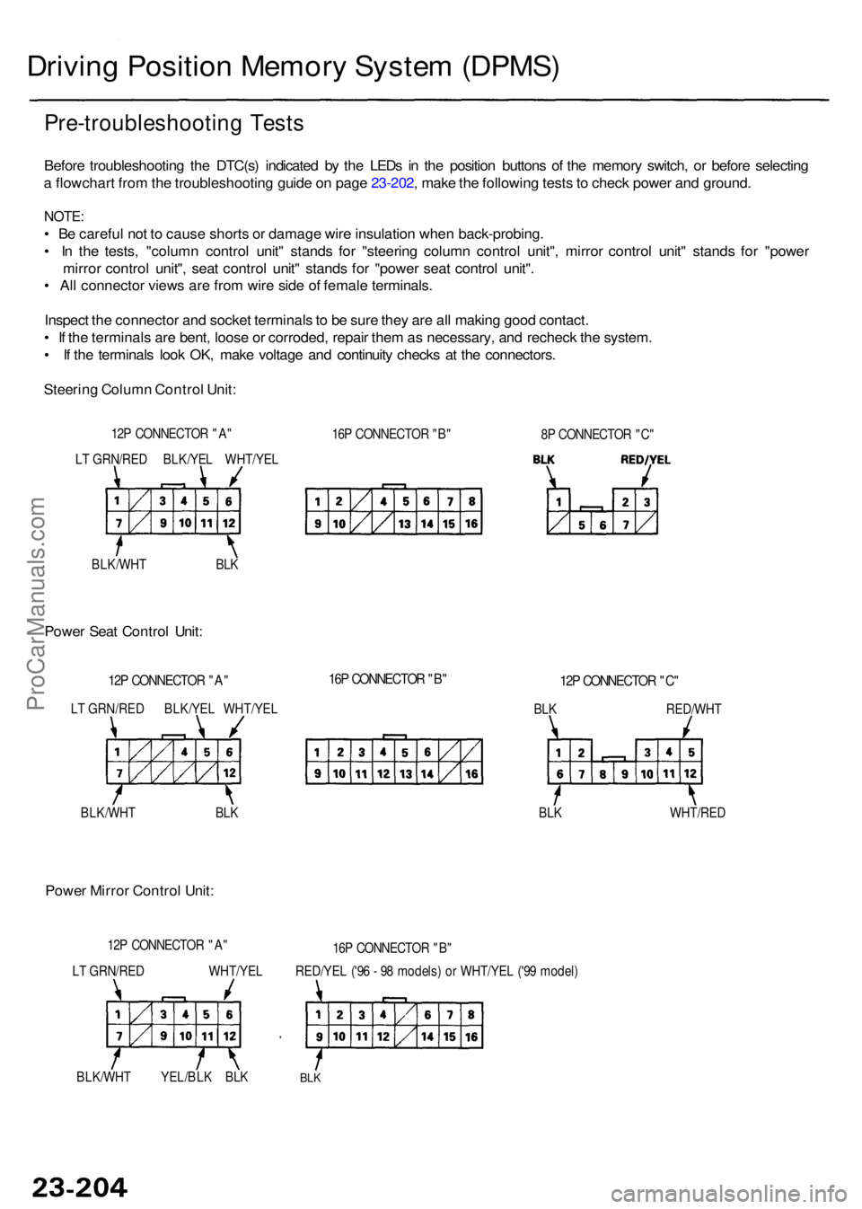
Pre-troubleshootin g Test s
Before troubleshootin g th e DTC(s ) indicate d b y th e LED s i n th e positio n button s o f th e memor y switch , o r befor e selectin g
a flowchar t fro m th e troubleshootin g guid e o n pag e 23-202 , mak e th e followin g test s to chec k powe r an d ground .
NOTE:
• B e carefu l no t t o caus e short s o r damag e wir e insulatio n whe n back-probing .
• I n th e tests , "colum n contro l unit " stand s fo r "steerin g colum n contro l unit" , mirro r contro l unit " stand s fo r "powe r
mirro r contro l unit" , sea t contro l unit " stand s fo r "powe r sea t contro l unit" .
• Al l connecto r view s ar e fro m wir e sid e o f femal e terminals .
Inspec t th e connecto r an d socke t terminal s to b e sur e the y ar e al l makin g goo d contact .
• I f th e terminal s ar e bent , loos e o r corroded , repai r the m as necessary , an d rechec k th e system .
• I f th e terminal s loo k OK , mak e voltag e an d continuit y check s a t th e connectors .
Steerin g Colum n Contro l Unit :
12P CONNECTO R "A "
16P CONNECTO R "B "
RED/YE L ('9 6 - 9 8 models ) o r WHT/YE L ('9 9 model )
L T GRN/RE D WHT/YE L
BLK/WH T YEL/BL K BL K
BLK
LT GRN/RE D BLK/YE L WHT/YE L
BLK/WH T BL K
BLK/WH
T BL K
L
T GRN/RE D BLK/YE L WHT/YE L
BLK WHT/RE D
BL
K RED/WH T
ProCarManuals.com
Page 1608 of 1954

Steering Colum n Contro l Unit :
Cavit y Wir e Tes t conditio nTest: Desire d resul tPossibl e caus e if resul t i s no t obtaine d
A5
A 6
C 3
A1 2
C1
A1
A7
BLK/YE L
WHT/YE L
RED/YEL
BLK
BL K
LT GRN/RE D
BLK/WHT
Ignition switc h O N (II )
Unde r al l condition s
Unde r al l condition s
Ignitio n switc h O N (II) ,
an d d o no t operat e DPM S
Ignition switc h O N (II) ,and d o no t operat e DPM SChec
k fo r voltag e t o ground :
Ther e shoul d b e batter y voltage .
Chec k fo r continuit y t o ground :
Ther e shoul d b e continuity .
Chec k fo r voltag e to ground :
Ther e shoul d b e n o voltage .
Chec k fo r voltag e t o ground :
Ther e shoul d b e approx . 5 V . •
Blow n No . 2 0 (2 0 A ) fus e in th e under -
das h fuse/rela y bo x
• A n ope n i n th e wire
• Blow n No . 5 6 (7. 5 A ) fus e in th e under -
hoo d fuse/rela y bo x
• A n ope n in th e wir e
• Blow n No . 5 4 (2 0 A ) fus e in th e under -
hoo d fuse/rela y bo x
• A n ope n i n th e wir e
• Poo r groun d (G401 , G40 2 o r G251 )
• A n ope n in th e wir e
• A n ope n o r shor t i n th e wir e
• A n ope n o r shor t i n th e wir e
Powe r Sea t Contro l Unit :
Cavit y Wir e Tes t conditio nTest: Desire d resul tPossibl e caus e if resul t i s no t obtaine d
A5
A6
C 5
C1 2
A12
C1
C 6
A1
A 7
BLK/YE L
WHT/YE L
RED/WH T
WHT/RED
BLK
BL K
BL K
LT GRN/RE D
BLK/WHT
Ignition switc h O N (II )
Unde r al l condition s
Unde r al l condition s
Unde r al l condition s
Under al l condition s
Ignition switc h O N (II) ,and d o no t operat e DPM S
Ignitio n switc h O N (II) ,and d o no t operat e DPM S
Check fo r voltag e to ground :There shoul d b e batter y voltage .
Check fo r continuit y t o ground :There shoul d b e continuity .
Chec k fo r voltag e t o ground :
Ther e shoul d b e n o voltage .
Chec k fo r voltag e t o ground :
Ther e shoul d b e approx . 5 V . •
Blow n No . 2 0 (2 0 A ) fus e in th e under -
das h fuse/rela y bo x
• A n ope n in th e wir e
• Blow n No . 5 6 (7. 5 A ) fus e in th e under -
hoo d fuse/rela y bo x
• A n ope n i n th e wire
• Blow n No . 1 1 (2 0 A ) fus e in th e under -dash fuse/rela y bo x
• A n ope n i n th e wir e
• Blow n No . 8 (2 0 A ) fus e in th e under -
das h fuse/rela y bo x
• A n ope n in th e wir e
• Poo r groun d (G401 , G40 2 o r G251 )
• A n ope n in th e wir e
• Poo r groun d (G651 , G681 )
• A n ope n in th e wir e
• A n ope n o r shor t i n th e wir e
• A n ope n o r shor t i n th e wir e
Powe r Mirro r Contro l Unit :
Cavit y Wir e Tes t conditio nTest: Desire d resul tPossibl e caus e if resul t i s no t obtaine d
B1
A 6
A1 1
B9
A1 2
A1
A7
RED/YE L(WHT/YEL )
WHT/YEL
YEL/BLK
BLK
BLK
LT GRN/RE D
BLK/WHT
Under al l condition s
Ignition switc h O N (II )
Unde r al l condition s
Ignition switc h O N (II) ,and d o no t operat e DPM S
Ignitio n switc h O N (II) ,
an d d o no t operat e DPM SChec
k fo r voltag e t o ground :
Ther e shoul d b e batter y voltage .
Chec k fo r continuit y t o ground :
Ther e shoul d b e continuity .
Chec k fo r voltag e t o ground :
Ther e shoul d b e n o voltage .
Chec k fo r voltag e t o ground :
Ther e shoul d b e approx . 5 V . •
Blow n No . 5 4 (2 0 A ) o r No . 5 6 (7. 5 A )
fus e in th e under-das h fuse/rela y bo x
• A n ope n in th e wir e
• Blow n No . 5 6 (7. 5 A ) fus e in th e under -
hoo d fuse/rela y bo x
• A n ope n in th e wire
• Blow n No . 1 9 (7. 5 A ) fus e in th e under -
das h fuse/rela y bo x
• A n ope n in th e wir e
• Poo r groun d (G401 , G40 2 o r G251 )
• A n ope n i n th e wir e
• A n ope n o r shor t i n th e wir e
• A n ope n o r shor t i n th e wir e
ProCarManuals.com
Page 1609 of 1954

Troubleshootin g
Flowchart No . 1
Ignitio n Ke y Switch :
Chec k fo r voltag e betwee n th e col -
um n contro l uni t 12 P connecto r A 4
te")
To pag e 23-207
Drivin g Positio n Memor y Syste m (DPMS )
Troubleshootin g
Flowchart No . 1
Ignitio n Ke y Switch :
Chec k fo r voltag e betwee n th e col -
um n contro l uni t 12 P connecto r A 4
termina l an d bod y ground . Ther e
shoul d b e 1 V or les s wit h th e igni -
tio n ke y inserte d an d 4 V or mor e
wit h th e ignitio n ke y removed .
• Ope n o r shor t i n th e BLU/WH T
wir e
- Fault y ignitio n ke y switc h
Ar
e voltage s a s specified ?
NO
YE S
Transmissio n Rang e Switch :Check fo r voltag e betwee n th e col -
um n contro l uni t 12 P connecto r
A1 0 termina l an d bod y ground .
Ther e shoul d b e 1 V or les s wit h
the shif t leve r i n o rmore wit h th e shif t leve r i n an yothe r positio n tha n
• Ope n o r shor t i n th e BLK/BL U
wir e
- Fault y transmissio n rang e switc h
NOAr e voltage s as specified ?
YES
Steerin g Colum n Aut o Switch :
Chec k fo r voltage betwee n th e
colum n contro l uni t 16 P connec -
to r B 4 termina l an d bod y ground .
Ther e shoul d b e 1 V or les s wit h
th e AUT O switc h O N an d 4 V or
mor e wit h th e AUT O switc h OFF .
Ar e voltage s a s specified ?
NO• Ope n o r shor t in th e L T BL U wir e
- Fault y AUT O switc h
YES
Vehicl e Spee d Senso r (VSS) :
1 . Rais e th e fron t o f th e vehicle ,
support i t wit h th e safet ystands , pu t i t i n neutral , an d
slowl y rotat e on e whee l wit h
othe r whee l blocked .
2 . Chec k fo r voltag e betwee n th e
colum n contro l uni t 12 P con -
necto r A1 1 termina l an d bod y
ground .
Doe s voltag e puls e fro m O to
abou t 5 V or more ? •
Ope n o r shor t i n th e BLU/WH T
wir e
- Fault y VS S (se e pag e 23-86 )
NO
YE S
Steerin g Colum n Positio n Sensor :
Chec k fo r voltag e betwee n th e
column contro l uni t 16 P connec -
to r B 2 an d B1 0 terminals .
NOTE : Al l colum n contro l uni t
connector s mus t b e connected .
I s ther e 5 V ?
NO • Ope n o r shor t in th e GR Y o r BR N
wire s
• Fault y steerin g positio n sensor s
YES
COLUM N CONTRO L UNI T16P CONNECTO R "B "
COLUM N CONTRO L UNI T12P CONNECTO R "A "
COLUM N CONTRO L UNI T
16 P CONNECTO R "B "
NOTE
: Al l connecto r view s ar e fro m wire
sid e o f femal e terminals .
COLUM N CONTRO L UNI T
12P CONNECTO R "A "
ProCarManuals.com
Page 1610 of 1954
 :Check fo r voltag e betwee n th e col -
um n contro l uni t 16 P connecto r B 9
an d B1 0 terminals . Ther e shoul d
b e 2. 5 V")
From pag e 23-206
Steerin g Colum n Positio n Senso r
(Extend-retract) :Check fo r voltag e betwee n th e col -
um n contro l uni t 16 P connecto r B 9
an d B1 0 terminals . Ther e shoul d
b e 2. 5 V or mor e wit h th e steerin g
colum n i n fully-extende d positio n
and 2. 5 V or les s wit h th e steerin gcolumn in fully-retracte d position .
NOTE : Al l colum n contro l uni t con -
nector s mus t b e connected . NOTE
: I f necessary , appl y powe r an d
groun d t o th e extend-retrac t moto r t o
mov e th e steerin g colum n t o th e fully -extende d an d fully-retracte d position s(see pag e 23-226 ).
Ar e voltage s a s specified ? •
Ope n o r shor t i n th e PN K o r BR Nwire s• Fault y extend-retrac t positio nsensor
NO
YE S
NOTE : I f necessary , appl y powe r an d
groun d to th e tilt moto r to mov e thesteerin g colum n t o th e fully-u p an d
fully-dow n position s (se e pag e 23-226 ).
Steerin
g Colum n Positio n Senso r
(Tilt) :
Chec k fo r voltag e betwee n th e col -
um n contro l uni t 16 P connecto r B 1
an d B1 0 terminals . Ther e shoul d
b e 2. 5 V or mor e wit h th e steerin g
colum n i n fully-u p positio n an d
2. 5 V or les s wit h th e steerin g
column in fully-dow n position .
NOTE : Al l colum n contro l uni t con -
nector s mus t b e connected .
Ar e voltage s a s specified ?
NO• Ope n o r shor t i n th e BL U o r BR Nwire s• Fault y til t positio n senso r
Extend-retrac t Moto r (Extend) :
Chec k fo r voltag e betwee n th e
extend-retrac t moto r 2 P connec -
to r No . 2 termina l an d bod y
ground . Ther e shoul d b e 1 2 V
wit h th e exten d switc h pushe d
an d n o voltag e wit h th e exten d
switch released .
Are voltage s a s specified ? •
Ope n o r shor t i n th e PNK/BL K
wir e
• Fault y exten d switc hNO
YE S
Extend-retrac t Moto r (Retract) :
Chec k fo r voltag e betwee n th e
extend-retrac t moto r 2 P connec -tor No . 1 termina l an d bod y
ground . Ther e shoul d b e 1 2 V
wit h th e retrac t switc h pushe d
an d n o voltag e wit h th e retrac t
switc h released .
Ar e voltage s a s specified ?
NO• Ope n o r shor t i n th e GRY/RE Dwire• Fault y retrac t switc h
T o pag e 23-208YE S(cont'd )
NOTE: Al l connecto r view s ar e fro m wir e
sid e o f femal e terminals .
COLUM N CONTRO L UNI T
16 P CONNECTO R "B "
EXTEND-RETRAC T MOTO R
2P CONNECTO R
ProCarManuals.com