ACURA RL KA9 1996 Service Repair Manual
Manufacturer: ACURA, Model Year: 1996, Model line: RL KA9, Model: ACURA RL KA9 1996Pages: 1954, PDF Size: 61.44 MB
Page 1591 of 1954
Switch Test/Replacemen t
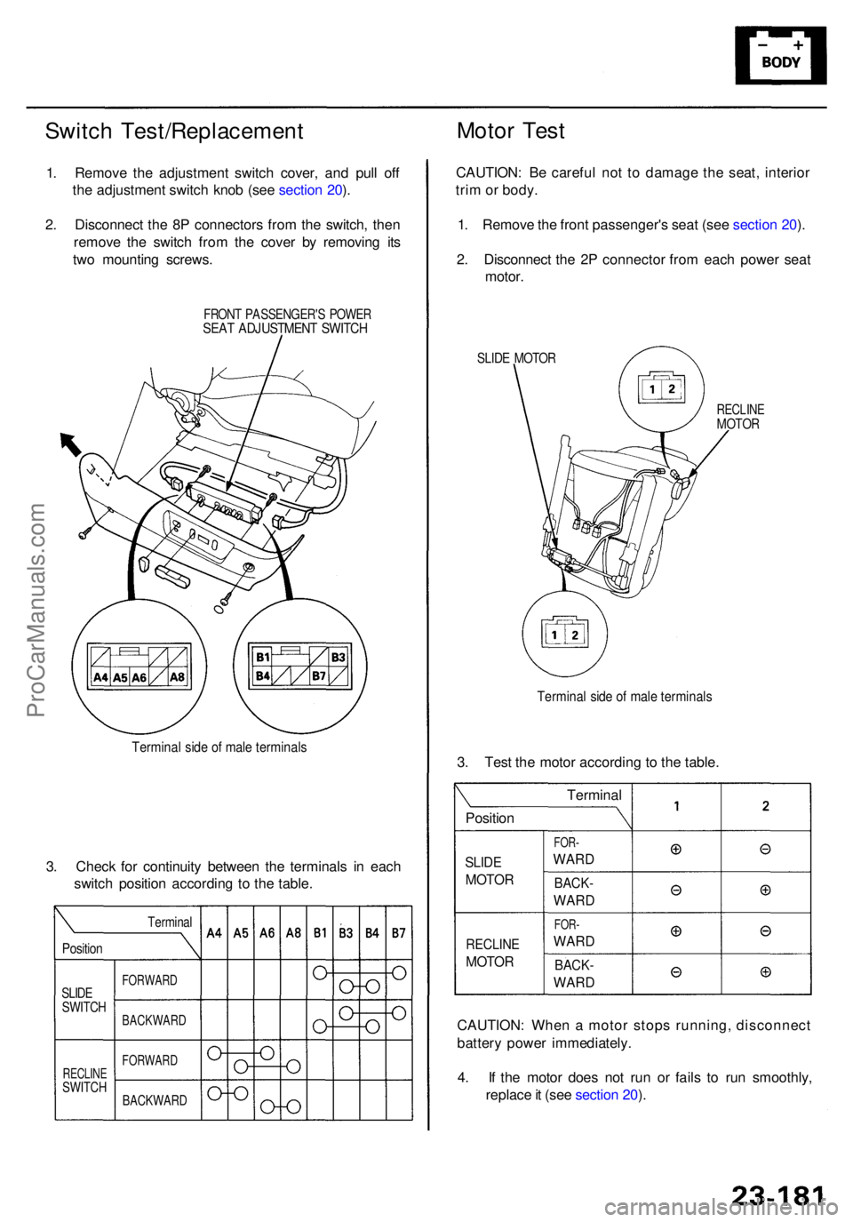
1. Remov e th e adjustmen t switc h cover , an d pul l of f
th e adjustmen t switc h kno b (se e sectio n 20 ).
2 . Disconnec t th e 8 P connector s fro m th e switch , the n
remov e th e switc h fro m th e cove r b y removin g it s
tw o mountin g screws .
FRONT PASSENGER' S POWE RSEAT ADJUSTMEN T SWITC H
Termina l sid e o f mal e terminal s
3. Chec k fo r continuit y betwee n th e terminal s i n eac h
switc h positio n accordin g t o th e table .
CAUTION: Whe n a moto r stop s running , disconnec t
batter y powe r immediately .
4 . I f th e moto r doe s no t ru n o r fail s t o ru n smoothly ,
replac e it (se e sectio n 20 ).
Moto r Tes t
CAUTION : B e carefu l no t t o damag e th e seat , interio r
tri m or body .
1 . Remov e th e fron t passenger' s sea t (se e sectio n 20 ).
2 . Disconnec t th e 2 P connecto r fro m eac h powe r sea t
motor .
SLIDE MOTO R
RECLIN EMOTOR
Termina l sid e o f mal e terminal s
3. Tes t th e moto r accordin g t o th e table .
SLIDE
MOTO R
FOR-
WAR D
Termina l
Positio n
BACK-
WARD
FOR-
WAR D
BACK -
WARD
RECLIN E
MOTORPosition
Termina l
FORWAR DSLIDESWITC HBACKWAR D
RECLINESWITCH
FORWAR D
BACKWAR D
ProCarManuals.com
Page 1592 of 1954
Immobilizer Syste m
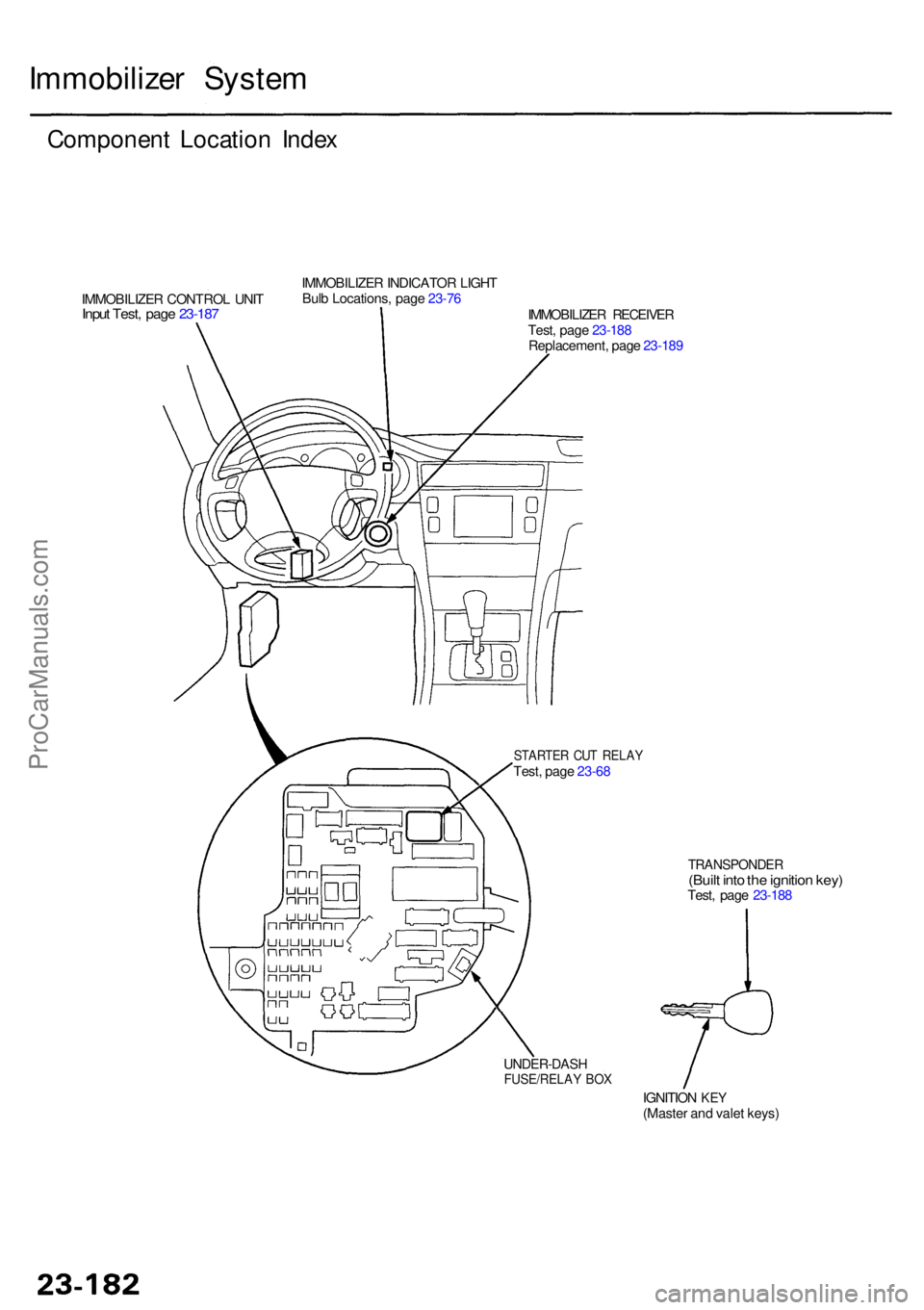
Componen t Locatio n Inde x
IMMOBILIZE R CONTRO L UNI TInput Test , pag e 23-18 7
IMMOBILIZE R INDICATO R LIGH T
Bul b Locations , pag e 23-76
IMMOBILIZER RECEIVE R
Test , pag e 23-18 8
Replacement , pag e 23-18 9
STARTE R CU T RELA YTest, pag e 23-6 8
TRANSPONDE R(Built int o th e ignitio n key )Test , pag e 23-18 8
IGNITIO N
KEY(Maste r an d vale t keys )
UNDER-DAS HFUSE/RELAY BO X
ProCarManuals.com
Page 1593 of 1954
Description
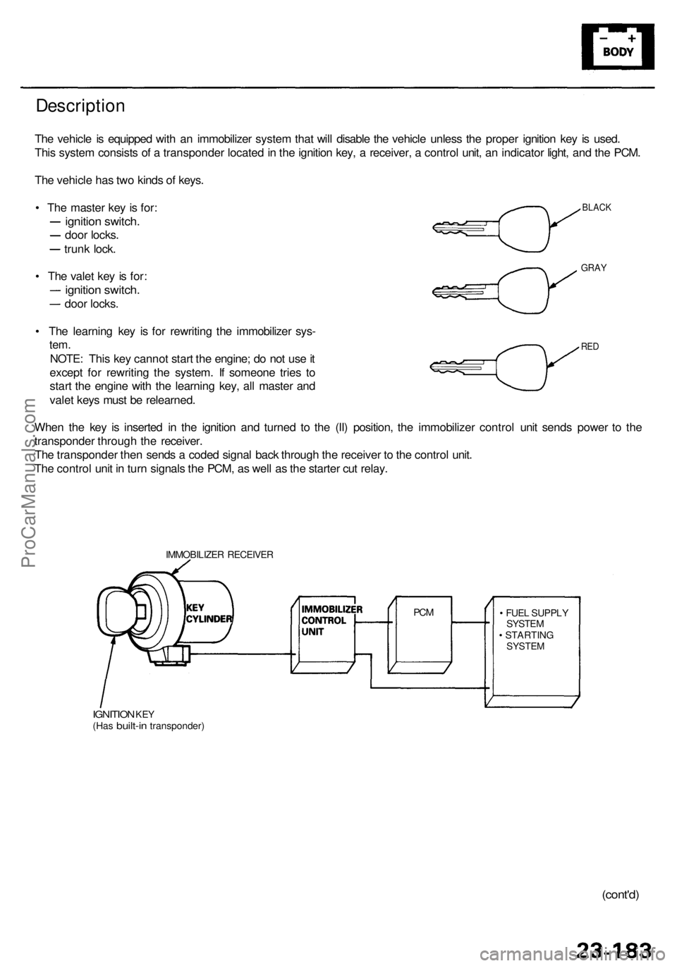
The vehicl e is equippe d wit h a n immobilize r syste m tha t wil l disabl e th e vehicl e unles s th e prope r ignitio n ke y i s used .
Thi s syste m consist s o f a transponde r locate d in th e ignitio n key , a receiver , a contro l unit , a n indicato r light , an d th e PCM .
Th e vehicl e ha s tw o kind s o f keys .
• Th e maste r ke y i s for :
ignitio n switch .
door locks .
trunk lock .
• Th e vale t ke y i s for :
ignitio n switch .
door locks .
• Th e learnin g ke y i s fo r rewritin g th e immobilize r sys -
tem.
NOTE : Thi s ke y canno t star t th e engine ; d o no t us e it
excep t fo r rewritin g th e system . I f someon e trie s t o
star t th e engin e wit h th e learnin g key , al l maste r an d
vale t key s mus t b e relearned .
Whe n th e ke y i s inserte d i n th e ignitio n an d turne d t o th e (II ) position , th e immobilize r contro l uni t send s powe r t o th e
transponde r throug h th e receiver .
Th e transponde r the n send s a code d signa l bac k throug h th e receive r t o th e contro l unit .
Th e contro l uni t i n tur n signal s th e PCM , a s wel l a s th e starte r cu t relay .
IMMOBILIZE R RECEIVE R
IGNITION KEY(Ha s built-i n transponder ) •
FUE L SUPPL Y
SYSTE M
• STARTIN G
SYSTEM
PCM
BLAC K
GRAY
RED
(cont'd )
ProCarManuals.com
Page 1594 of 1954
Immobilizer Syste m
Descriptio n (cont'd )
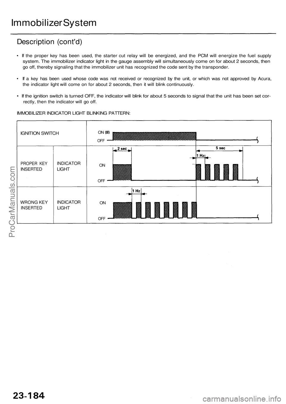
• I f th e prope r ke y ha s bee n used , th e starte r cu t rela y wil l b e energized , an d th e PC M wil l energiz e th e fue l suppl y
system . Th e immobilize r indicato r ligh t i n th e gaug e assembl y wil l simultaneousl y com e o n fo r abou t 2 seconds , the n
go off , thereb y signalin g tha t th e immobilize r uni t ha s recognize d th e cod e sen t b y th e transponder .
• I f a ke y ha s bee n use d whos e cod e wa s no t receive d o r recognize d b y th e unit , o r whic h wa s no t approve d b y Acura ,
th e indicato r ligh t wil l com e o n fo r abou t 2 seconds , the n it wil l blin k continuously .
• I f th e ignitio n switc h is turne d OFF , th e indicato r wil l blin k fo r abou t 5 second s to signa l tha t th e uni t ha s bee n se t cor -
rectly , the n th e indicato r wil l g o off .
IMMOBILIZE R INDICATO R LIGH T BLINKIN G PATTERN :
WRONG KE Y
INSERTE D
PROPER KE Y
INSERTE D
IGNITION SWITC H
INDICATO R
LIGHT
INDICATO R
LIGHT
ON
OF F
ON
OF F
ON
OF F
ProCarManuals.com
Page 1595 of 1954
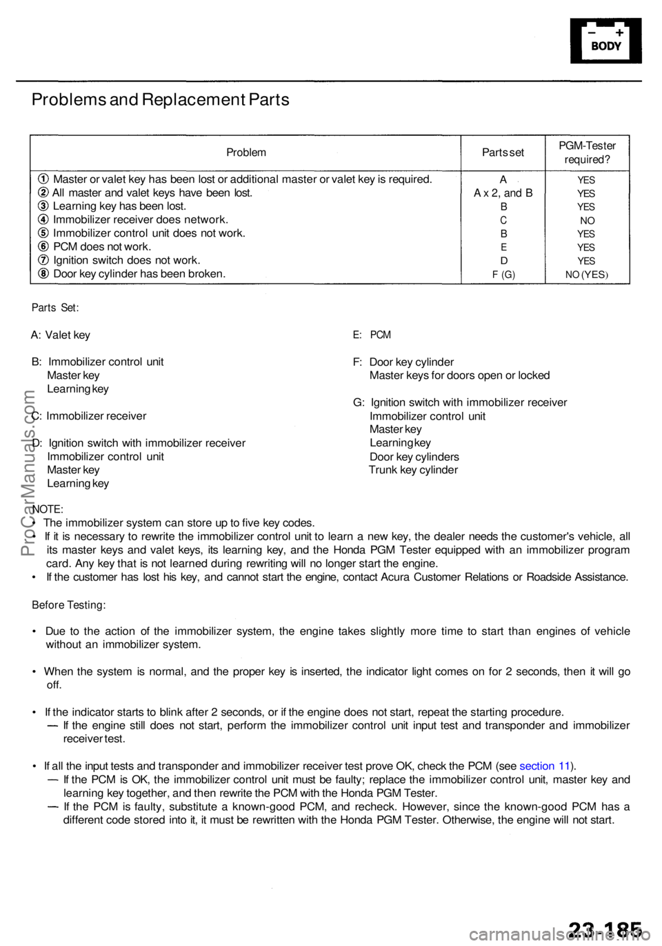
Problems an d Replacemen t Part s
Proble m
Master o r vale t ke y ha s bee n los t o r additiona l maste r o r vale t ke y is required .
Al l maste r an d vale t key s hav e bee n lost .
Learnin g ke y ha s bee n lost .
Immobilize r receive r doe s network .
Immobilize r contro l uni t doe s no t work .
PC M doe s no t work .
Ignitio n switc h doe s no t work .
Doo r ke y cylinde r ha s bee n broken . Part
s se t
PGM-Teste r
required?
YES
YES
YE S
NO
YE S
YE S
YES
NO (YES )
A
A x 2 , an d B
B
C
B
E
D
F (G )
Part s Set :
A: Vale t ke y
B : Immobilize r contro l uni t
Maste r ke y
Learnin g ke y
C : Immobilize r receive r
D : Ignitio n switc h wit h immobilize r receive r
Immobilize r contro l uni t
Maste r ke y
Learnin g ke yE: PC M
F: Doo r ke y cylinde r
Maste r key s fo r door s ope n o r locke d
G : Ignitio n switc h wit h immobilize r receive r
Immobilize r contro l uni t
Maste r ke y
Learnin g ke y
Doo r ke y cylinder s
Trun k ke y cylinde r
NOTE:
• Th e immobilize r syste m ca n stor e u p to fiv e ke y codes .
• I f i t i s necessar y t o rewrit e th e immobilize r contro l uni t t o lear n a ne w key , th e deale r need s th e customer' s vehicle , al l
it s maste r key s an d vale t keys , it s learnin g key , an d th e Hond a PG M Teste r equippe d wit h a n immobilize r progra m
card . An y ke y tha t i s no t learne d durin g rewritin g wil l n o longe r star t th e engine .
• I f th e custome r ha s los t hi s key , an d canno t star t th e engine , contac t Acur a Custome r Relation s o r Roadsid e Assistance .
Before Testing :
• Du e t o th e actio n o f th e immobilize r system , th e engin e take s slightl y mor e tim e t o star t tha n engine s o f vehicl e
withou t a n immobilize r system .
• Whe n th e syste m is normal , an d th e prope r ke y i s inserted , th e indicato r ligh t come s o n fo r 2 seconds , the n i t wil l g o
off .
• I f th e indicato r start s t o blin k afte r 2 seconds , o r i f th e engin e doe s no t start , repea t th e startin g procedure .
If th e engin e stil l doe s no t start , perfor m th e immobilize r contro l uni t inpu t tes t an d transponde r an d immobilize r
receive r test .
• I f al l th e inpu t test s an d transponde r an d immobilize r receive r tes t prov e OK , chec k th e PC M (se e sectio n 11 ).
I f th e PC M is OK , th e immobilize r contro l uni t mus t b e faulty ; replac e th e immobilize r contro l unit , maste r ke y an d
learnin g ke y together , an d the n rewrit e th e PC M wit h th e Hond a PG M Tester .
If th e PC M is faulty , substitut e a known-goo d PCM , an d recheck . However , sinc e th e known-goo d PC M ha s a
differen t cod e store d int o it , i t mus t b e rewritte n wit h th e Hond a PG M Tester . Otherwise , th e engin e wil l no t start .
ProCarManuals.com
Page 1596 of 1954
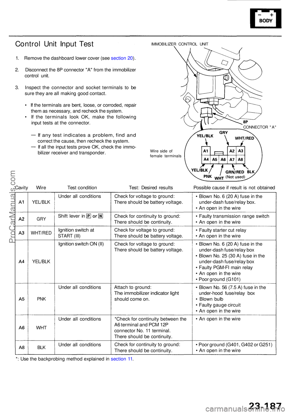
Control Uni t Inpu t Tes t
1. Remov e th e dashboar d lowe r cove r (se e sectio n 20 ).
2 . Disconnec t th e 8 P connecto r "A " fro m th e immobilize r
contro l unit .
3 . Inspec t th e connecto r an d socke t terminal s t o b e
sur e the y ar e al l makin g goo d contact .
• I f th e terminal s ar e bent , loose , o r corroded , repai r
the m as necessary , an d rechec k th e system .
• I f th e terminal s loo k OK , mak e th e followin g
inpu t test s a t th e connector .
If an y tes t indicate s a problem , fin d an d
correc t th e cause , the n rechec k th e system .
If al l th e inpu t test s prov e OK , chec k th e immo -
bilize r receive r an d transponder .
IMMOBILIZER CONTRO L UNI T
Wir e sid e o f
femal e terminal s
Cavity Wir e Tes t conditio n Test : Desire d result s Possibl e caus e if resul t i s no t obtaine d
YEL/BLK
GRY
WHT/RE D
YEL/BLK
PNK
WH T
BLK
Unde r al l condition s
Shif t leve r i n
Ignitio n switc h a t
STAR T (III )
Ignitio n switc h O N (II )
Unde r al l condition s
Unde r al l condition s
Unde r al l condition sChec
k fo r voltag e to ground :
Ther e shoul d b e batter y voltage .
Chec k fo r continuit y t o ground :
Ther e shoul d b e continuity .
Chec k fo r voltag e t o ground :
Ther e shoul d b e batter y voltage .
Chec k fo r voltag e to ground :
Ther e shoul d b e batter y voltage .
Attac h t o ground :
The immobilize r indicato r ligh t
shoul d com e on .
*Chec k fo r continuit y betwee n th e
A 6 termina l an d PC M 12 P
connecto r No . 1 1 terminal .
Ther e shoul d b e continuity .
Chec k fo r continuit y t o ground :
Ther e shoul d b e continuity . •
Poo r groun d (G401 , G40 2 o r G251 )
• A n ope n in th e wir e
•
A n ope n in th e wir e
•
Blow n No . 5 6 (7. 5 A ) fus e in th e
under-hoo d fuse/rela y bo x
• Blow n bul b
• Fault y gaug e circui t
• A n ope n in th e wir e
•
Blow n No . 6 (2 0 A ) fus e in th e
under-das h fuse/rela y bo x
• Blow n No . 2 5 (3 0 A ) fus e in th e
under-das h fuse/rela y bo x
• Fault y PGM-F I mai n rela y
• A n ope n in th e wir e
• Poo r groun d (G101 )
•
Fault y starte r cu t rela y
• A n ope n in th e wir e
•
Fault y transmissio n rang e switc h
• A n ope n i n th e wir e
•
Blow n No . 6 (2 0 A ) fus e in th e
under-das h fuse/rela y box .
• A n ope n in th e wir e
CONNECTO R "A "
*: Us e th e backprobin g metho d explaine d in sectio n 11 .
ProCarManuals.com
Page 1597 of 1954
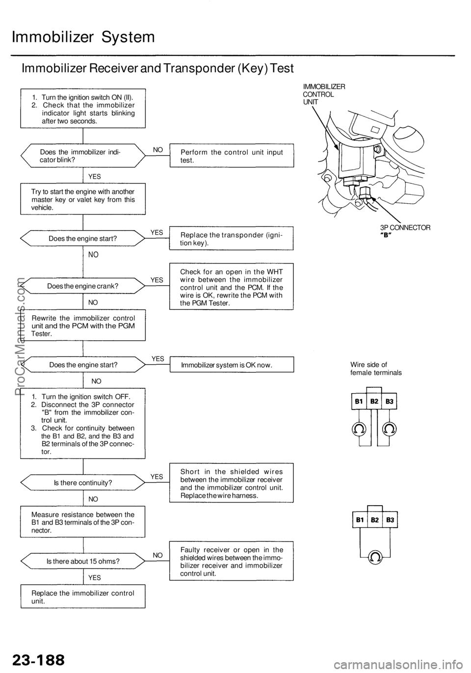
Immobilizer Syste m
Immobilize r Receive r an d Transponde r (Key ) Tes t
IMMOBILIZE RCONTROLUNIT
Doe s th e immobilize r indi -
cato r blink ? Perfor
m th e contro l uni t inpu t
test .
YES
Try to star t th e engin e wit h anothe r
maste r ke y o r vale t ke y fro m thi s
vehicle .
Doe s th e engin e start ? Replac
e th e transponde r (igni -
tio n key) .
3P CONNECTO R
NO
Doe s th e engin e crank ?
NO
Rewrit e th e immobilize r contro lunit an d th e PC M wit h th e PG MTester .
Check fo r a n ope n i n th e WH T
wir e betwee n th e immobilize r
contro l uni t an d th e PCM . I f th e
wir e is OK , rewrit e th e PC M wit h
th e PG M Tester .
Doe s th e engin e start ?
Immobilizer syste m is O K now . Wir
e sid e o f
femal e terminal s
I s ther e continuity ?
NO
Shor t i n th e shielde d wire s
betwee n th e immobilize r receive r
an d th e immobilize r contro l unit .
Replac e th e wir e harness .
Measur e resistanc e betwee n th e
B 1 an d B 3 terminal s o f th e 3 P con -
nector .
Is ther e abou t 1 5 ohms ?
YES
Fault y receive r o r ope n i n th e
shielde d wire s betwee n th e immo -
bilize r receive r an d immobilize r
contro l unit .
Replac e th e immobilize r contro l
unit .
1
. Tur n th e ignitio n switc h O N (II) .
2 . Chec k tha t th e immobilize r
indicato r ligh t start s blinkin g
afte r tw o seconds .
1 . Tur n th e ignitio n switc h OFF .
2 . Disconnec t th e 3 P connecto r
"B " fro m th e immobilize r con -
trol unit .3. Chec k fo r continuit y betwee nthe B 1 an d B2 , an d th e B 3 an dB2 terminal s o f th e 3 P connec -tor.
NO
YE S
YE S
NO
N
O
YE S
YES
ProCarManuals.com
Page 1598 of 1954
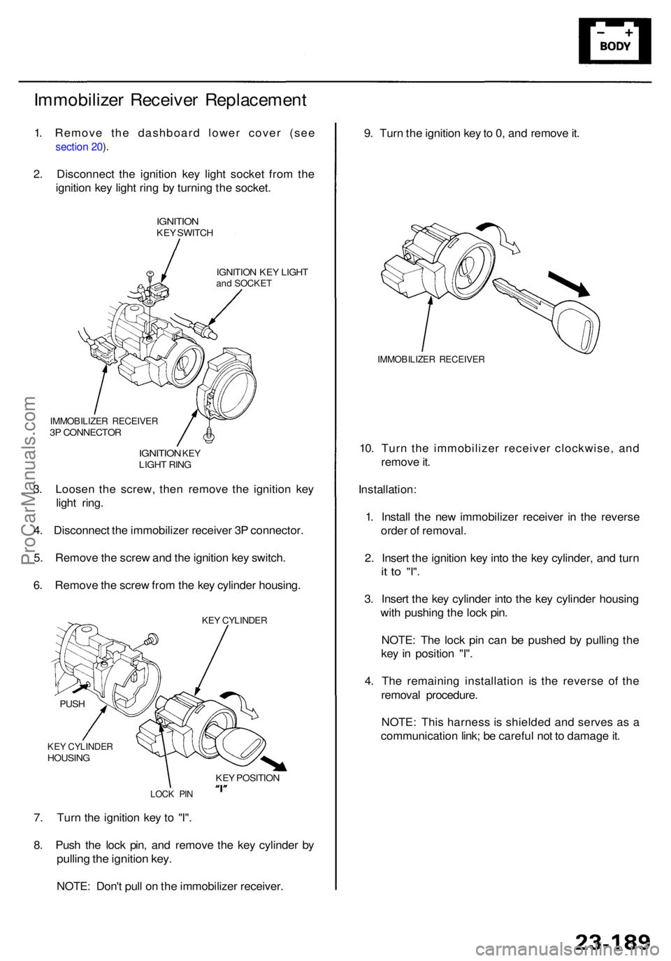
Immobilizer Receive r Replacemen t
1. Remove the dashboard lower cover (see
section 20 ).
2 . Disconnec t th e ignitio n ke y ligh t socke t fro m th e
ignitio n ke y ligh t rin g b y turnin g th e socket .
IGNITIO NKEY SWITC H
IGNITIO N KE Y LIGH T
and SOCKE T
9. Tur n th e ignitio n ke y to 0, an d remov e it .
IMMOBILIZE R RECEIVE R
10. Tur n th e immobilize r receive r clockwise , an d
remov e it .
Installation :
1. Instal l th e ne w immobilize r receive r i n th e revers e
orde r o f removal .
2 . Inser t th e ignitio n ke y int o th e ke y cylinder , an d tur n
it t o "I" .
3. Inser t th e ke y cylinde r int o th e ke y cylinde r housin g
wit h pushin g th e loc k pin .
NOTE : Th e loc k pi n ca n b e pushe d b y pullin g th e
ke y i n positio n "I" .
4 . Th e remainin g installatio n i s th e revers e o f th e
remova l procedure .
NOTE : Thi s harnes s i s shielde d an d serve s a s a
communicatio n link ; b e carefu l no t t o damag e it .
7 . Tur n th e ignitio n ke y t o "I" .
8 . Pus h th e loc k pin , an d remov e th e ke y cylinde r b y
pullin g th e ignitio n key .
NOTE : Don' t pul l o n th e immobilize r receiver .
3
. Loose n th e screw , the n remov e th e ignitio n ke y
ligh t ring .
4 . Disconnec t th e immobilize r receive r 3 P connector .
5 . Remov e th e scre w an d th e ignitio n ke y switch .
6 . Remov e th e scre w fro m th e ke y cylinde r housing .
IMMOBILIZE R RECEIVE R3P CONNECTO R
IGNITION KEYLIGH T RIN G
KEY CYLINDE RHOUSING
PUS
H
LOC K PI N
KEY POSITIO N
KEY CYLINDE R
ProCarManuals.com
Page 1599 of 1954
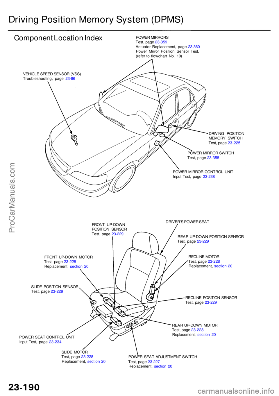
Driving Positio n Memor y Syste m (DPMS )
Componen t Locatio n Inde x
VEHICL E SPEE D SENSO R (VSS )
Troubleshooting , pag e 23-8 6 POWE
R MIRROR S
Test , pag e 23-35 9
Actuato r Replacement , pag e 23-36 0
Powe r Mirro r Positio n Senso r Test ,
(refe r t o flowchar t No . 10 )
DRIVING POSITIO N
MEMOR Y SWITC H
Test , pag e 23-22 5
POWE R MIRRO R SWITC H
Test , pag e 23-35 8
POWE R MIRRO R CONTRO L UNI T
Inpu t Test , pag e 23-23 8
FRON T UP-DOW N
POSITIO N SENSO R
Test , pag e 23-22 9 DRIVER'
S POWE R SEA T
REA R UP-DOW N POSITIO N SENSO R
Test , pag e 23-22 9
RECLIN E MOTO R
Test , pag e 23-22 8
Replacement , sectio n 2 0
RECLIN E POSITIO N SENSO R
Test , pag e 23-22 9
REA R UP-DOW N MOTO R
Test , pag e 23-22 8
Replacement , sectio n 2 0
POWE R SEA T ADJUSTMEN T SWITC H
Test , pag e 23-22 7
Replacement , sectio n 2 0
SLID
E MOTO R
Test , pag e 23-22 8
Replacement , sectio n 2 0
POWE
R SEA T CONTRO L UNI T
Inpu t Test , pag e 23-23 4
SLID
E POSITIO N SENSO R
Test , pag e 23-22 9
FRON
T UP-DOW N MOTO R
Test , pag e 23-22 8
Replacement , sectio n 2 0
ProCarManuals.com
Page 1600 of 1954
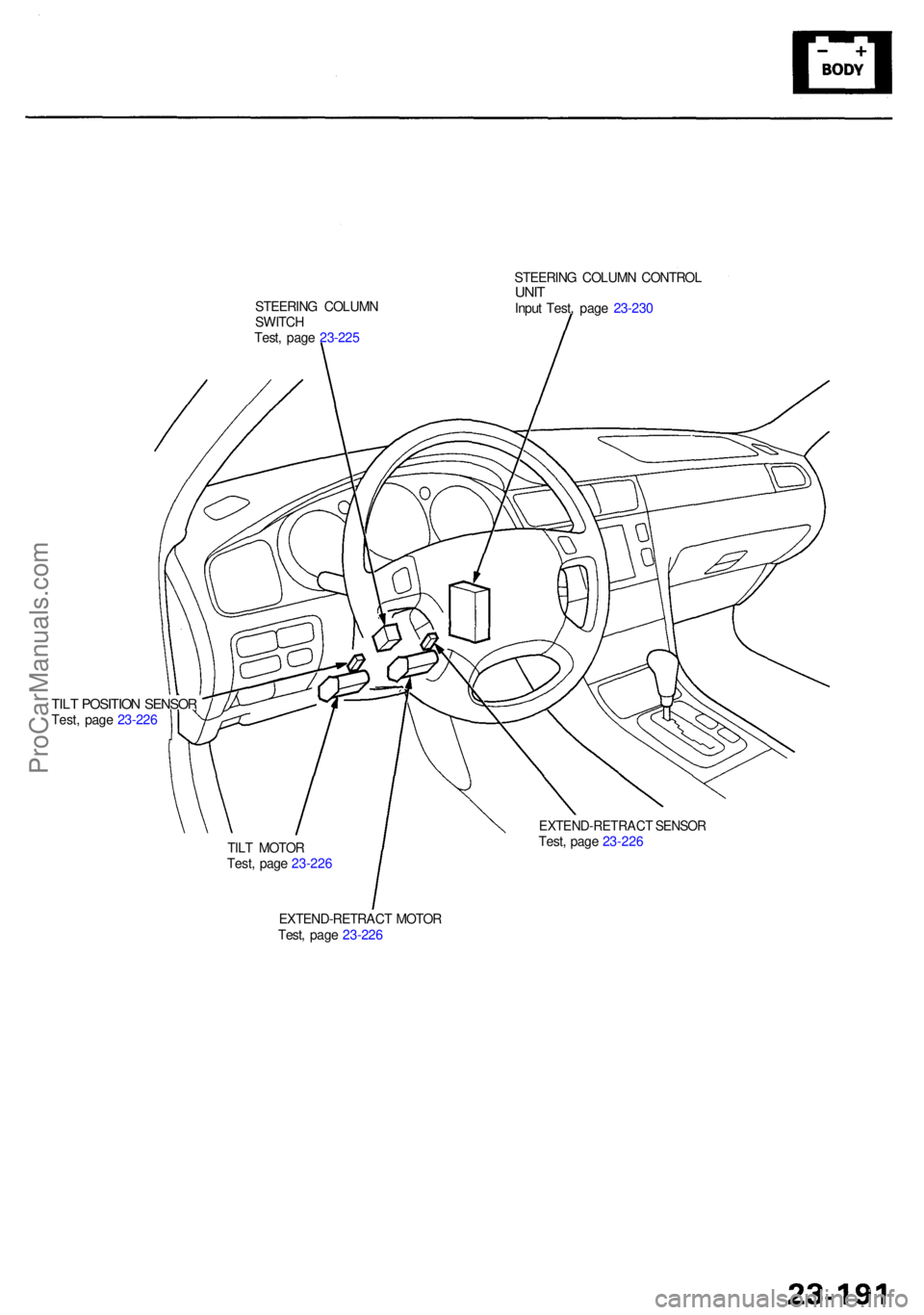
EXTEND-RETRACT MOTO R
Test , pag e 23-22 6
TIL
T MOTO R
Test , pag e 23-22 6
EXTEND-RETRAC T SENSO RTest, pag e 23-22 6
TILT POSITIO N SENSO RTest, pag e 23-22 6 STEERIN
G COLUM N
SWITC H
Test , pag e 23-22 5 STEERIN
G COLUM N CONTRO L
UNITInpu t Test , pag e 23-23 0
ProCarManuals.com