ACURA RL KA9 1996 Service Repair Manual
Manufacturer: ACURA, Model Year: 1996, Model line: RL KA9, Model: ACURA RL KA9 1996Pages: 1954, PDF Size: 61.44 MB
Page 1661 of 1954
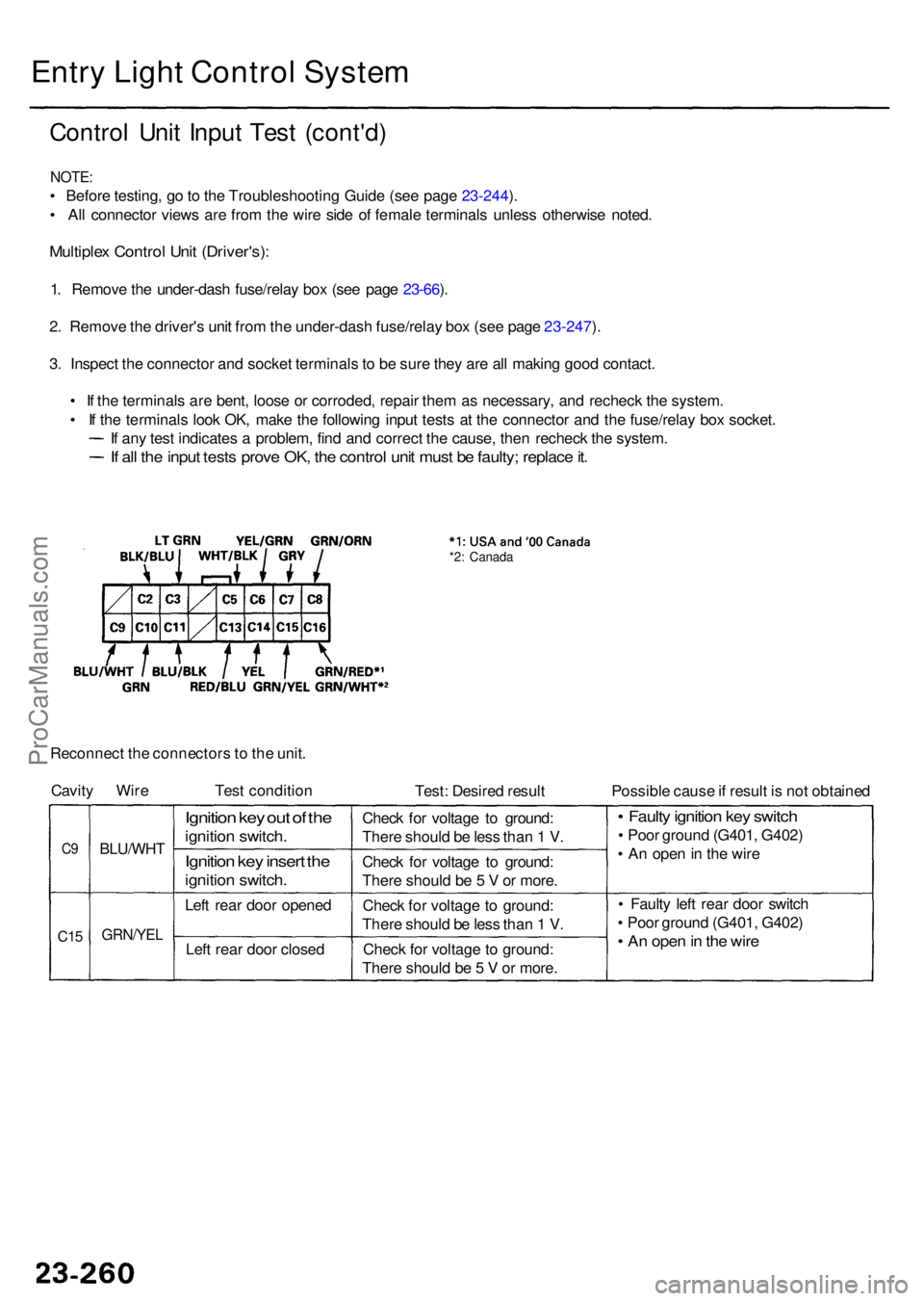
Entry Ligh t Contro l Syste m
Contro l Uni t Inpu t Tes t (cont'd )
NOTE:
• Befor e testing , g o to th e Troubleshootin g Guid e (se e pag e 23-244 ).
• Al l connecto r view s ar e fro m th e wir e sid e o f femal e terminal s unles s otherwis e noted .
Multiple x Contro l Uni t (Driver's) :
1. Remov e th e under-das h fuse/rela y bo x (se e pag e 23-66 ).
2 . Remov e th e driver' s uni t fro m th e under-das h fuse/rela y bo x (se e pag e 23-247 ).
3 . Inspec t th e connecto r an d socke t terminal s t o b e sur e the y ar e al l makin g goo d contact .
• I f th e terminal s ar e bent , loos e o r corroded , repai r the m a s necessary , an d rechec k th e system .
• I f th e terminal s loo k OK , mak e th e followin g inpu t test s a t th e connecto r an d th e fuse/rela y bo x socket .
I f an y tes t indicate s a problem , fin d an d correc t th e cause , the n rechec k th e system .
If al l th e inpu t test s prov e OK , th e contro l uni t mus t b e faulty ; replac e it .
*2 : Canad a
Reconnec t th e connector s to th e unit .
Cavit y Wir e Test conditio n
Test: Desire d resul t Possible caus e if resul t i s no t obtaine d
C9
C1 5
BLU/WH T
GRN/YEL
Ignition ke y ou t o f th e
ignitio n switch .
Ignition ke y inser t th e
ignitio n switch .
Left rea r doo r opene d
Lef t rea r doo r close d Chec
k fo r voltag e t o ground :
Ther e shoul d b e les s tha n 1 V .
Chec k fo r voltag e t o ground :
Ther e shoul d b e 5 V or more .
Chec k fo r voltag e t o ground :
Ther e shoul d b e les s tha n 1 V .
Chec k fo r voltag e to ground :
Ther e shoul d b e 5 V or more .
• Fault y ignitio n ke y switc h
• Poo r groun d (G401 , G402 )
• A n ope n in th e wir e
• Fault y lef t rea r doo r switc h
• Poo r groun d (G401 , G402 )
• A n ope n in th e wir e
ProCarManuals.com
Page 1662 of 1954
NOTE:
• Befor e testing , g o t o th e Troubleshootin g Guid e (se e pag e 23-244 ). B e sur e t o g o throug h self-diagnosi s functio n
modes 1 an d 2 (se e page s 23-24 8 an d 23-252 ).
• Al l connecto r view s ar e fro m th e wir e sid e o f femal e terminal s unles s otherwis e noted .
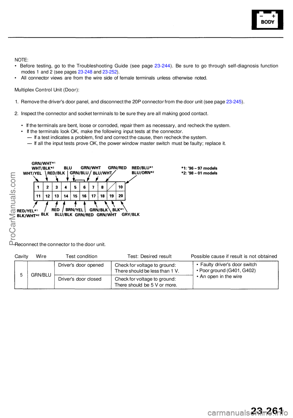
Multiple x Contro l Uni t (Door) :
1 . Remov e th e driver' s doo r panel , an d disconnec t th e 20 P connecto r fro m th e doo r uni t (se e pag e 23-245 ).
2 . Inspec t th e connecto r an d socke t terminal s to b e sur e the y ar e al l makin g goo d contact .
• I f th e terminal s ar e bent , loos e o r corroded , repai r the m a s necessary , an d rechec k th e system .
• I f th e terminal s loo k OK , mak e th e followin g inpu t test s a t th e connector .
I f a tes t indicate s a problem , fin d an d correc t th e cause , the n rechec k th e system .
I f al l th e inpu t test s prov e OK , th e powe r windo w maste r switc h mus t b e faulty ; replac e it .
Reconnec t th e connecto r t o th e doo r unit .
Cavit y Wir e Tes t conditio n Test : Desire d resul t Possibl e caus e if resul t i s no t obtaine d
Driver' s doo r opene d
Driver' s doo r close d
GRN/BL U5Check fo r voltag e to ground :
Ther e shoul d b e 5 V or more .
Chec
k fo r voltag e to ground :
Ther e shoul d b e les s tha n 1 V . •
Fault y driver' s doo r switc h
• Poo r groun d (G401 , G402 )
• A n ope n in th e wir e
ProCarManuals.com
Page 1663 of 1954
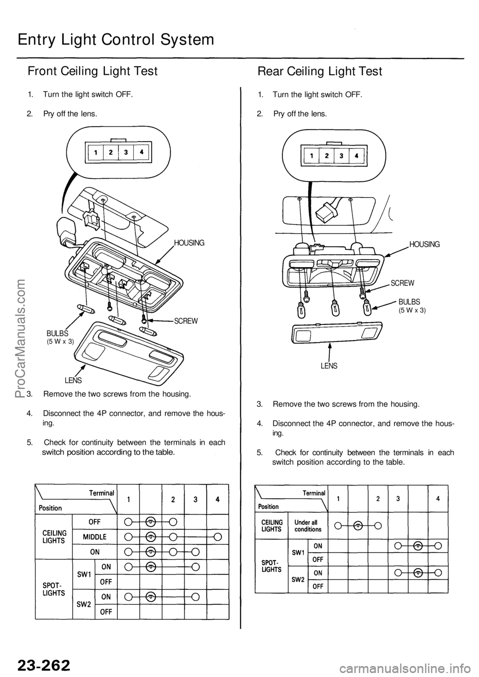
Entry Ligh t Contro l Syste m
Front Ceilin g Ligh t Tes t
1. Tur n th e ligh t switc h OFF .
2 . Pr y of f th e lens .
Rear Ceilin g Ligh t Tes t
1. Tur n th e ligh t switc h OFF .
2 . Pr y of f th e lens .
BULB S(5 W x 3)
SCRE W
HOUSIN G
LEN S
3. Remov e th e tw o screw s fro m th e housing .
4 . Disconnec t th e 4 P connector , an d remov e th e hous -
ing.
5. Chec k fo r continuit y betwee n th e terminal s i n eac h
switc h positio n accordin g to th e table .
3. Remov e th e tw o screw s fro m th e housing .
4 . Disconnec t th e 4 P connector , an d remov e th e hous -
ing.
5. Chec k fo r continuit y betwee n th e terminal s i n eac h
switc h positio n accordin g t o th e table .
HOUSIN G
SCREW
BULBS(5 W x 3)
LEN S
ProCarManuals.com
Page 1664 of 1954
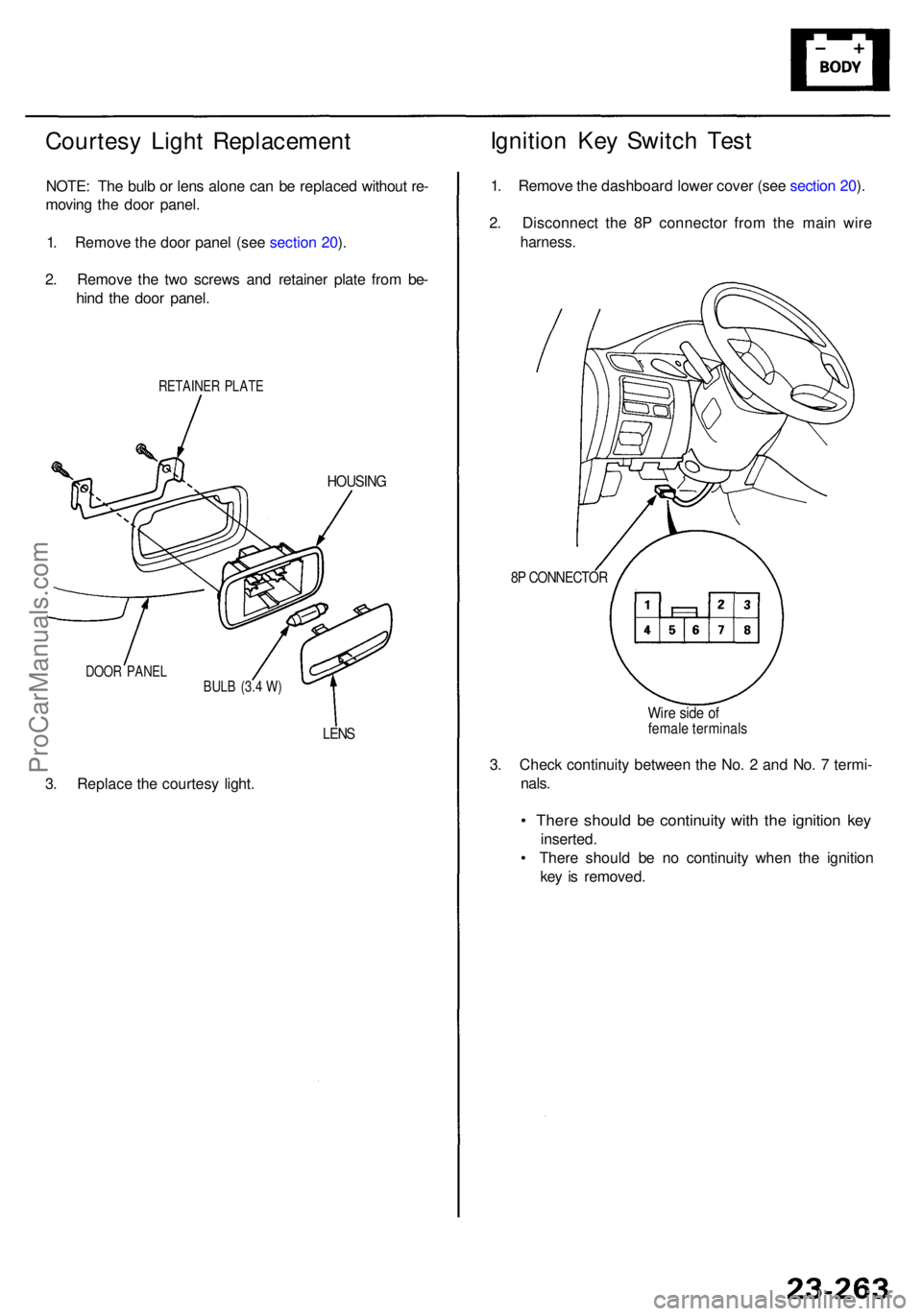
Courtesy Ligh t Replacemen t
NOTE: Th e bul b o r len s alon e ca n b e replace d withou t re -
movin g th e doo r panel .
1 . Remov e th e doo r pane l (se e sectio n 20 ).
2 . Remov e th e tw o screw s an d retaine r plat e fro m be -
hin d th e doo r panel .
RETAINE R PLAT E
HOUSIN G
DOOR PANE L
BULB (3. 4 W )
3. Replac e th e courtes y light .
LENS
3. Chec k continuit y betwee n th e No . 2 an d No . 7 termi -
nals .
• Ther e shoul d b e continuit y wit h th e ignitio n ke y
inserted .
• Ther e shoul d b e n o continuit y whe n th e ignitio n
ke y i s removed .
Ignition Ke y Switc h Tes t
1. Remov e th e dashboar d lowe r cove r (se e sectio n 20 ).
2 . Disconnec t th e 8 P connecto r fro m th e mai n wir e
harness .
8P CONNECTO R
Wire sid e o ffemal e terminal s
ProCarManuals.com
Page 1665 of 1954
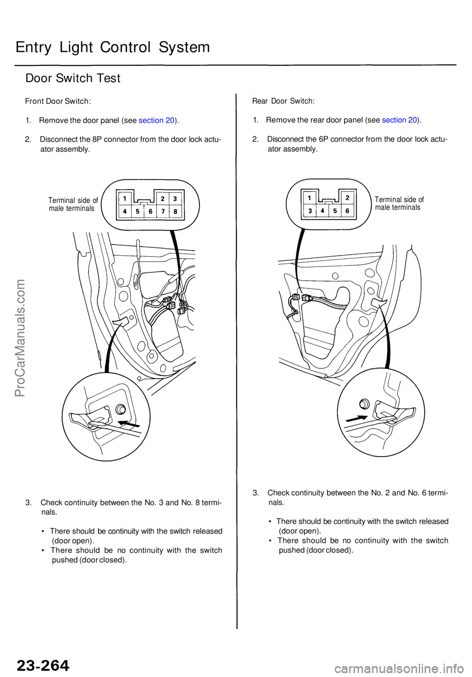
3. Chec k continuit y betwee n th e No . 3 an d No . 8 termi -
nals.
• Ther e shoul d b e continuit y wit h th e switc h release d
(doo r open) .
• Ther e shoul d b e n o continuit y wit h th e switc h
pushe d (doo r closed) .
Entry Ligh t Contro l Syste m
Door Switc h Tes t
Fron t Doo r Switch :
1 . Remov e th e doo r pane l (se e sectio n 20 ).
2 . Disconnec t th e 8 P connecto r fro m th e doo r loc k actu -
ato r assembly .
Terminal sid e o f
mal e terminal s
Rear Doo r Switch :
1. Remov e th e rea r doo r pane l (se e sectio n 20 ).
2 . Disconnec t th e 6 P connecto r fro m th e doo r loc k actu -
ato r assembly .
Terminal sid e o f
mal e terminal s
3. Chec k continuit y betwee n th e No . 2 an d No . 6 termi -
nals.
• Ther e shoul d b e continuit y wit h th e switc h release d
(doo r open) .
• Ther e shoul d b e n o continuit y wit h th e switc h
pushe d (doo r closed) .
ProCarManuals.com
Page 1666 of 1954
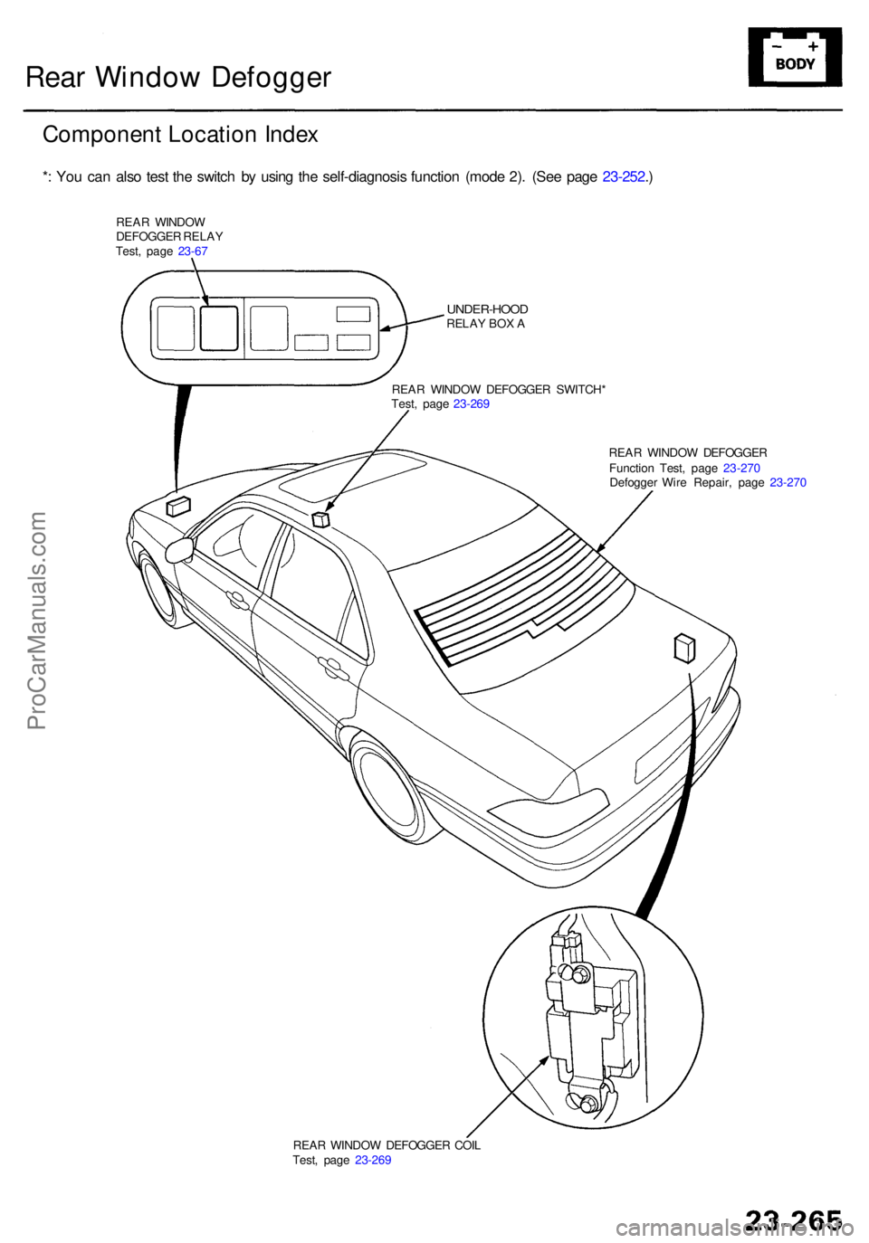
REAR WINDO W DEFOGGE R COI L
Test , pag e 23-26 9
Rear Windo w Defogge r
Componen t Locatio n Inde x
*: Yo u ca n als o tes t th e switc h b y usin g th e self-diagnosi s functio n (mod e 2) . (Se e pag e 23-252 .)
REA R WINDO W
DEFOGGE R RELA Y
Test , pag e 23-6 7
UNDER-HOO DRELAY BO X A
REA R WINDO W DEFOGGE R SWITCH *
Test , pag e 23-26 9
REAR WINDO W DEFOGGE R
Functio n Test , pag e 23-27 0
Defogge r Wir e Repair , pag e 23-27 0
ProCarManuals.com
Page 1667 of 1954
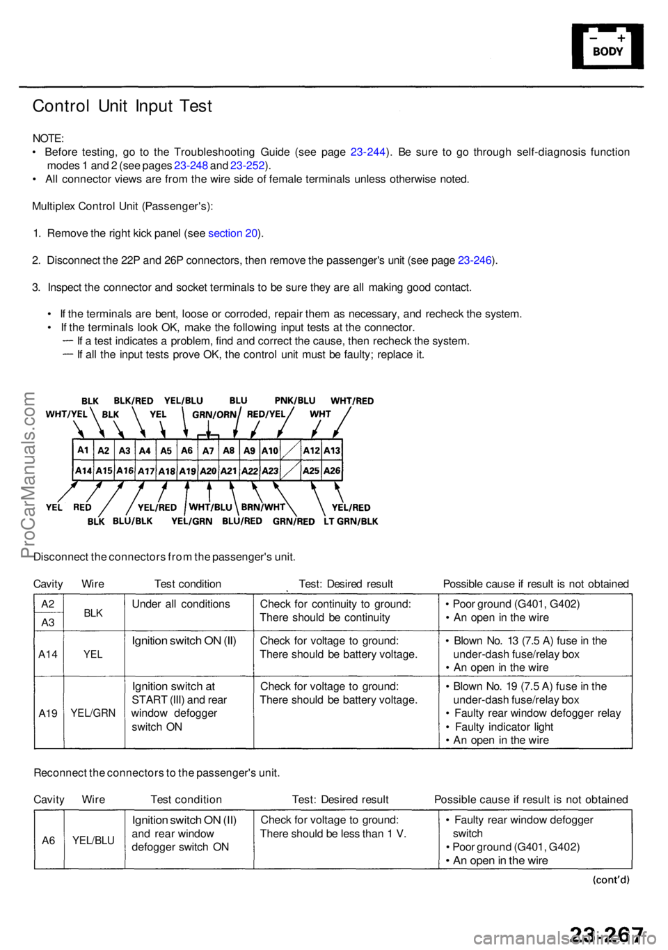
Control Uni t Inpu t Tes t
NOTE :
• Befor e testing , g o t o th e Troubleshootin g Guid e (se e pag e 23-244 ). B e sur e t o g o throug h self-diagnosi s functio n
mode s 1 an d 2 (se e page s 23-24 8 an d 23-252 ).
• Al l connecto r view s ar e fro m th e wir e sid e o f femal e terminal s unles s otherwis e noted .
Multiple x Contro l Uni t (Passenger's) :
1 . Remov e th e righ t kic k pane l (se e sectio n 20 ).
2 . Disconnec t th e 22 P an d 26 P connectors , the n remov e th e passenger' s uni t (se e pag e 23-246 ).
3 . Inspec t th e connecto r an d socke t terminal s t o b e sur e the y ar e al l makin g goo d contact .
• I f th e terminal s ar e bent , loos e o r corroded , repai r the m a s necessary , an d rechec k th e system .
• I f th e terminal s loo k OK , mak e th e followin g inpu t test s a t th e connector .
I f a tes t indicate s a problem , fin d an d correc t th e cause , the n rechec k th e system .
I f al l th e inpu t test s prov e OK , th e contro l uni t mus t b e faulty ; replac e it .
Disconnec t th e connector s fro m th e passenger' s unit .
Cavit y Wir e Tes t conditio n Test : Desire d resul t Possibl e caus e if resul t i s no t obtaine d
Ignition switc h O N (II )
Ignitio n switc h a t
STAR T (III ) an d rea r
windo w defogge r
switc h O N
YEL/GR N
YEL
BLKUnde r al l condition sCheck fo r continuit y t o ground :
Ther e shoul d b e continuit y
Chec k fo r voltag e t o ground :
Ther e shoul d b e batter y voltage .
Chec k fo r voltag e t o ground :
Ther e shoul d b e batter y voltage .
A19
A1 4
A3
A 2
• Blow n No . 1 9 (7. 5 A ) fus e in th e
under-das h fuse/rela y bo x
• Fault y rea r windo w defogge r rela y
• Fault y indicator light
• A n ope n i n th e wir e
•
Blow n No . 1 3 (7. 5 A ) fus e in th e
under-das h fuse/rela y bo x
• A n ope n in th e wir e
•
Poo r groun d (G401 , G402 )
• A n ope n in th e wir e
Reconnec t th e connector s to th e passenger' s unit .
Cavit y Wir e Tes t conditio n Test : Desire d resul t Possibl e caus e if resul t i s no t obtaine d
• Fault y rea r windo w defogge r
switc h
• Poo r groun d (G401 , G402 )
• A n ope n in th e wir e
Chec k fo r voltag e t o ground :
Ther e shoul d b e les s tha n 1 V .Ignitio n switc h O N (II )
an d rea r windo w
defogge r switc h O NYEL/BL UA6
ProCarManuals.com
Page 1668 of 1954
Rear Windo w Defogge r
Control Uni t Inpu t Tes t (cont'd )
NOTE: Befor e testing , g o t o th e Troubleshootin g Guid e (se e pag e 23-244 ). B e sur e t o g o throug h self-diagnosi s functio n
mode s 1 an d 2 (se e page s 23-24 8 an d 23-252 ).
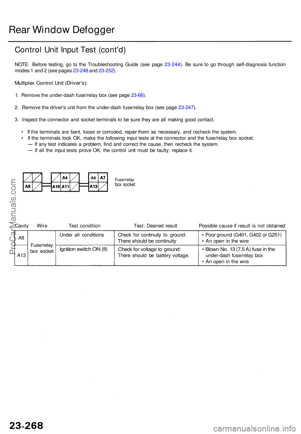
Multiple x Contro l Uni t (Driver's) :
1. Remov e th e under-das h fuse/rela y bo x (se e pag e 23-66 ).
2 . Remov e th e driver' s uni t fro m th e under-das h fuse/rela y bo x (se e pag e 23-247 ).
3 . Inspec t th e connecto r an d socke t terminal s t o b e sur e the y ar e al l makin g goo d contact .
• I f th e terminal s ar e bent , loos e o r corroded , repai r the m a s necessary , an d rechec k th e system .
• I f th e terminal s loo k OK , mak e th e followin g inpu t test s a t th e connecto r an d th e fuse/rela y bo x socket .
I f an y tes t indicate s a problem , fin d an d correc t th e cause , the n rechec k th e system .
I f al l th e inpu t test s prov e OK , th e contro l uni t mus t b e faulty ; replac e it .
Fuse/rela ybox socke t
Cavity Wir e Tes t conditio n Test : Desire d resul t Possibl e caus e if resul t i s no t obtaine d
Fuse/rela y
box socke t
A8
A1 3
Ignitio n switc h O N (II )
Unde r al l condition sCheck fo r continuit y t o ground :
There shoul d b e continuit y
Check fo r voltag e to ground :
There shoul d b e batter y voltage .
• Blow n No . 1 3 (7. 5 A ) fus e in th e
under-das h fuse/rela y bo x
• A n ope n in th e wir e
•
Poo r groun d (G401 , G40 2 o r G251 )
• A n ope n in th e wir e
ProCarManuals.com
Page 1669 of 1954
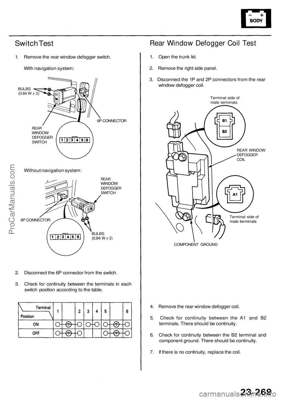
Switch Tes t
1. Remov e th e rea r windo w defogge r switch .
Wit h navigatio n system :
REARWINDO WDEFOGGE RSWITCH 6
P CONNECTO R
BULBS(0.84 W x 2)
Withou t navigatio n system :
REARWINDO WDEFOGGE RSWITCH
6 P CONNECTO R
BULBS(0.84 W x 2)
2. Disconnec t th e 6 P connecto r fro m th e switch .
3 . Chec k fo r continuit y betwee n th e terminal s i n eac h
switc h positio n accordin g to th e table .
Rear Windo w Defogge r Coi l Tes t
1. Ope n th e trunk lid.
2 . Remov e th e righ t sid e panel .
3 . Disconnec t th e 1 P an d 2 P connector s fro m th e rea r
windo w defogge r coil .
Termina l sid e o f
mal e terminal s
REAR WINDO WDEFOGGE RCOIL
Termina l sid e o fmal e terminal s
COMPONEN T GROUN D
4. Remov e th e rea r windo w defogge r coil .
5 . Chec k fo r continuit y betwee n th e A 1 an d B 2
terminals . Ther e shoul d b e continuity .
6 . Chec k fo r continuit y betwee n th e B 2 termina l an d
componen t ground . Ther e shoul d b e continuity .
7 . I f ther e is n o continuity , replac e th e coil .
ProCarManuals.com
Page 1670 of 1954
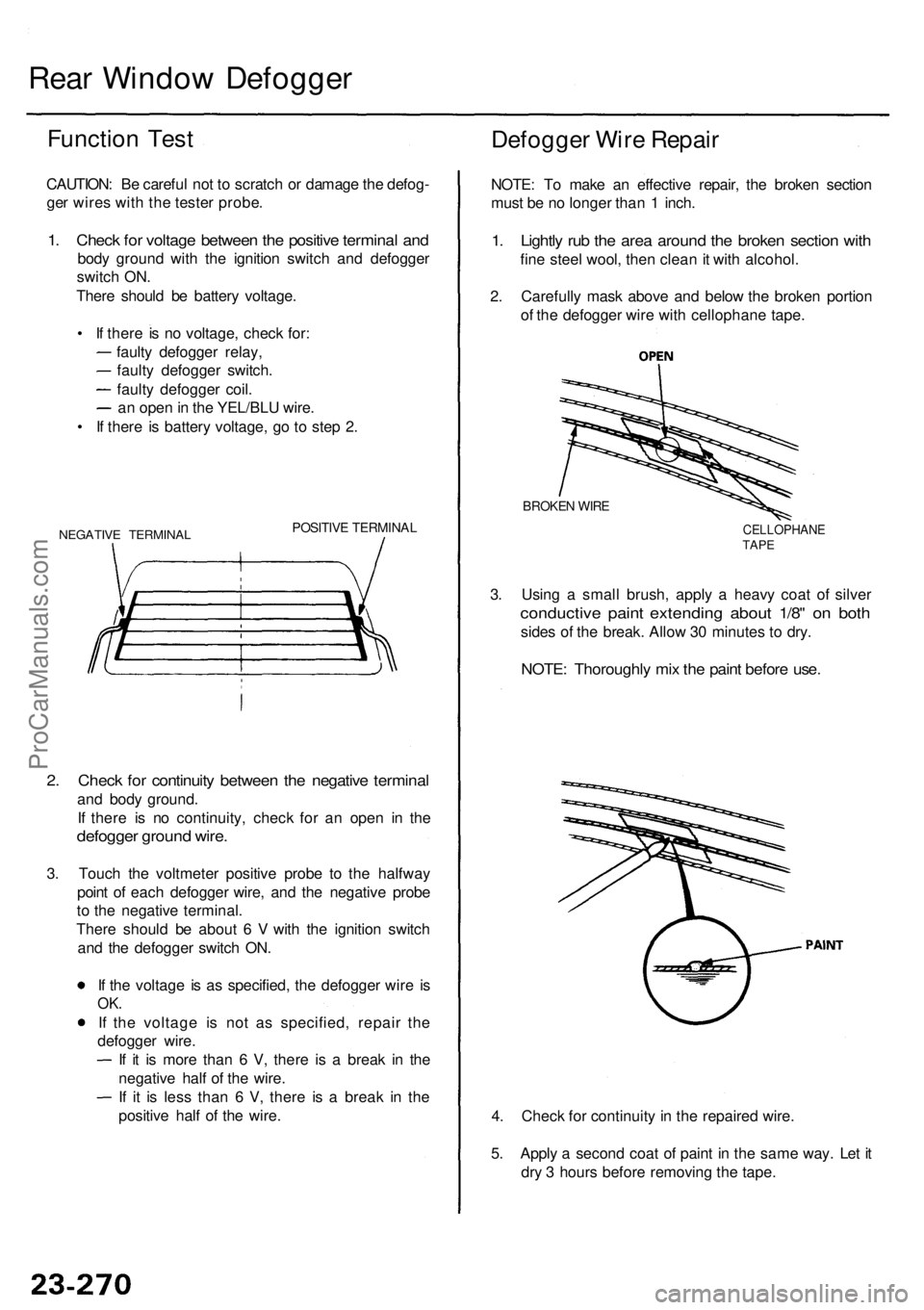
Rear Windo w Defogge r
Function Tes t
CAUTION : B e carefu l no t t o scratc h o r damag e th e defog -
ge r wire s wit h th e teste r probe .
1. Chec k fo r voltag e betwee n th e positiv e termina l an d
bod y groun d wit h th e ignitio n switc h an d defogge r
switc h ON .
Ther e shoul d b e batter y voltage .
• I f ther e is n o voltage , chec k for :
fault y defogge r relay ,
fault y defogge r switch .
fault y defogge r coil .
a n ope n in th e YEL/BL U wire .
• I f ther e i s batter y voltage , g o t o ste p 2 .
NEGATIV E TERMINA LPOSITIVE TERMINA L
2. Chec k fo r continuit y betwee n th e negativ e termina l
and bod y ground .
I f ther e i s n o continuity , chec k fo r a n ope n i n th e
defogge r groun d wire .
3. Touc h th e voltmete r positiv e prob e t o th e halfwa y
poin t o f eac h defogge r wire , an d th e negativ e prob e
t o th e negativ e terminal .
Ther e shoul d b e abou t 6 V with th e ignitio n switc h
an d th e defogge r switc h ON .
I f th e voltag e i s a s specified , th e defogge r wir e i s
OK .
If th e voltag e i s no t a s specified , repai r th e
defogge r wire .
I f i t i s mor e tha n 6 V , ther e i s a brea k i n th e
negativ e hal f o f th e wire .
I f i t i s les s tha n 6 V , ther e i s a brea k i n th e
positiv e hal f o f th e wire .
Defogge r Wir e Repai r
NOTE: T o mak e a n effectiv e repair , th e broke n sectio n
mus t b e n o longe r tha n 1 inch .
1. Lightl y ru b th e are a aroun d th e broke n sectio n wit h
fine stee l wool , the n clea n it wit h alcohol .
2 . Carefull y mas k abov e an d belo w th e broke n portio n
o f th e defogge r wir e wit h cellophan e tape .
3 . Usin g a smal l brush , appl y a heav y coa t o f silve r
conductiv e pain t extendin g abou t 1/8 " o n bot h
sides o f th e break . Allo w 3 0 minute s t o dry .
BROKE N WIR E
CELLOPHAN ETAPE
NOTE : Thoroughl y mi x th e pain t befor e use .
4. Chec k fo r continuit y in th e repaire d wire .
5 . Appl y a secon d coa t o f pain t i n th e sam e way . Le t i t
dr y 3 hour s befor e removin g th e tape .
ProCarManuals.com