ACURA RL KA9 1996 Service Repair Manual
Manufacturer: ACURA, Model Year: 1996, Model line: RL KA9, Model: ACURA RL KA9 1996Pages: 1954, PDF Size: 61.44 MB
Page 1611 of 1954
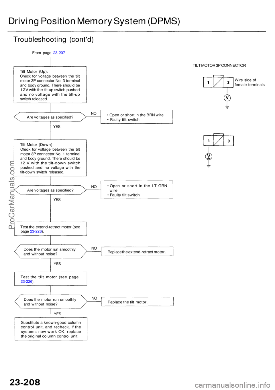
Driving Positio n Memor y Syste m (DPMS )
Troubleshootin g (cont'd )
From page 23-207
Til t Moto r (Up) :
Chec k
for voltag e betwee n the tiltmoto r 3 P connecto r No . 3 termina l
an d bod y ground . Ther e shoul d b e
12 V wit h th e tilt-u p switc h pushe dand n o voltag e wit h th e tilt-u pswitch released .
• Ope n o r shor t i n th e BR N wir e
• Fault y tilt switc h
Ar
e voltage s a s specified ?
NO
YE S
Tilt Moto r (Down) :Check for voltag e betwee n the tiltmoto r 3 P connecto r No . 1 termina l
an d bod y ground . Ther e shoul d b e
12 V wit h th e tilt-dow n switc hpushed an d n o voltag e wit h th e
tilt-dow n switc h released .
• Ope n o r shor t i n th e L T GR N
wir e
• Fault y til t switc h
NOAr e voltage s a s specified ?
YES
Tes t th e extend-retrac t moto r (se epag e 23-226 ).
Doe s th e moto r ru n smoothl yand withou t noise ? Replac
e th e extend-retrac t motor .
NO
YE S
Test the tilt motor (see page23-226 ).
Doe s th e moto r ru n smoothl y
an d withou t noise ?NOReplac e th e til t motor .
YES
Substitut e a known-goo d colum n
contro l unit , an d recheck . I f th e
system s no w wor k OK , replac e
the origina l colum n contro l unit .
TILT MOTO R 3P CONNECTO R
Wir e sid e o f
femal e terminal s
ProCarManuals.com
Page 1612 of 1954
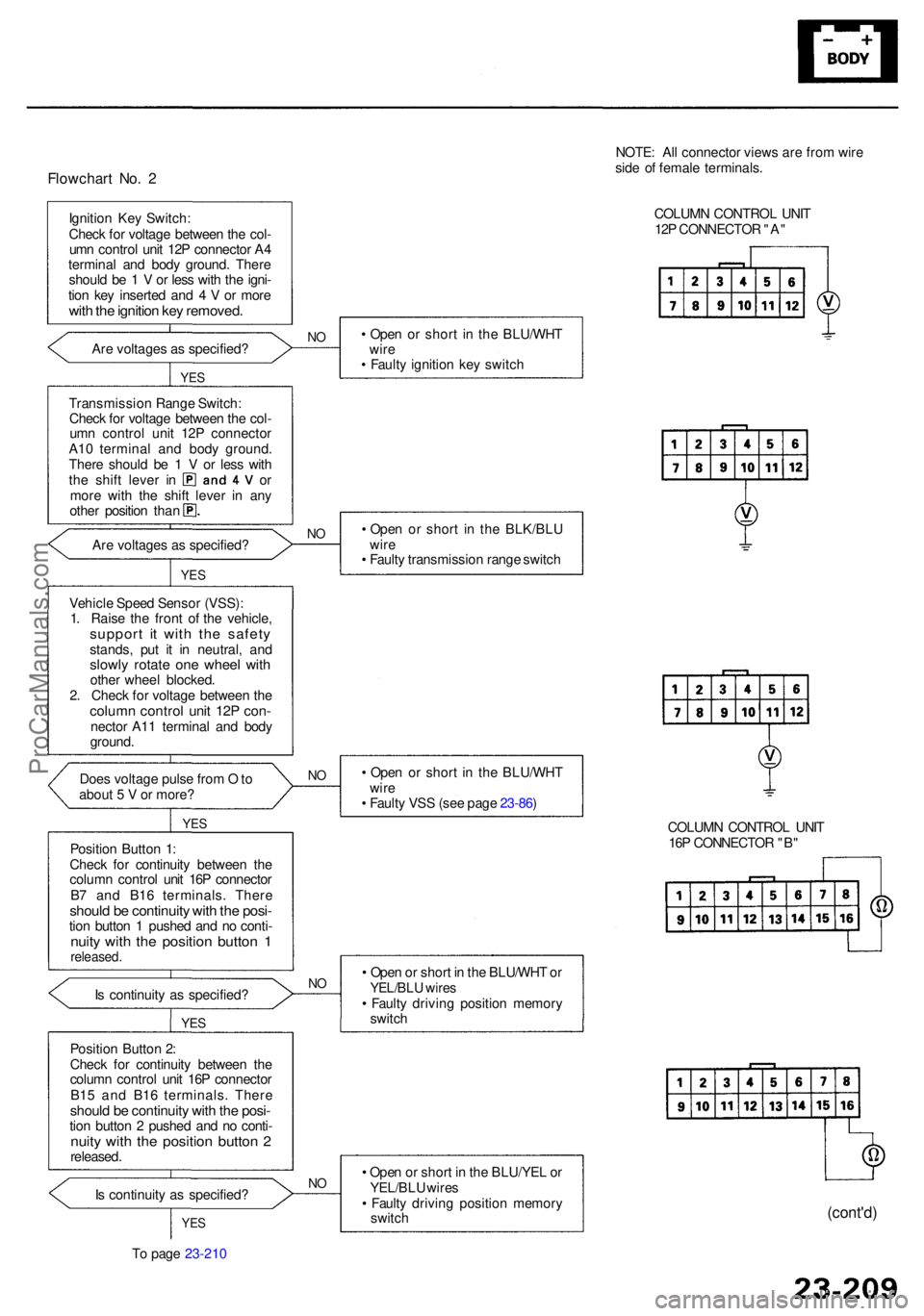
Flowchart No . 2
Ignitio n Ke y Switch :
Chec k fo r voltag e betwee n th e col -
um n contro l uni t 12 P connecto r A 4
termina l an d bod y ground . Ther e
shoul d b e 1 V or les s wit h th e igni -
tio n ke y inserte d an d 4 V or mor e
with th e ignitio n ke y removed .
Are voltages as specified ? •
Ope n o r shor t i n th e BLU/WH T
wir e
• Fault y ignitio n ke y switc hNO
YE S
Transmissio n Rang e Switch :
Chec k fo r voltag e betwee n th e col -
um n contro l uni t 12 P connecto r
A1 0 termina l an d bod y ground .
Ther e shoul d b e 1 V or les s wit h
the shif t leve r i n o r
mor e wit h th e shif t leve r i n an y
othe r positio n tha n
Ar e voltage s a s specified ? •
Ope n o r shor t i n th e BLK/BL U
wir e
• Fault y transmissio n rang e switc h
NO
YE S
Vehicl e Spee d Senso r (VSS) :
1 . Rais e th e fron t o f th e vehicle ,
support i t wit h th e safet ystands, pu t i t i n neutral , an dslowl y rotat e on e whee l wit hothe r whee l blocked .
2 . Chec k fo r voltag e betwee n th e
colum n contro l uni t 12 P con -necto r A1 1 termina l an d bod y
ground .
• Ope n o r shor t i n th e BLU/WH T
wir e
• Fault y VS S (se e pag e 23-86 )
Doe
s voltag e puls e fro m O to
abou t 5 V or more ?
NO
YE S
Positio n Butto n 1 :
Chec k fo r continuit y betwee n th e
colum n contro l uni t 16 P connecto r
B 7 an d B1 6 terminals . Ther e
should b e continuit y wit h th e posi -tion butto n 1 pushe d an d n o conti -nuity wit h th e positio n butto n 1released .
Is continuit y a s specified ? •
Ope n o r shor t i n th e BLU/WH T o rYEL/BL U wire s• Fault y drivin g positio n memor y
switc h
NO
YE S
Positio n Butto n 2 :
Chec k fo r continuit y betwee n th e
colum n contro l uni t 16 P connecto r
B1 5 an d B1 6 terminals . Ther e
should b e continuit y wit h th e posi -tion butto n 2 pushe d an d n o conti -nuity wit h th e positio n butto n 2released .
I s continuit y a s specified ?
NO• Ope n o r shor t i n th e BLU/YE L o r
YEL/BL U wire s
• Fault y drivin g positio n memor y
switc h
YES
To pag e 23-210 NOTE
: Al l connecto r view s ar e fro m wir e
sid e o f femal e terminals .
COLUM N CONTRO L UNI T
12 P CONNECTO R "A "
COLUM N CONTRO L UNI T
16 P CONNECTO R "B "
(cont'd )
ProCarManuals.com
Page 1613 of 1954
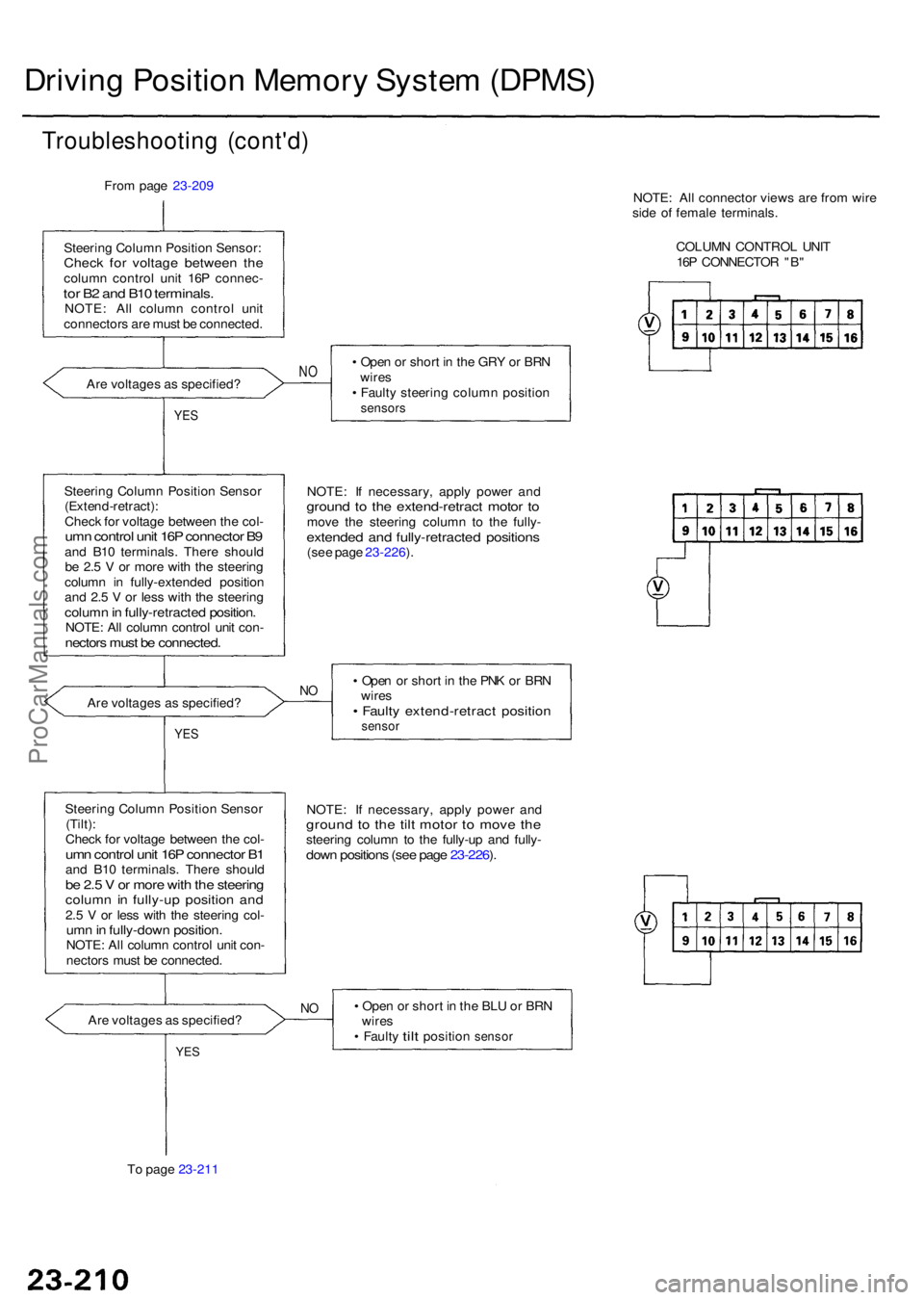
Driving Positio n Memor y Syste m (DPMS )
Troubleshootin g (cont'd )
From pag e 23-209
Steerin g Colum n Positio n Sensor :
Check fo r voltag e betwee n th ecolum n contro l uni t 16 P connec -tor B 2 an d B1 0 terminals .NOTE: Al l colum n contro l uni t
connector s ar e mus t b e connected .
Ar e voltage s a s specified ? •
Ope n o r shor t i n th e GR Y o r BR N
wire s
• Fault y steerin g colum n positio n
sensors
NO
YE S
NOTE : I f necessary , appl y powe r an dgroun d t o th e extend-retrac t moto r t omov e th e steerin g colum n t o th e fully -extende d an d fully-retracte d position s(see pag e 23-226 ).
Steerin
g Colum n Positio n Senso r
(Extend-retract) :
Chec k fo r voltag e betwee n th e col -umn contro l uni t 16 P connecto r B 9an d B1 0 terminals . Ther e shoul d
b e 2. 5 V or mor e wit h th e steerin g
colum n i n fully-extende d positio n
an d 2. 5 V or les s wit h th e steerin g
column in fully-retracte d position .NOTE: Al l colum n contro l uni t con -nector s mus t b e connected .
• Ope n o r shor t i n th e PN K o r BR N
wire s
• Fault y extend-retrac t positio nsensor
NOAr e voltage s a s specified ?
YES
NOTE : I f necessary , appl y powe r an dgroun d t o th e til t moto r t o mov e th esteerin g colum n t o th e fully-u p an d fully -down position s (se e pag e 23-226 ).
Steerin g Colum n Positio n Senso r
(Tilt) :
Chec k fo r voltag e betwee n th e col -
umn contro l uni t 16 P connecto r B 1an d B1 0 terminals . Ther e shoul dbe 2. 5 V or mor e wit h th e steerin gcolumn i n fully-u p positio n an d2.5 V or les s wit h th e steerin g col -umn in fully-dow n position .NOTE: Al l colum n contro l uni t con -
nector s mus t b e connected .
Ar e voltage s a s specified ?
NO• Ope n o r shor t i n th e BL U o r BR N
wire s
• Fault y tilt positio n sensor
To page 23-211
YES
NOTE : Al l connecto r view s ar e fro m wir e
sid e o f femal e terminals .
COLUM N CONTRO L UNI T
16 P CONNECTO R "B "
ProCarManuals.com
Page 1614 of 1954
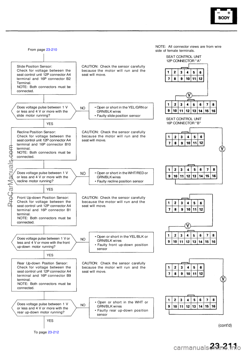
From pag e 23-210
CAUTION: Chec k th e senso r carefull y
becaus e th e moto r wil l ru n an d th e
sea t wil l move .
Slid
e Positio n Sensor :
Chec k fo r voltag e betwee n th e
sea t contro l uni t 12 P connecto r A 4
termina l an d 16 P connecto r B 2
Terminal .
NOTE : Bot h connector s mus t b e
connected . NOTE
: Al l connecto r view s ar e fro m wir e
sid e o f femal e terminals .
SEA T CONTRO L UNI T
12P CONNECTO R "A "
Doe s voltag e puls e betwee n 1 V
o r les s an d 4 V or mor e wit h th e
slid e moto r running ? •
Ope n o r shor t i n th e YEL/GR N o r
GRN/BL K wire s
• Fault y slid e positio n senso rNO
YE S
Reclin e Positio n Sensor :
Chec k fo r voltag e betwee n th e
sea t contro l uni t 12 P connecto r A 4termina l an d 16 P connecto r B1 0
terminal .
NOTE : Bot h connector s mus t b e
connected . CAUTION
: Chec k th e senso r carefully
becaus e th e moto r wil l ru n an d th esea t wil l move .
• Ope n o r shor t i n th e WHT/RE D o r
GRN/BL K wire s
• Fault y reclin e positio n senso r
NODoe s voltag e puls e betwee n 1 V
o r les s an d 4 V or mor e wit h th e
reclin e moto r running ?
Front Up-dow n Positio n Sensor :
Chec k fo r voltag e betwee n th e
sea t contro l uni t 12 P connecto r A 4
termina l an d 16 P connecto r B 1
terminal .
NOTE : Bot h connector s mus t b e
connected .
YES
CAUTION : Chec k th e senso r carefullybecaus e th e moto r wil l ru n an d th esea t wil l move .
Doe s voltag e puls e betwee n 1 V or
les s an d 4 V or mor e wit h th e fron t
up-dow n moto r running ?
NO• Ope n o r shor t i n th e YEL/BL K o r
GRN/BL K wire s
• Fault y fron t up-dow n positio n
sensor
YES
CAUTION : Chec k th e senso r carefull y
becaus e th e moto r wil l ru n an d th e
sea t wil l move .
Rea
r Up-dow n Positio n Sensor :
Chec k fo r voltag e betwee n th e
sea t contro l uni t 12 P connecto r A 4
termina l an d 16 P connecto r B 9
terminal .
NOTE : Bot h connector s mus t b e
connected .
• Ope n o r shor t i n th e WH T o r
GRN/BL K wire s
• Fault y rea r up-dow n positio n
sensor
NODoe s voltag e puls e betwee n 1 V
o r les s an d 4 V or mor e wit h th e
rea r up-dow n moto r running ?
YES
To pag e 23-212
(cont'd )
SEAT CONTRO L UNI T
16 P CONNECTO R "B "
ProCarManuals.com
Page 1615 of 1954
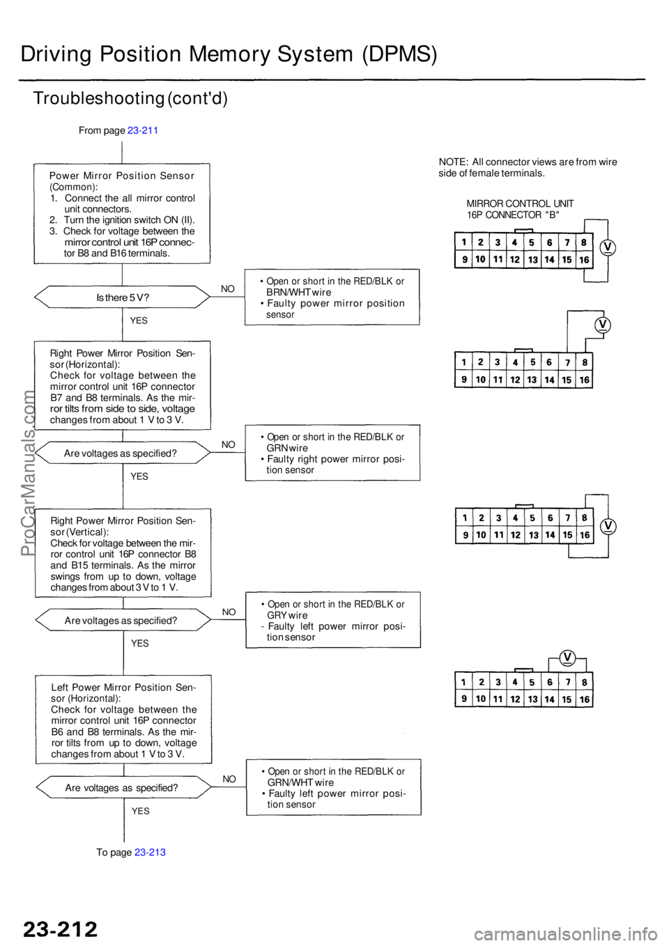
Driving Positio n Memor y Syste m (DPMS )
Troubleshootin g (cont'd )
From pag e 23-211
Powe r Mirro r Positio n Senso r
(Common) :1. Connec t th e al l mirro r contro l
uni t connectors .
2 . Tur n th e ignitio n switc h O N (II) .
3 . Chec k fo r voltag e betwee n th e
mirro r contro l uni t 16 P connec -tor B 8 an d B1 6 terminals .
Is ther e 5 V ?NO• Ope n o r shor t i n th e RED/BL K o rBRN/WH T wir e
• Fault y powe r mirro r positio n
sensorYES
Righ t Powe r Mirro r Positio n Sen -
so r (Horizontal) :
Chec k fo r voltag e betwee n th e
mirro r control unit 16 P connecto r
B 7 an d B 8 terminals . A s th e mir -
ror tilt s fro m sid e to side , voltag echange s fro m abou t 1 V to 3 V .
• Ope n o r shor t i n th e RED/BL K o rGR N wir e
• Fault y righ t powe r mirro r posi -
tion senso r
Are voltage s a s specified ?NO
YE S
Righ t Powe r Mirro r Positio n Sen -
so r (Vertical) :
Chec k fo r voltag e betwee n th e mir -
ro r contro l uni t 16 P connecto r B 8
an d B1 5 terminals . A s th e mirro r
swing s fro m u p t o down , voltag e
change s fro m abou t 3 V to 1 V .
Ar e voltage s a s specified ?
• Ope n o r shor t i n th e RED/BL K o rGR Y wir e
- Fault y lef t powe r mirro r posi -
tio n senso rNO
YE S
Lef t Powe r Mirro r Positio n Sen -sor (Horizontal) :Check fo r voltag e betwee n th e
mirro r contro l uni t 16 P connecto r
B 6 an d B 8 terminals . A s th e mir -
ro r tilt s fro m u p t o down , voltag e
change s fro m abou t 1 V to 3 V .
Ar e voltage s a s specified ?
NO• Ope n o r shor t i n th e RED/BL K o rGRN/WH T wir e
• Fault y lef t powe r mirro r posi -
tion senso rYES
To pag e 23-213 NOTE
: Al l connecto r view s ar e fro m wir e
sid e o f femal e terminals .
MIRROR CONTRO L UNI T16P CONNECTO R "B "
ProCarManuals.com
Page 1616 of 1954
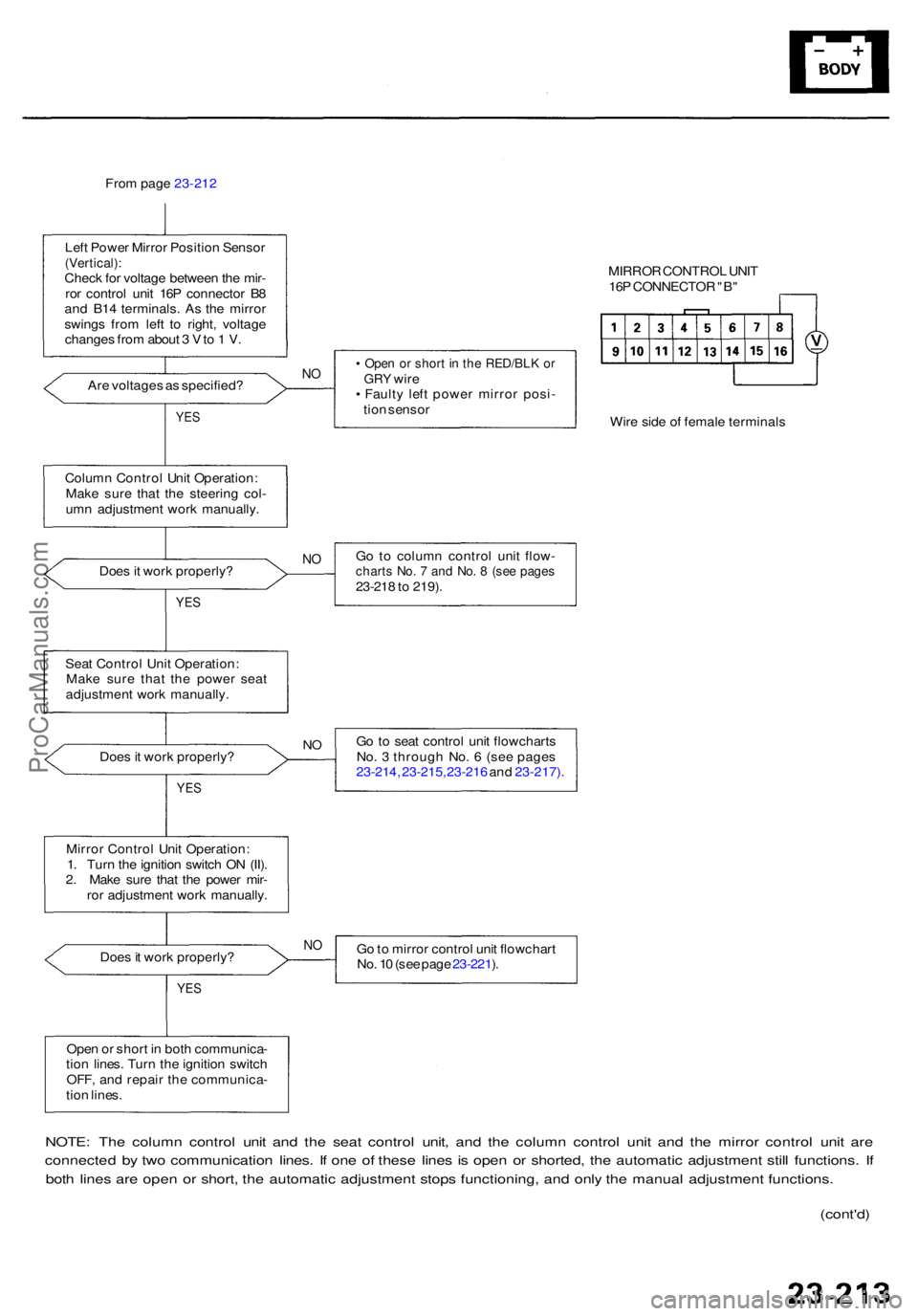
From pag e 23-212
Lef t Powe r Mirro r Positio n Senso r
(Vertical) :Check fo r voltag e betwee n th e mir -
ro r contro l uni t 16 P connecto r B 8
an d B1 4 terminals . A s th e mirro r
swing s fro m lef t t o right , voltag e
change s fro m abou t 3 V to 1 V .
Ar e voltage s a s specified ?
NO• Ope n o r shor t i n th e RED/BL K o rGR Y wir e
• Fault y lef t powe r mirro r posi -
tio n senso r
YES
Colum n Contro l Uni t Operation :
Mak e sur e tha t th e steerin g col -
um n adjustmen t wor k manually .
Doe s it wor k properly ?
NOG o t o colum n contro l uni t flow -chart s No . 7 an d No . 8 (se e page s23-218 to 219) .YES
Sea t Contro l Uni t Operation :
Mak e sur e tha t th e powe r sea t
adjustmen t wor k manually .
Go to sea t contro l uni t flowchart s
No . 3 throug h No . 6 (se e page s
23-21 4, 23-215, 23-216 and 23-217) .
NODoe s it wor k properly ?
YES
Mirro r Contro l Uni t Operation :
1 . Tur n th e ignitio n switc h O N (II) .
2 . Mak e sur e tha t th e powe r mir -
ro r adjustmen t wor k manually .
Doe s it wor k properly ? G
o to mirro r contro l uni t flowchar t
No . 1 0 (se e pag e 23-221 ).
N O
YE S
Ope n o r shor t i n bot h communica -
tio n lines . Tur n th e ignitio n switc h
OFF , an d repai r th e communica -
tio n lines .
NOTE : Th e colum n contro l uni t an d th e sea t contro l unit , an d th e colum n contro l uni t an d th e mirro r contro l uni t ar e
connecte d b y tw o communicatio n lines . I f on e o f thes e line s i s ope n o r shorted , th e automati c adjustmen t stil l functions . I f
bot h line s ar e ope n o r short , th e automati c adjustment stops functioning , an d onl y th e manua l adjustmen t functions .
(cont'd )
MIRRO R CONTRO L UNI T
16 P CONNECTO R "B "
Wir e sid e o f femal e terminal s
ProCarManuals.com
Page 1617 of 1954
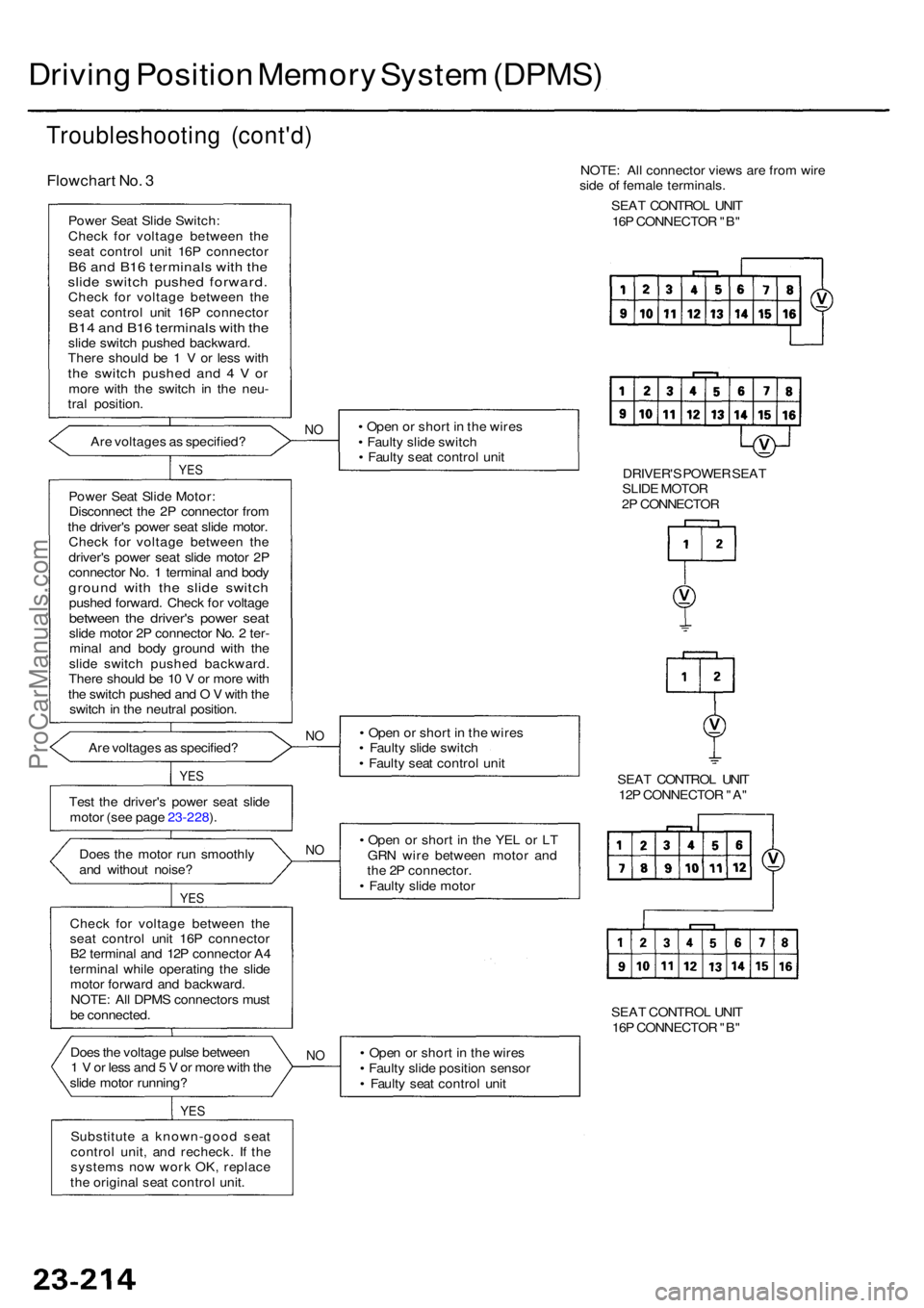
Driving Positio n Memor y Syste m (DPMS )
Troubleshootin g (cont'd )
Flowchar t No . 3
Powe r Sea t Slid e Switch :
Chec k fo r voltag e betwee n th e
sea t contro l uni t 16 P connecto r
B6 an d B1 6 terminal s wit h th eslid e switc h pushe d forward .Check fo r voltag e betwee n th e
sea t contro l uni t 16 P connecto r
B14 an d B1 6 terminal s wit h th eslid e switc h pushe d backward .
Ther e shoul d b e 1 V or les s wit h
the switc h pushe d an d 4 V ormor e wit h th e switc h i n th e neu -
tra l position .
Ar e voltage s a s specified ?
NO• Ope n o r shor t i n th e wire s
• Fault y slid e switc h
• Fault y sea t contro l uni t
YES
Powe r Sea t Slid e Motor :
Disconnec t th e 2 P connecto r fro m
th e driver' s powe r sea t slid e motor .
Chec k fo r voltag e betwee n th e
driver' s powe r sea t slid e moto r 2 P
connecto r No . 1 termina l an d bod y
groun d wit h th e slid e switc hpushed forward . Chec k fo r voltag ebetwee n th e driver' s powe r sea tslide moto r 2 P connecto r No . 2 ter -
mina l an d bod y groun d wit h th e
slid e switc h pushe d backward .
Ther e shoul d b e 1 0 V or mor e wit h
th e switc h pushe d an d O V wit h th e
switc h in th e neutra l position .
Ar e voltage s a s specified ?
NO• Ope n o r shor t i n th e wire s
• Fault y slid e switc h
• Fault y sea t contro l uni t
Tes t th e driver' s powe r sea t slid e
moto r (se e pag e 23-228 ).
N O• Ope n o r shor t i n th e YE L o r L T
GR N wir e betwee n moto r an d
th e 2 P connector .
• Fault y slid e moto r
Doe
s th e moto r ru n smoothl y
an d withou t noise ?
Chec k fo r voltag e betwee n th e
sea t contro l uni t 16 P connecto r
B 2 termina l an d 12 P connecto r A 4
termina l whil e operatin g th e slid e
moto r forwar d an d backward .
NOTE : Al l DPM S connector s mus t
b e connected .
YES
YES
Doe s th e voltag e puls e betwee n
1 V or les s an d 5 V or mor e wit h th e
slid e moto r running ? •
Ope n o r shor t i n th e wire s
• Fault y slid e positio n senso r
• Fault y sea t contro l uni tNO
YE S
Substitut e a known-goo d sea t
contro l unit , an d recheck . I f th e
system s no w wor k OK , replac e
th e origina l sea t contro l unit . SEA
T CONTRO L UNI T
16 P CONNECTO R "B "
SEA
T CONTRO L UNI T
12 P CONNECTO R "A "
NOTE
: Al l connecto r view s ar e fro m wire
sid e o f femal e terminals .
SEA T CONTRO L UNI T
16 P CONNECTO R "B "
DRIVER' S POWE R SEA T
SLID E MOTO R
2 P CONNECTO R
ProCarManuals.com
Page 1618 of 1954
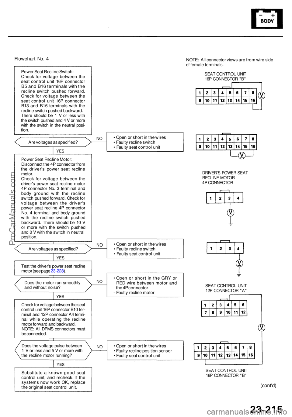
Flowchart No . 4
Powe r Sea t Reclin e Switch :
Chec k fo r voltag e betwee n th e
sea t contro l uni t 16 P connecto r
B5 an d B1 6 terminal s wit h th ereclin e switc h pushe d forward .
Chec k fo r voltag e betwee n th e
sea t contro l uni t 16 P connecto r
B1 3 an d B1 6 terminal s wit h th e
reclin e switc h pushe d backward .
Ther e shoul d b e 1 V or les s wit h
th e switc h pushe d an d 4 V or mor e
wit h th e switc h in th e neutra l posi -
tion.
Are voltage s a s specified ?NO• Ope n o r shor t i n th e wire s
• Fault y reclin e switc h
• Fault y sea t contro l uni t
YES
Powe r Sea t Reclin e Motor :
Disconnec t th e 4 P connecto r fro m
th e driver' s powe r sea t reclin e
motor .
Chec k fo r voltag e betwee n th e
driver' s powe r sea t reclin e moto r
4 P connecto r No . 3 termina l an d
bod y groun d wit h th e reclin e
switc h pushe d forward . Chec k fo r
voltag e betwee n th e driver' s
powe r sea t reclin e 4 P connecto r
No . 4 termina l an d bod y groun d
wit h th e reclin e switc h pushe d
backward . Ther e shoul d b e 1 0 V
o r mor e wit h th e switc h pushe d
an d 0 V wit h th e switc h in neutra l
position .
Ar e voltage s a s specified ? •
Ope n o r shor t i n th e wire s
• Fault y reclin e switc h
• Fault y sea t contro l uni t
NO
YE S
NO• Ope n o r shor t i n th e GR Y o r
RE D wir e betwee n moto r an d
th e 4 P connector .
- Fault y reclin e moto r
Tes
t th e driver' s powe r sea t reclin e
moto r (se e pag e 23-228 ).
Doe s th e moto r ru n smoothl y
an d withou t noise ?
YES
Chec k fo r voltag e betwee n th e sea t
contro l uni t 16 P connecto r B1 0 ter -
mina l an d 12 P connecto r A 4 termi -
na l whil e operatin g th e reclin e
moto r forwar d an d backward .
NOTE : Al l DPM S connector s mus t
b e connected .
I
Does th e voltag e puls e betwee n
1 V or les s an d 5 V or mor e wit h
th e reclin e moto r running ?NO• Ope n o r shor t i n th e wire s
• Fault y reclin e positio n senso r
• Fault y sea t contro l uni t
Substitut e a known-goo d sea t
contro l unit , an d recheck . I f th esystem s no w wor k OK , replac e
th e origina l sea t contro l unit .
YES
SEA T CONTRO L UNI T16P CONNECTO R "B "
DRIVER' S POWE R SEA TRECLIN E MOTO R4P CONNECTO R
NOTE: Al l connecto r view s ar e fro m wire side
o f femal e terminals .
SEAT CONTRO L UNI T16P CONNECTO R "B "
SEA T CONTRO L UNI T12P CONNECTO R "A "
(cont'd )
ProCarManuals.com
Page 1619 of 1954
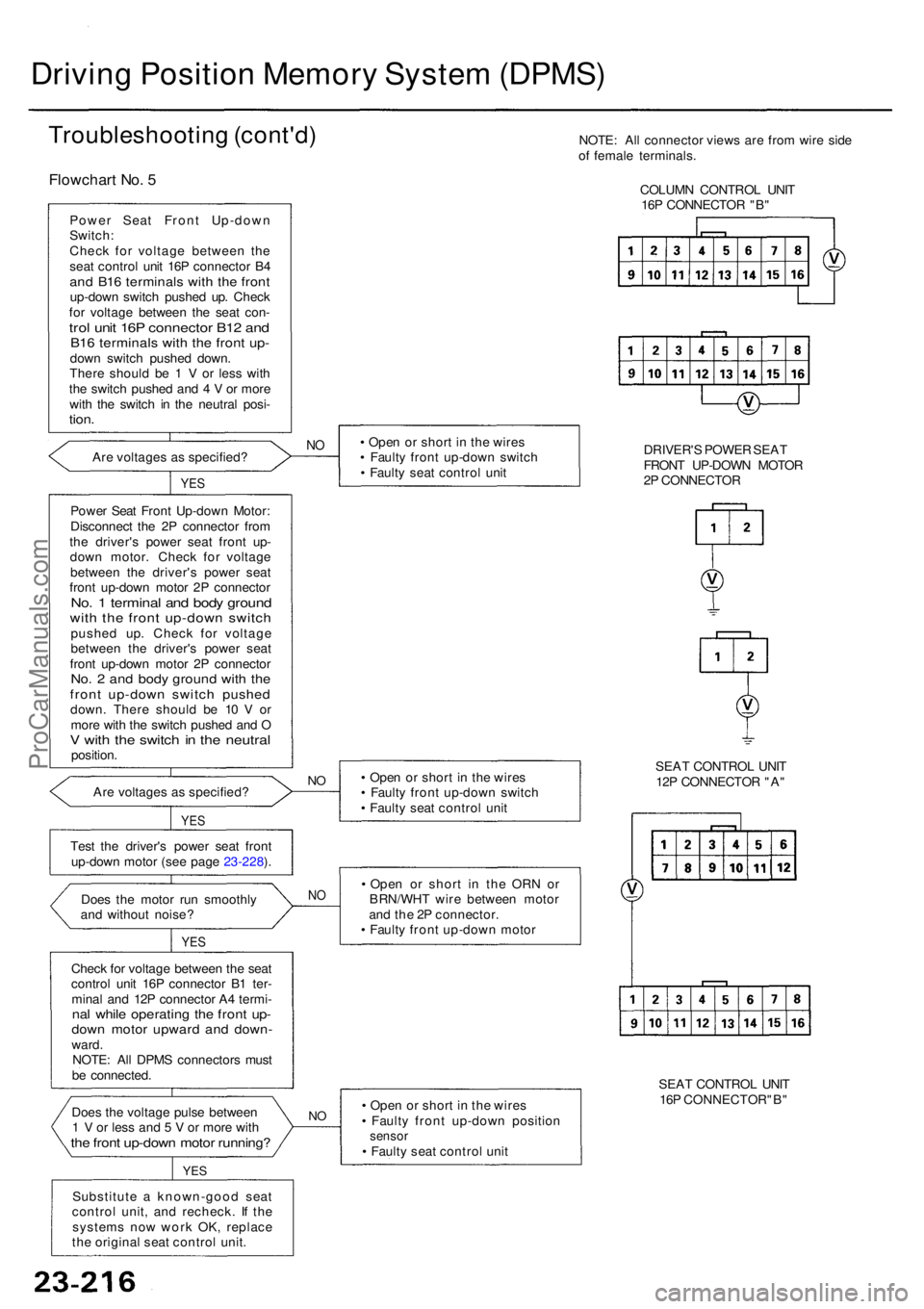
• Ope n o r shor t i n th e wire s
• Fault y fron t up-dow n positio n
sensor• Fault y sea t contro l uni t
Substitut e a known-goo d sea t
contro l unit , an d recheck . I f th e
system s no w wor k OK , replac e
th e origina l sea t contro l unit .
Doe
s th e voltag e puls e betwee n
1 V or les s an d 5 V or mor e wit hthe fron t up-dow n moto r running ?
YES
NO
Chec k fo r voltag e betwee n th e sea t
contro l uni t 16 P connecto r B 1 ter -
mina l an d 12 P connecto r A 4 termi -
nal whil e operatin g th e fron t up -dow n moto r upwar d an d down -ward.
NOTE : Al l DPM S connector s mus t
b e connected .
Doe
s th e moto r ru n smoothl y
an d withou t noise ?
YES
NO• Ope n o r shor t i n th e OR N o r
BRN/WH T wir e betwee n moto r
an d th e 2 P connector .
• Fault y fron t up-dow n moto r
Tes
t th e driver' s powe r sea t fron t
up-dow n moto r (se e pag e 23-228 ). •
Ope n o r shor t i n th e wire s
• Fault y fron t up-dow n switc h
• Fault y sea t contro l uni t
NOAr e voltage s a s specified ?
YES
Powe r Sea t Fron t Up-dow n Motor :
Disconnec t th e 2 P connecto r fro m
th e driver' s powe r sea t fron t up -
dow n motor . Chec k fo r voltag e
betwee n th e driver' s powe r sea t
fron t up-dow n moto r 2 P connecto r
No. 1 termina l an d bod y groun dwith th e fron t up-dow n switc hpushe d up . Chec k fo r voltag e
betwee n th e driver' s powe r sea t
fron t up-dow n moto r 2 P connecto r
No. 2 an d bod y groun d wit h th efron t up-dow n switc h pushe ddown. Ther e shoul d b e 1 0 V or
mor e wit h th e switc h pushe d an d O
V wit h th e switc h in th e neutra lposition . •
Ope n o r shor t i n th e wire s
• Fault y fron t up-dow n switc h
• Fault y sea t contro l uni t
NO
YE S
Are voltage s a s specified ?
Powe
r Sea t Fron t Up-dow n
Switch :
Chec k fo r voltag e betwee n th e
sea t contro l uni t 16 P connecto r B 4
an d B1 6 terminal s wit h th e fron tup-dow n switc h pushe d up . Chec k
fo r voltag e betwee n th e sea t con -
trol uni t 16 P connecto r B1 2 an dB16 terminal s wit h th e fron t up -dow n switc h pushe d down .
Ther e shoul d b e 1 V or les s wit h
th e switc h pushe d an d 4 V or mor e
wit h th e switc h i n th e neutra l posi -
tion.
Flowchar t No . 5
Troubleshootin g (cont'd )
Driving Positio n Memor y Syste m (DPMS )
NOTE: Al l connecto r view s ar e fro m wir e sid e
o f femal e terminals .
COLUM N CONTRO L UNI T
16 P CONNECTO R "B "
DRIVER' S POWE R SEA T
FRON T UP-DOW N MOTO R
2 P CONNECTO R
SEA T CONTRO L UNI T
12 P CONNECTO R "A "
SEA T CONTRO L UNI T
16 P CONNECTOR"B "
ProCarManuals.com
Page 1620 of 1954
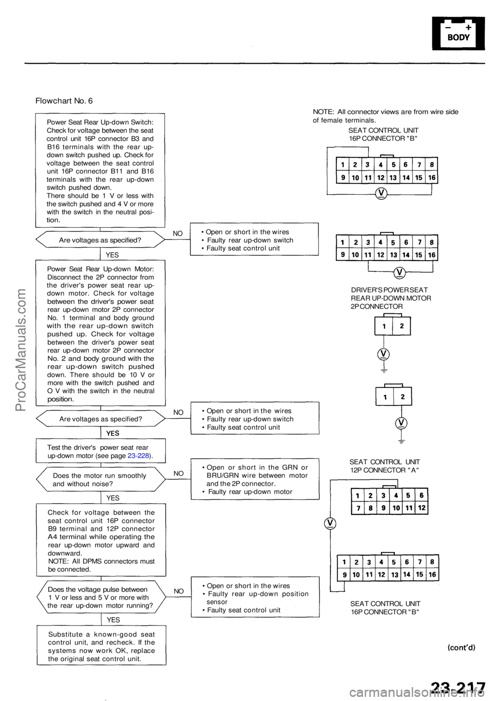
Flowchart No . 6
Powe r Sea t Rea r Up-dow n Switch :
Chec k fo r voltag e betwee n th e sea t
contro l uni t 16 P connecto r B 3 an d
B1 6 terminal s wit h th e rea r up -
dow n switc h pushe d up . Chec k fo r
voltag e betwee n th e sea t contro l
uni t 16 P connecto r B1 1 an d B1 6
terminal s wit h th e rea r up-dow n
switc h pushe d down .
Ther e shoul d b e 1 V or les s wit h
th e switc h pushe d an d 4 V or mor e
wit h th e switc h i n th e neutra l posi -
tion.
Are voltage s a s specified ?NO• Ope n o r shor t i n th e wire s
• Fault y rea r up-dow n switc h
• Fault y sea t contro l uni t
YES
Powe r Sea t Rea r Up-dow n Motor :
Disconnec t th e 2 P connecto r fro m
th e driver' s powe r sea t rea r up -
dow n motor . Chec k fo r voltag e
between th e driver' s powe r sea trear up-dow n moto r 2 P connecto r
No . 1 termina l an d bod y groun d
with th e rea r up-dow n switc hpushed up . Chec k fo r voltag ebetwee n th e driver' s powe r sea t
rea r up-dow n moto r 2 P connecto r
No. 2 an d bod y groun d wit h th erea r up-dow n switc h pushe ddown. Ther e shoul d b e 1 0 V or
mor e wit h th e switc h pushe d an d
O V wit h th e switc h i n th e neutra l
position.
Are voltage s a s specified ?NO• Ope n o r shor t i n th e wire s
• Fault y rea r up-dow n switc h
• Fault y sea t contro l uni t
Tes t th e driver' s powe r sea t rea r
up-dow n moto r (se e pag e 23-228 ).
Doe s th e moto r ru n smoothl y
an d withou t noise ? •
Ope n o r shor t i n th e GR N o r
BRU/GR N wir e betwee n moto r
an d th e 2 P connector .
• Fault y rea r up-dow n moto r
NO
YE S
Chec k fo r voltag e betwee n th e
sea t contro l uni t 16 P connecto r
B 9 termina l an d 12 P connecto r
A4 termina l whil e operatin g th erea r up-dow n moto r upwar d an d
downward .
NOTE : Al l DPM S connector s mus t
b e connected .
• Ope n o r shor t i n th e wire s
• Fault y rea r up-dow n positio n
sensor• Fault y sea t contro l uni t
NODoe s th e voltag e puls e betwee n1 V or les s an d 5 V or mor e wit h
th e rea r up-dow n moto r running ?
YES
Substitut e a known-goo d sea t
contro l unit , an d recheck . I f th e
system s no w wor k OK , replac e
th e origina l sea t contro l unit . SEA
T CONTRO L UNI T
16 P CONNECTO R "B "
SEA
T CONTRO L UNI T
12 P CONNECTO R "A "
NOTE : Al l connecto r view s ar e fro m wir e sid eof femal e terminals .
SEA T CONTRO L UNI T
16 P CONNECTO R "B "
DRIVER' S POWE R SEA T
REA R UP-DOW N MOTO R
2 P CONNECTO R
ProCarManuals.com