ACURA RL KA9 1996 Service Repair Manual
Manufacturer: ACURA, Model Year: 1996, Model line: RL KA9, Model: ACURA RL KA9 1996Pages: 1954, PDF Size: 61.44 MB
Page 1921 of 1954
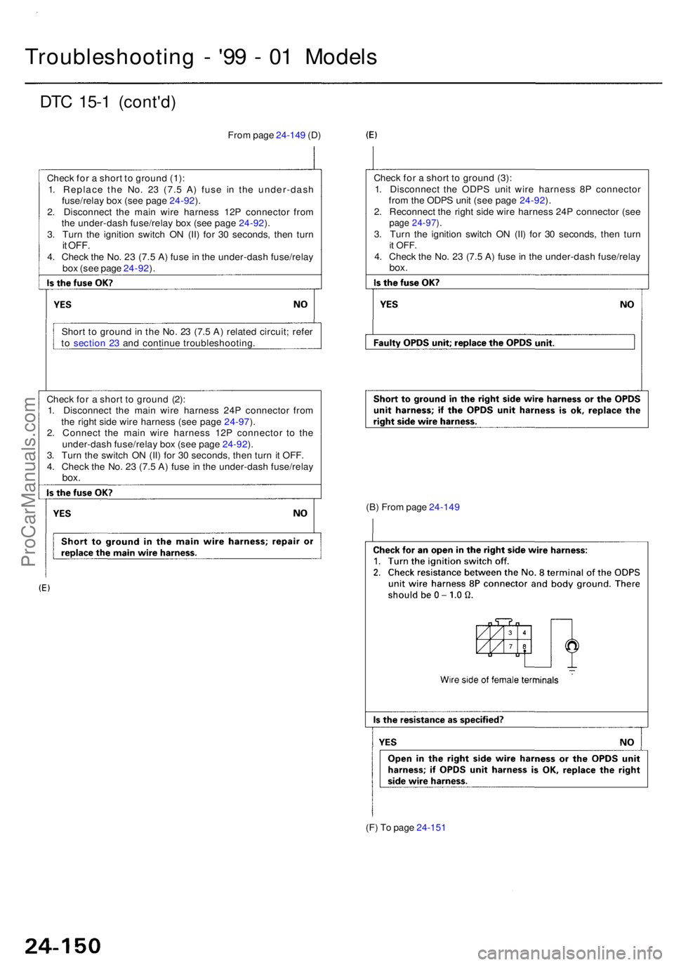
Troubleshooting - '9 9 - 0 1 Model s
DTC 15- 1 (cont'd )
From pag e 24-14 9 (D )
Chec k fo r a shor t t o groun d (1) :
1 . Replac e th e No . 2 3 (7. 5 A ) fus e i n th e under-das h
fuse/rela y bo x (se e pag e 24-92 ).
2 . Disconnec t th e mai n wir e harnes s 12 P connecto r fro m
th e under-das h fuse/rela y bo x (se e pag e 24-92 ).
3 . Tur n th e ignitio n switc h O N (II ) fo r 3 0 seconds , the n tur n
it OFF .4. Chec k th e No . 2 3 (7. 5 A ) fus e in th e under-das h fuse/rela y
bo x (se e pag e 24-92 ).
Shor t t o groun d in th e No . 2 3 (7. 5 A ) relate d circuit ; refe r
t o sectio n 2 3 an d continu e troubleshooting . Chec
k fo r a shor t t o groun d (3) :
1 . Disconnec t th e ODP S uni t wir e harnes s 8 P connecto r
fro m th e ODP S uni t (se e pag e 24-92 ).
2 . Reconnec t th e righ t sid e wir e harnes s 24 P connecto r (se e
page 24-97 ).3 . Tur n th e ignitio n switc h O N (II ) fo r 3 0 seconds , the n tur nit OFF .4. Chec k th e No . 2 3 (7. 5 A ) fus e in th e under-das h fuse/rela ybox.
Chec k fo r a shor t t o groun d (2) :
1 . Disconnec t th e mai n wir e harnes s 24 P connecto r fro m
th e righ t sid e wir e harnes s (se e pag e 24-97 ).
2 . Connec t th e mai n wir e harnes s 12 P connecto r t o th e
under-das h fuse/rela y bo x (se e pag e 24-92 ).
3 . Tur n th e switc h O N (II ) fo r 3 0 seconds , the n tur n i t OFF .
4 . Chec k th e No . 2 3 (7. 5 A ) fus e in th e under-das h fuse/rela y
box.
(B) Fro m pag e 24-14 9
(F ) T o pag e 24-15 1
ProCarManuals.com
Page 1922 of 1954
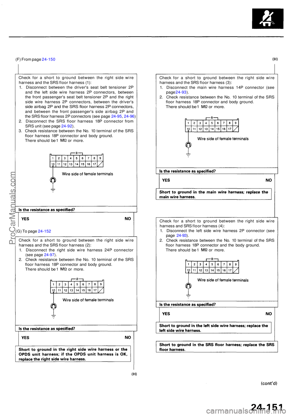
(F) Fro m pag e 24-15 0
Chec k fo r a shor t t o groun d betwee n th e righ t sid e wir e
harnes s an d th e SR S floo r harnes s (1) :
1 . Disconnec t betwee n th e driver' s sea t bel t tensione r 2 P
an d th e lef t sid e wir e harnes s 2 P connectors , betwee n
th e fron t passenger' s sea t bel t tensione r 2 P an d th e righ t
sid e wir e harnes s 2 P connectors , betwee n th e driver' s
side airba g 2 P an d th e SR S floo r harnes s 2 P connectors ,and betwee n th e fron t passenger' s sid e airba g 2 P an d
the SRS floor harness 2P connectors (see page 24-95, 24-96 )
2 . Disconnec t th e SR S floo r harnes s 18 P connecto r fro m
SR S uni t (se e pag e 24-92 ).
3 . Chec k resistanc e betwee n th e No . 1 0 termina l o f th e SR S
floo r harnes s 18 P connecto r an d bod y ground .
There shoul d b e 1 o r more . Chec
k fo r a shor t t o groun d betwee n th e righ t sid e wir e
harnes s an d th e SR S floo r harnes s (3) :
1 . Disconnec t th e mai n wir e harnes s 14 P connecto r (se e
pag e 24-93 ).
2 . Chec k resistanc e betwee n th e No . 1 0 termina l o f th e SR S
floo r harnes s 18 P connecto r an d bod y ground .
There shoul d b e 1 o r more .
(G) T o pag e 24-15 2
Chec k fo r a shor t t o groun d betwee n th e righ t sid e wir e
harnes s an d th e SR S floo r harnes s (2) :
1 . Disconnec t th e righ t sid e wir e harnes s 24 P connecto r
(see pag e 24-97 ).2 . Chec k resistanc e betwee n th e No . 1 0 termina l o f th e SR S
floo r harnes s 18 P connecto r an d bod y ground .
There shoul d b e 1 o r more . Chec
k fo r a shor t t o groun d betwee n th e righ t sid e wir e
harnes s an d SR S floo r harnes s (4) :
1 . Disconnec t th e lef t sid e wir e harnes s 2 P connecto r (se e
pag e 24-93 ).
2 . Chec k resistanc e betwee n th e No . 1 0 termina l o f th e SR S
floo r harnes s 18 P connecto r an d th e bod y ground .
There shoul d b e 1 o r more .
ProCarManuals.com
Page 1923 of 1954
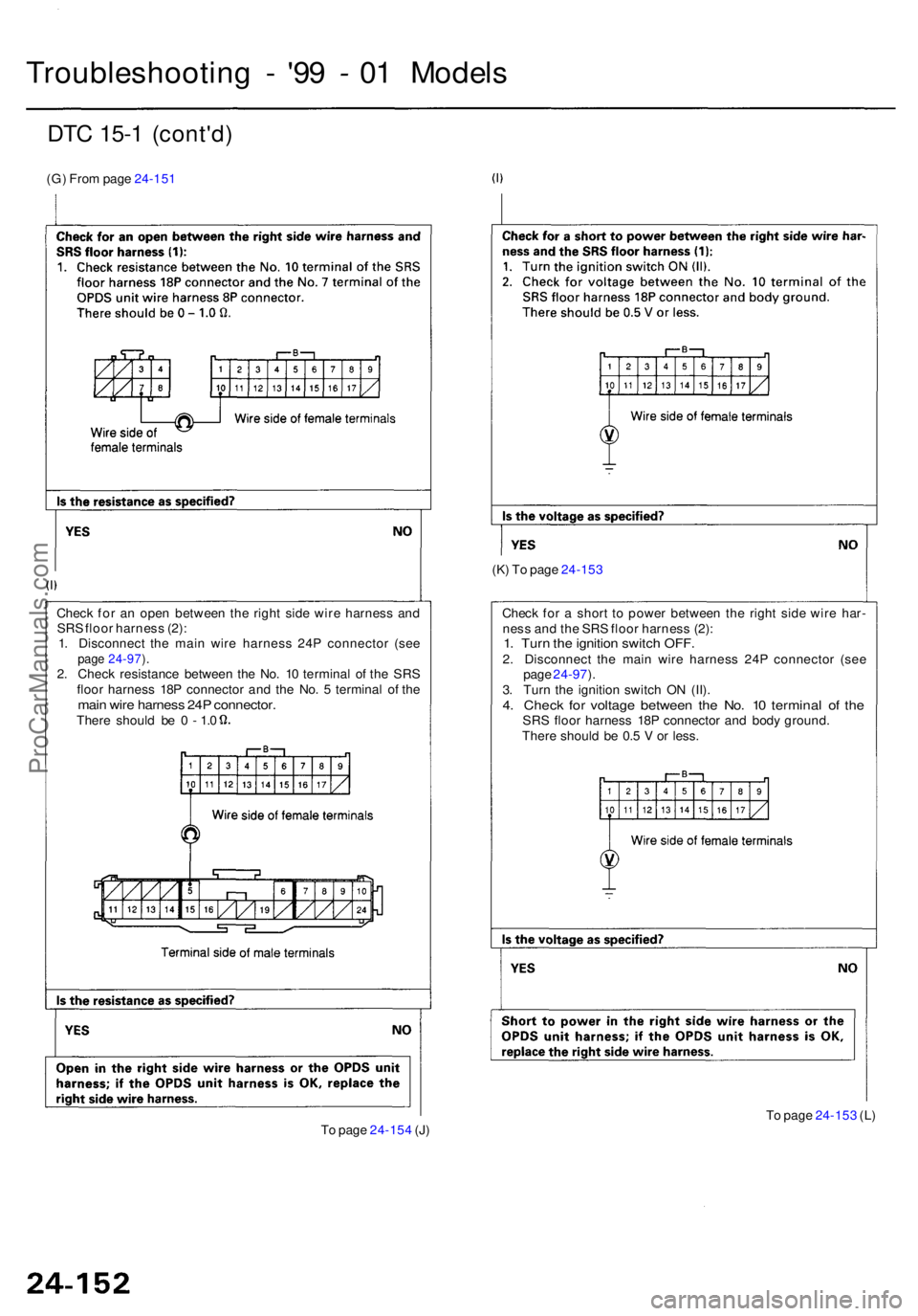
DTC 15- 1 (cont'd )
(G) Fro m pag e 24-15 1
Troubleshootin g - '9 9 - 0 1 Model s
(K) T o pag e 24-15 3
Chec k fo r a shor t t o powe r betwee n th e righ t sid e wir e har -
nes s an d th e SR S floo r harnes s (2) :
1. Tur n th e ignitio n switc h OFF .2. Disconnec t th e mai n wir e harnes s 24 P connecto r (se e
pag e 24-97 ).
3 . Tur n th e ignitio n switc h O N (II) .
4. Chec k fo r voltag e betwee n th e No . 1 0 termina l o f th eSR S floo r harnes s 18 P connecto r an d bod y ground .
Ther e shoul d b e 0. 5 V or less .
Chec
k fo r a n ope n betwee n th e righ t sid e wir e harnes s an d
SR S floo r harnes s (2) :
1 . Disconnec t th e mai n wir e harnes s 24 P connecto r (se e
page 24-97 ).2 . Chec k resistance between th e No . 1 0 termina l o f th e SR S
floo r harnes s 18 P connecto r an d th e No . 5 termina l o f th e
mai n wir e harnes s 24 P connector .There shoul d b e 0 - 1.0
To pag e 24-15 4 (J ) T
o pag e 24-15 3 (L )
ProCarManuals.com
Page 1924 of 1954
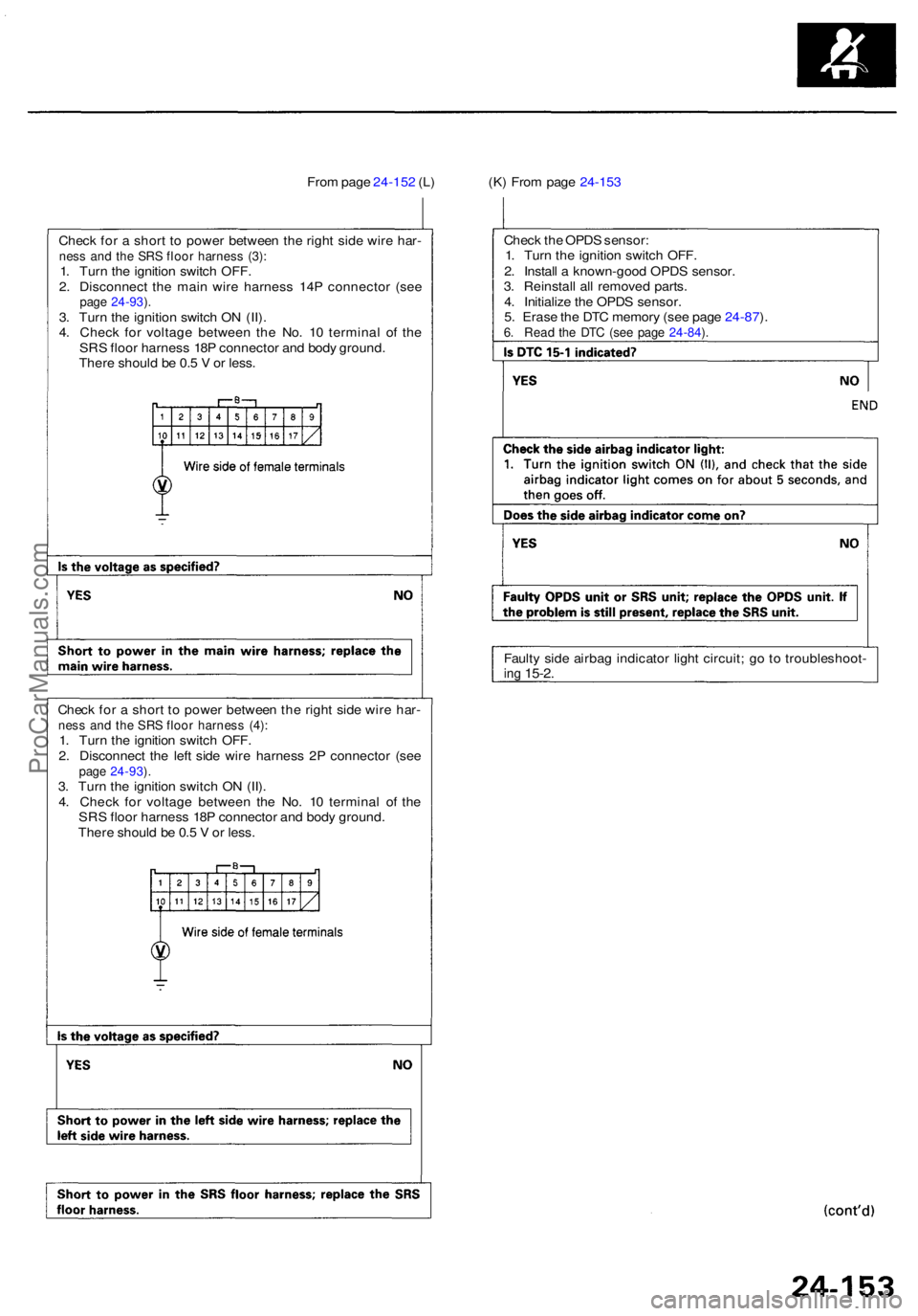
Check fo r a shor t t o powe r betwee n th e righ t sid e wir e har -ness an d th e SR S floo r harnes s (4) :1. Tur n th e ignitio n switc h OFF .
2 . Disconnec t th e lef t sid e wir e harnes s 2 P connecto r (se e
page 24-93 ).3 . Tur n th e ignitio n switc h O N (II) .
4 . Chec k fo r voltag e betwee n th e No . 1 0 termina l o f th e
SR S floo r harnes s 18 P connecto r an d bod y ground .
Ther e shoul d b e 0. 5 V or less . Fault
y sid e airba g indicato r ligh t circuit ; g o to troubleshoot -
ing 15-2 .
Chec k fo r a shor t t o powe r betwee n th e righ t sid e wir e har -ness an d th e SR S floo r harnes s (3) :1. Tur n th e ignitio n switc h OFF .
2 . Disconnec t th e mai n wir e harnes s 14 P connecto r (se e
page 24-93 ).3 . Tur n th e ignitio n switc h O N (II) .
4 . Chec k fo r voltag e betwee n th e No . 1 0 termina l o f th e
SR S floo r harnes s 18 P connecto r an d bod y ground .
Ther e shoul d b e 0. 5 V or less . Chec
k th e OPD S sensor :
1 . Tur n th e ignitio n switc h OFF .
2 . Instal l a known-goo d OPD S sensor .
3 . Reinstal l al l remove d parts .
4 . Initializ e th e OPD S sensor .
5 . Eras e th e DT C memor y (se e pag e 24-87 ).6 . Rea d th e DT C (se e pag e 24-84 ).
Fro m pag e 24-15 2 (L ) (K ) Fro m pag e 24-15 3
ProCarManuals.com
Page 1925 of 1954
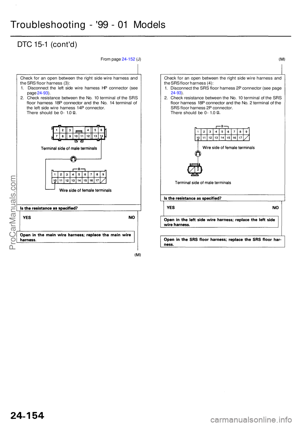
Check fo r a n ope n betwee n th e righ t sid e wir e harnes s an d
th e SR S floo r harnes s (3) :
1 . Disconnec t th e lef t sid e wir e harnes s H P connecto r (se e
pag e 24-93 ).
2 . Chec k resistanc e betwee n th e No . 1 0 termina l o f th e SR S
floor harnes s 18 P connecto r an d th e No . 1 4 termina l o fthe lef t sid e wir e harnes s 14 P connector .There shoul d b e 0 - 1. 0 Chec
k fo r a n ope n betwee n th e righ t sid e wir e harnes s an d
th e SR S floo r harnes s (4) :
1 . Disconnec t th e SR S floo r harnes s 2 P connecto r (se e pag e
24-93 ).2 . Chec k resistanc e betwee n th e No . 1 0 termina l o f th e SR Sfloor harnes s 18 P connecto r an d th e No . 2 termina l o f th eSR S floo r harnes s 2 P connector.Ther e shoul d b e 0 - 1. 0
Fro
m pag e 24-15 2 (J )
DT C 15- 1 (cont'd )
Troubleshootin g - '9 9 - 0 1 Model s
ProCarManuals.com
Page 1926 of 1954
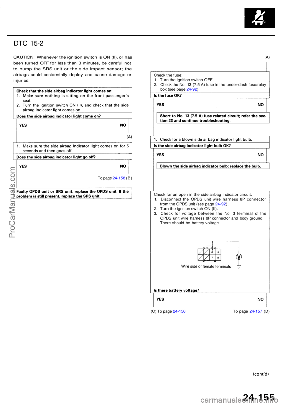
DTC 15- 2
CAUTION : Wheneve r th e ignitio n switc h is O N (II) , o r ha s
bee n turne d OF F fo r les s tha n 3 minutes , b e carefu l no t
to bum p th e SR S uni t o r th e sid e impac t sensor ; th e
airbag s coul d accidentall y deplo y an d caus e damag e o r
injuries .
Check th e fuse :1. Tur n th e ignitio n switc h OFF .2. Chec k th e No . 1 3 (7. 5 A ) fus e in th e under-das h fuse/rela y
bo x (se e pag e 24-92 ).
T o pag e 24-15 8 (B )
(C) T o pag e 24-15 6 T o pag e 24-15 7 (D )
Chec
k fo r a n ope n in th e sid e airba g indicato r circuit :
1 . Disconnec t th e OPD S uni t wir e harnes s 8 P connecto r
fro m th e OPD S uni t (se e pag e 24-92 ).
2 . Tur n th e ignitio n switc h O N (II) .3. Chec k fo r voltag e betwee n th e No . 3 termina l o f th e
OPD S uni t wir e harnes s 8 P connecto r an d bod y ground .
Ther e shoul d b e batter y voltage .
ProCarManuals.com
Page 1927 of 1954
Troubleshooting - '9 9 - 0 1 Model s
DTC 15- 2 (cont'd )
(C) Fro m pag e 24-15 5
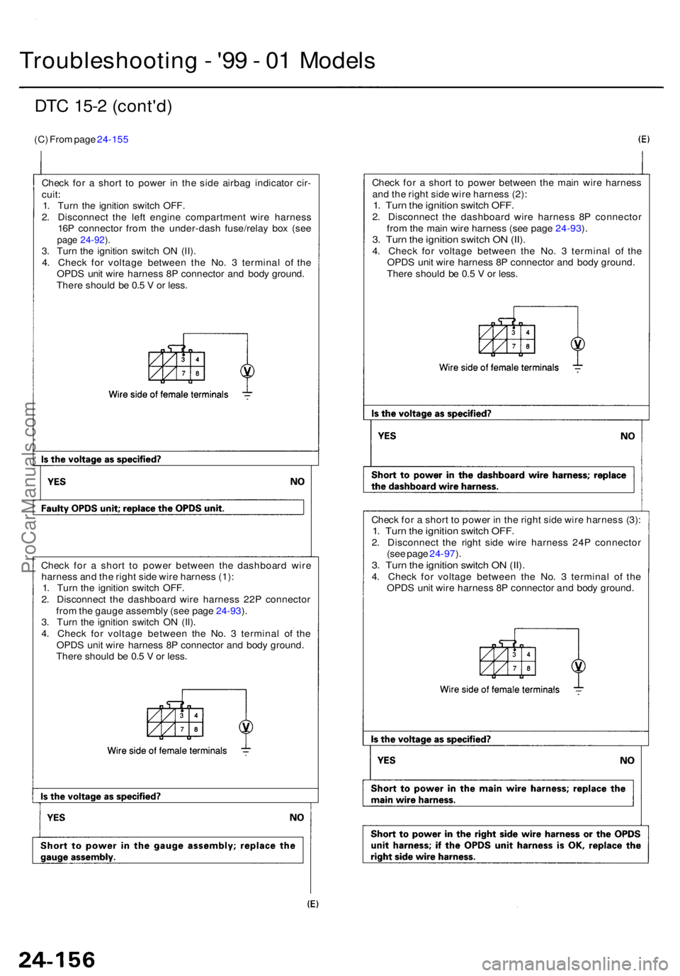
Chec k fo r a shor t t o powe r i n th e sid e airba g indicato r cir -
cuit :1. Tur n th e ignitio n switc h OFF .
2 . Disconnec t th e lef t engin e compartmen t wir e harnes s
16 P connecto r fro m th e under-das h fuse/rela y bo x (se e
page 24-92 ).3 . Tur n th e ignitio n switc h O N (II) .
4 . Chec k fo r voltag e betwee n th e No . 3 termina l o f th e
OPD S uni t wir e harnes s 8 P connecto r an d bod y ground .
Ther e shoul d b e 0. 5 V or less . Chec
k fo r a shor t t o powe r betwee n th e mai n wir e harnes s
an d th e righ t sid e wir e harnes s (2) :
1. Tur n th e ignitio n switc h OFF .2. Disconnec t th e dashboar d wir e harnes s 8 P connecto r
fro m th e mai n wir e harnes s (se e pag e 24-93 ).
3 . Tur n th e ignitio n switc h O N (II) .4. Chec k fo r voltag e betwee n th e No . 3 termina l o f th e
OPD S uni t wir e harnes s 8 P connecto r an d bod y ground .
Ther e shoul d b e 0. 5 V or less .
Chec k fo r a shor t t o powe r i n th e righ t sid e wir e harnes s (3) :
1. Tur n th e ignitio n switc h OFF .2. Disconnec t th e righ t sid e wir e harnes s 24 P connecto r
(se e pag e 24-97 ).
3 . Tur n th e ignitio n switc h O N (II) .4. Chec k fo r voltag e betwee n th e No . 3 termina l o f th e
OPD S uni t wir e harnes s 8 P connecto r an d bod y ground .
Chec
k fo r a shor t t o powe r betwee n th e dashboar d wir e
harnes s an d th e righ t sid e wir e harnes s (1) :
1 . Tur n th e ignitio n switc h OFF .
2 . Disconnec t th e dashboar d wir e harnes s 22 P connecto r
fro m th e gaug e assembl y (se e pag e 24-93 ).
3 . Tur n th e ignitio n switc h O N (II) .
4 . Chec k fo r voltag e betwee n th e No . 3 termina l o f th e
OPD S uni t wir e harnes s 8 P connecto r an d bod y ground .
Ther e shoul d b e 0. 5 V or less .
ProCarManuals.com
Page 1928 of 1954
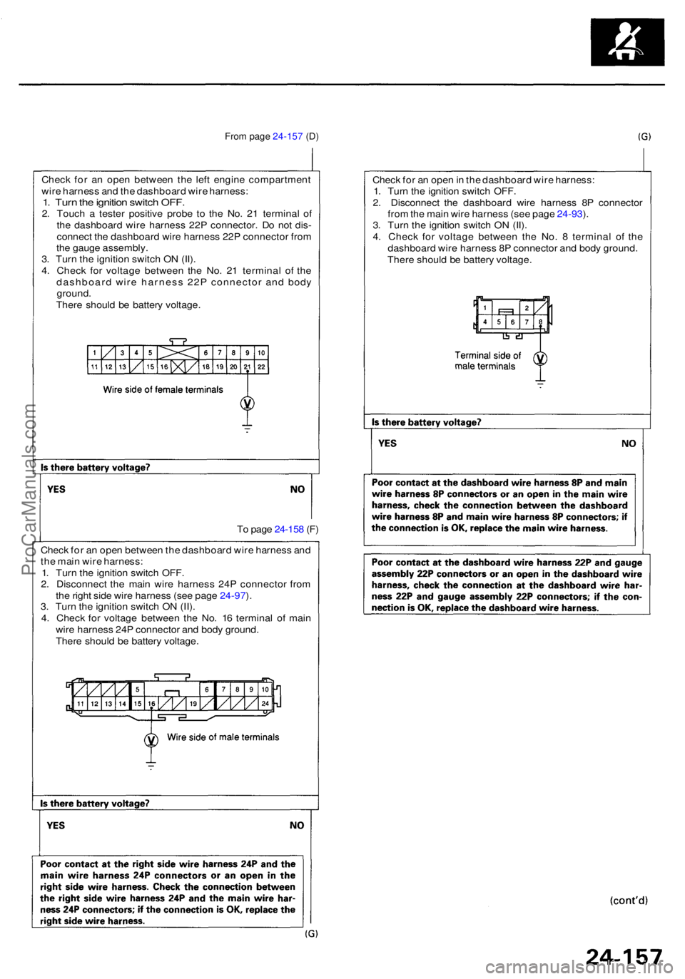
Check fo r a n ope n betwee n th e dashboar d wir e harnes s an d
th e mai n wir e harness :
1 . Tur n th e ignitio n switc h OFF .
2 . Disconnec t th e mai n wir e harnes s 24 P connecto r fro m
th e righ t sid e wir e harnes s (se e pag e 24-97 ).
3 . Tur n th e ignitio n switc h O N (II) .
4 . Chec k fo r voltag e betwee n th e No . 1 6 termina l o f mai n
wir e harnes s 24 P connecto r an d bod y ground .
Ther e shoul d b e batter y voltage . T
o pag e 24-15 8 (F ) Chec
k fo r a n ope n in th e dashboar d wir e harness :
1 . Tur n th e ignitio n switc h OFF .
2 . Disconnec t th e dashboar d wir e harnes s 8 P connecto r
fro m th e mai n wir e harnes s (se e pag e 24-93 ).
3 . Tur n th e ignitio n switc h O N (II) .
4 . Chec k fo r voltag e betwee n th e No . 8 termina l o f th e
dashboar d wir e harnes s 8 P connecto r an d bod y ground .
Ther e shoul d b e batter y voltage .
From pag e 24-15 7 (D )
Chec k fo r a n ope n betwee n th e lef t engin e compartmen t
wir e harnes s an d th e dashboar d wir e harness :
1. Tur n th e ignitio n switc h OFF .2. Touc h a teste r positiv e prob e t o th e No . 2 1 termina l o f
th e dashboar d wir e harnes s 22 P connector . D o no t dis -
connec t th e dashboar d wir e harnes s 22 P connecto r fro m
th e gaug e assembly .
3 . Tur n th e ignitio n switc h O N (II) .
4 . Chec k fo r voltag e betwee n th e No . 2 1 termina l o f th e
dashboar d wir e harnes s 22 P connecto r an d bod y
ground .
Ther e shoul d b e batter y voltage .
ProCarManuals.com
Page 1929 of 1954
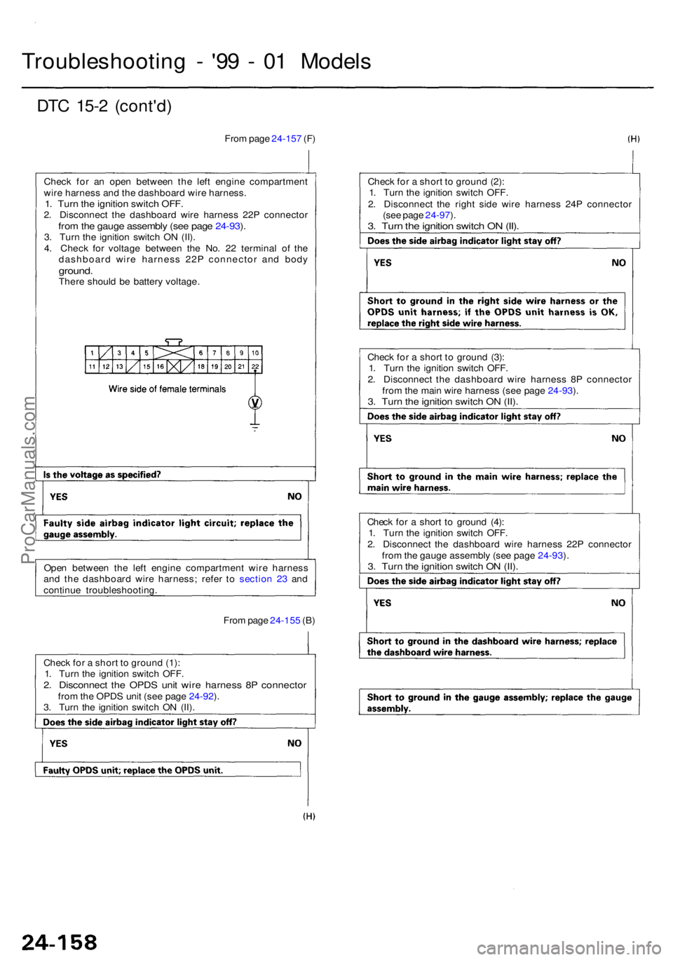
DTC 15- 2 (cont'd )
Troubleshootin g - '9 9 - 0 1 Model s
From pag e 24-15 7 (F )
Chec k fo r a n ope n betwee n th e lef t engin e compartmen t
wir e harnes s an d th e dashboar d wir e harness .
1. Tur n th e ignitio n switc h OFF .2. Disconnec t th e dashboar d wir e harnes s 22 P connecto rfrom th e gaug e assembl y (se e pag e 24-93 ).3 . Tur n th e ignitio n switc h O N (II) .
4 . Chec k fo r voltag e betwee n th e No . 2 2 termina l o f th e
dashboar d wir e harnes s 22 P connecto r an d bod y
ground .There shoul d b e batter y voltage . Chec
k fo r a shor t t o groun d (2) :
1 . Tur n th e ignitio n switc h OFF .
2 . Disconnec t th e righ t sid e wir e harnes s 24 P connecto r
(se e pag e 24-97 ).
3 . Tur n th e ignitio n switc h O N (II) .
Chec k fo r a shor t t o groun d (3) :
1 . Tur n th e ignitio n switc h OFF .
2 . Disconnec t th e dashboar d wir e harnes s 8 P connecto r
fro m th e mai n wir e harnes s (se e pag e 24-93 ).
3 . Tur n th e ignitio n switc h O N (II) .
Chec k fo r a shor t t o groun d (4) :
1 . Tur n th e ignitio n switc h OFF .
2 . Disconnec t th e dashboar d wir e harnes s 22 P connecto r
fro m th e gaug e assembl y (se e pag e 24-93 ).
3 . Tur n th e ignitio n switc h O N (II) .
Fro m pag e 24-15 5 (B )
Ope
n betwee n th e lef t engin e compartmen t wir e harnes s
an d th e dashboar d wir e harness ; refe r t o sectio n 2 3 an d
continu e troubleshooting .
Chec k fo r a shor t t o groun d (1) :
1 . Tur n th e ignitio n switc h OFF .
2. Disconnec t th e OPD S uni t wir e harnes s 8 P connecto rfrom th e OPD S uni t (se e pag e 24-92 ).
3 . Tur n th e ignitio n switc h O N (II) .
ProCarManuals.com
Page 1930 of 1954
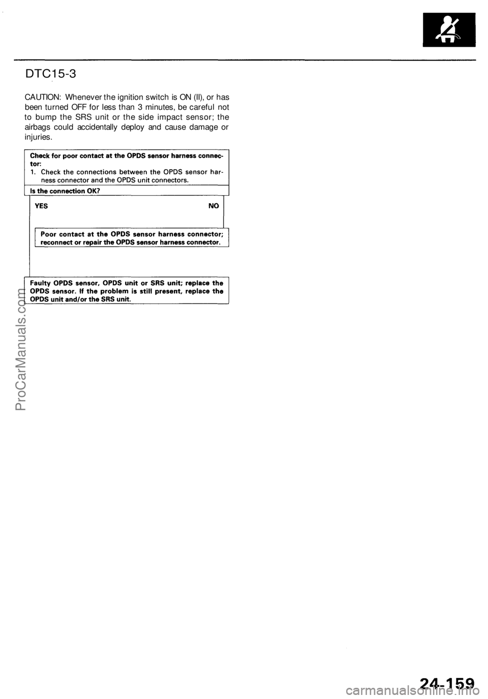
DTC15-3
CAUTION: Whenever the ignition switch is ON (II), or has
been turned OFF for less than 3 minutes, be careful not
to bump the SRS unit or the side impact sensor; the
airbags could accidentally deploy and cause damage or
injuries.ProCarManuals.com