ACURA TL 1995 Service Repair Manual
Manufacturer: ACURA, Model Year: 1995, Model line: TL, Model: ACURA TL 1995Pages: 1771, PDF Size: 62.49 MB
Page 131 of 1771
Oil Pum p
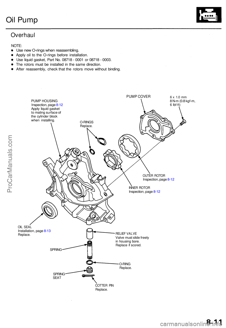
Overhau l
NOTE:
Use ne w O-ring s whe n reassembling .
Apply oi l t o th e O-ring s befor e installation .
Us e liqui d gasket , Par t No . 0871 8 - 000 1 o r 0871 8 - 0003 .
Th e rotor s mus t b e installe d in th e sam e direction .
Afte r reassembly , chec k tha t th e rotor s mov e withou t binding .
PUMP COVE R
PUMP HOUSINGInspection , pag e 8-1 2
Appl y liqui d gaske t
t o matin g surfac e o f
th e cylinde r bloc k
whe n installing .
6 x 1. 0 m m8 N- m (0. 8 kgf-m ,6 Ibf-ft )
OUTE R ROTO RInspection , pag e 8-1 2
INNE R ROTO RInspection , pag e 8-1 2
OIL SEA LInstallation , pag e 8-1 3Replace .
SPRING
SPRINGSEAT
RELIE F VALV EValve mus t slid e freel y
i n housin g bore .
Replac e i f scored .
O-RINGReplace .
COTTER PI NReplace .
O-RINGSReplace .
ProCarManuals.com
Page 132 of 1771
Oil Pum p
Removal/lnspection/lnstallatio n
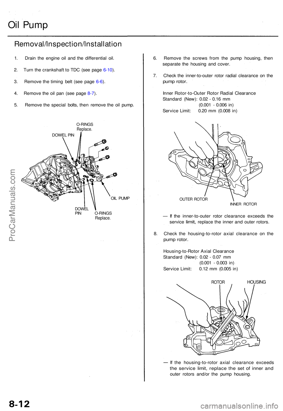
1. Drai n th e engin e oi l an d th e differentia l oil .
2 . Tur n th e crankshaf t t o TD C (se e pag e 6-10 ).
3 . Remov e th e timin g bel t (se e pag e 6-6 ).
4 . Remov e th e oi l pa n (se e pag e 8-7 ).
5 . Remov e th e specia l bolts , the n remov e th e oi l pump .
O-RING SReplace .
DOWEL PI N
OIL PUM P
DOWE LPIN O-RING SReplace.
6. Remov e th e screw s fro m th e pum p housing , the n
separat e th e housin g an d cover .
7 . Chec k th e inner-to-oute r roto r radia l clearanc e o n th e
pum p rotor .
Inner Rotor-to-Oute r Roto r Radia l Clearanc e
Standar d (New) : 0.0 2 - 0.1 6 m m
(0.00 1 - 0.00 6 in )
Servic e Limit : 0.2 0 m m (0.00 8 in )
OUTE R ROTO RINNER ROTO R
— If th e inner-to-oute r roto r clearanc e exceed s th e
servic e
limit, replac e the inne r and oute r rotors .
8 . Chec k th e housing-to-roto r axia l clearanc e o n th e
pum p rotor .
Housing-to-Roto r Axia l Clearanc e
Standar d (New) : 0.0 2 - 0.0 7 m m
(0.00 1 - 0.00 3 in )
Servic e Limit : 0.1 2 m m (0.00 5 in )
ROTO RHOUSIN G
If th e housing-to-roto r axia l clearanc e exceed s
the servic e limit , replac e th e se t of inne r an d
oute r rotor s and/o r th e pum p housing .
ProCarManuals.com
Page 133 of 1771
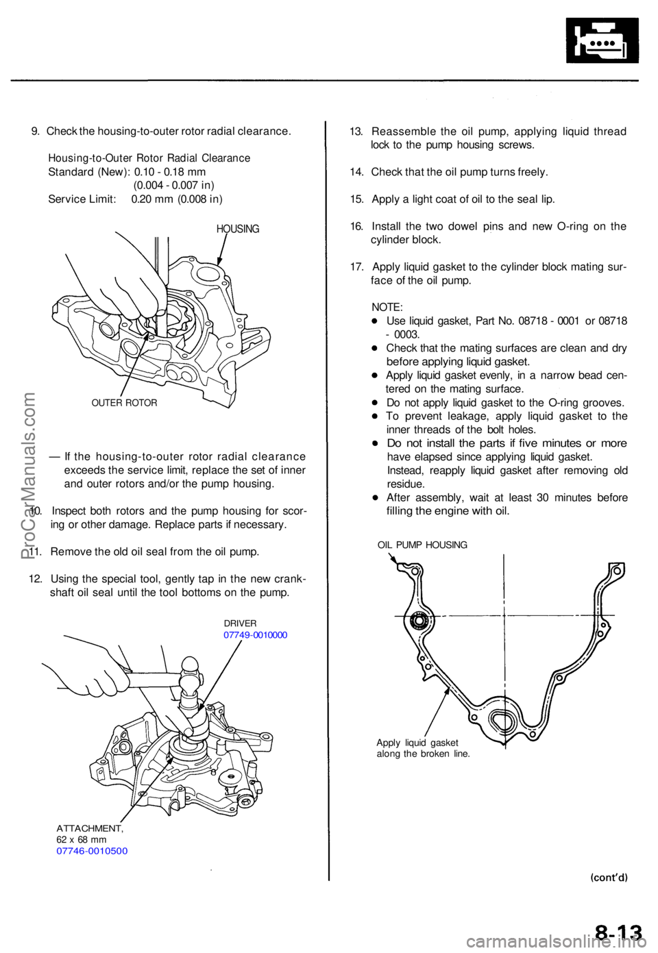
9. Chec k th e housing-to-oute r roto r radia l clearance .
Housing-to-Oute r Roto r Radia l Clearanc e
Standard (New) : 0.1 0 - 0.1 8 m m
(0.00 4 - 0.00 7 in )
Servic e Limit : 0.2 0 m m (0.00 8 in )
HOUSIN G
OUTER ROTO R
— If th e housing-to-oute r roto r radia l clearanc e
exceed s th e servic e limit , replac e th e se t o f inne r
an d oute r rotor s and/o r th e pum p housing .
10 . Inspec t bot h rotor s an d th e pum p housin g fo r scor -
in g o r othe r damage . Replac e part s if necessary .
11 . Remov e th e ol d oi l sea l fro m th e oi l pump .
12 . Usin g th e specia l tool , gentl y ta p i n th e ne w crank -
shaf t oi l sea l unti l th e too l bottom s o n th e pump .
DRIVE R07749-001000 0
ATTACHMENT ,62 x 68 m m07746-001050 0
13. Reassembl e th e oi l pump , applyin g liqui d threa d
loc k t o th e pum p housin g screws .
14 . Chec k tha t th e oi l pum p turn s freely .
15 . Appl y a ligh t coa t o f oi l t o th e sea l lip .
16 . Instal l th e tw o dowe l pin s an d ne w O-rin g o n th e
cylinde r block .
17 . Appl y liqui d gaske t t o th e cylinde r bloc k matin g sur -
fac e o f th e oi l pump .
NOTE:
Use liqui d gasket , Par t No . 0871 8 - 000 1 o r 0871 8
- 0003 .
Chec k tha t th e matin g surface s ar e clea n an d dr y
befor e applyin g liqui d gasket .
Apply liqui d gaske t evenly , i n a narro w bea d cen -
tere d o n th e matin g surface .
D o no t appl y liqui d gaske t t o th e O-rin g grooves .
T o preven t leakage , appl y liqui d gaske t t o th e
inne r thread s o f th e bol t holes .
Do no t instal l th e part s i f fiv e minute s o r mor e
have elapse d sinc e applyin g liqui d gasket .
Instead , reappl y liqui d gaske t afte r removin g ol d
residue .
Afte r assembly , wai t a t leas t 3 0 minute s befor e
filling th e engin e wit h oil .
OIL PUM P HOUSIN G
Apply liqui d gaske t
alon g th e broke n line .
ProCarManuals.com
Page 134 of 1771
Oil Pum p
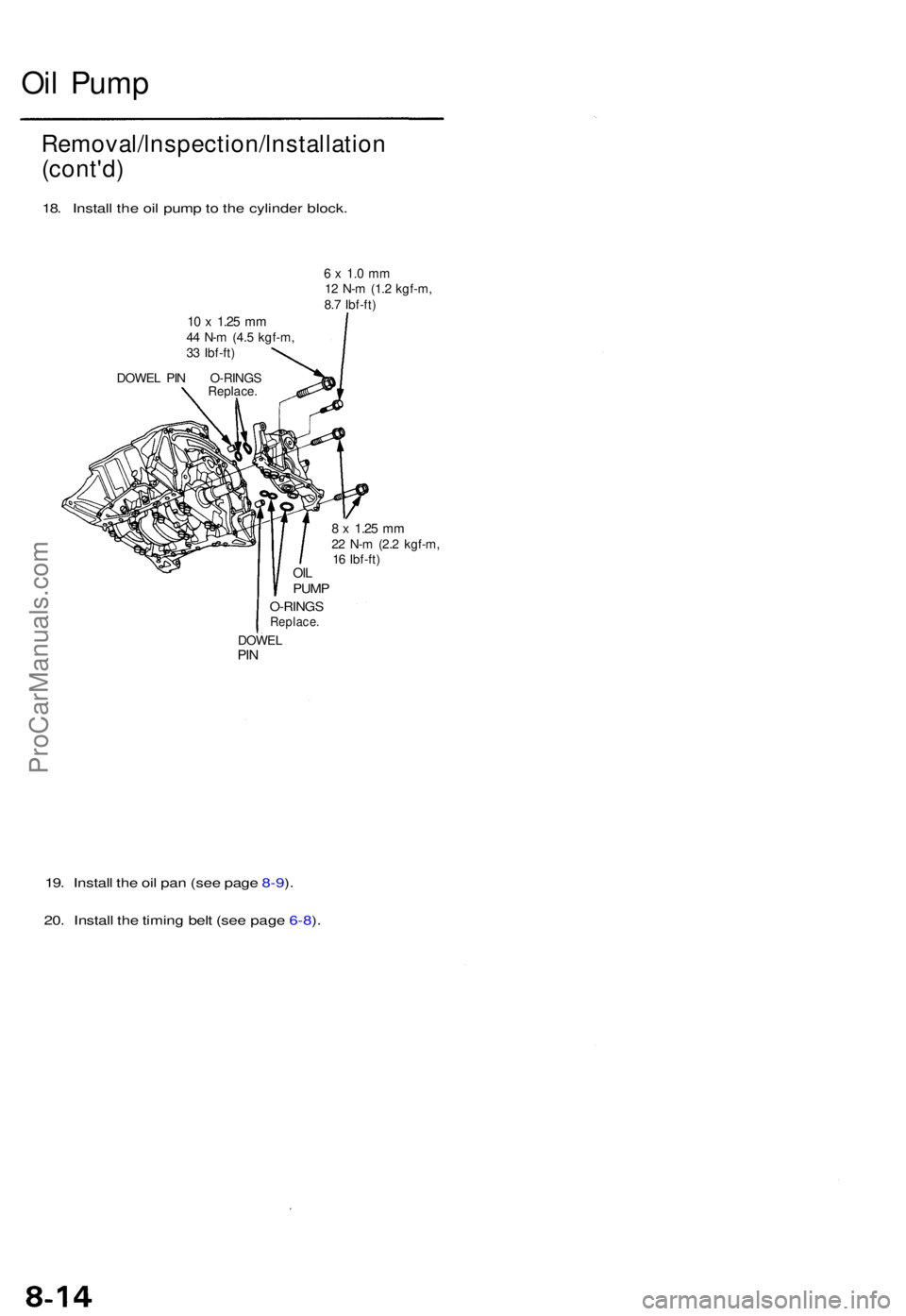
10 x 1.2 5 mm44 N- m (4. 5 kgf-m ,
3 3 Ibf-ft )
DOWE L PI N O-RING S
Replace.
6 x 1. 0 m m12 N- m (1. 2 kgf-m ,
8. 7 Ibf-ft )
OILPUM P
O-RING SReplace .
DOWELPIN
8 x 1.2 5 mm22 N- m (2. 2 kgf-m ,
1 6 Ibf-ft )
19. Instal l th e oi l pa n (se e pag e 8-9 ).
20 . Instal l th e timin g bel t (se e pag e 6-8 ).
Removal/lnspection/lnstallatio n
(cont'd )
18. Instal l th e oi l pum p to th e cylinde r block .
ProCarManuals.com
Page 135 of 1771
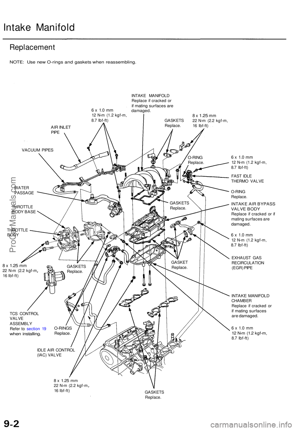
Intake Manifol d
Replacemen t
NOTE: Us e ne w O-ring s an d gasket s whe n reassembling .
6 x 1. 0 m m12 N- m (1.2 kgf-m ,
8. 7 Ibf-ft ) INTAK
E MANIFOL D
Replac e i f cracke d o r
if matin g surface s ar edamaged .
AIR INLE TPIPE
GASKET S
Replace .8 x 1.2 5 mm22 N- m (2. 2 kgf-m ,
1 6 Ibf-ft )
VACUU M PIPE S
WATE RPASSAG E
THROTTL E
BOD Y BAS E
THROTTL E
BODY
8 x 1.2 5 mm22 N- m (2. 2 kgf- m
1 6 Ibf-ft )
TC S CONTRO L
VALV E
ASSEMBL Y
Refe r t o sectio n 1 9
whe n installing .
IDLE AI R CONTRO L
(IAC ) VALV E
8 x 1.2 5 mm22 N- m (2. 2 kgf-m ,
1 6 Ibf-ft )
6 x 1. 0 m m12 N- m (1. 2 kgf-m ,
8. 7 Ibf-ft )
FAS T IDL E
THERM O VALV E
O-RIN G
Replace .
INTAKE AIR BYPASSVALVE BODYReplace i f cracke d o r i fmatin g surface s ar edamaged .
6 x 1. 0 m m12 N- m (1. 2 kgf-m ,
8. 7 Ibf-ft )
EXHAUS T GA S
RECIRCULATIO N
(EGR ) PIP E
INTAK E MANIFOL DCHAMBER
Replac e i f cracke d o r
if matin g surface sare damaged .
6 x 1. 0 m m12 N- m (1. 2 kgf-m ,8.7 Ibf-ft )
GASKET S
Replace.
O-RINGSReplace .
GASKETReplace .
GASKET
S
Replace . GASKET
S
Replace.
O-RINGReplace .
ProCarManuals.com
Page 136 of 1771
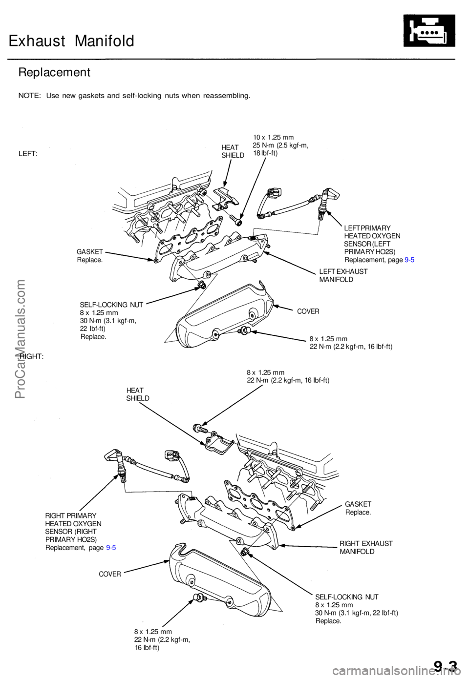
Exhaust Manifol d
Replacemen t
NOTE: Us e ne w gasket s an d self-lockin g nut s whe n reassembling .
LEFT:
10 x 1.2 5 mm25 N- m (2. 5 kgf-m ,
1 8 Ibf-ft )
GASKE TReplace .
SELF-LOCKIN G NU T8 x 1.2 5 mm30 N- m (3. 1 kgf-m ,22 Ibf-ft )Replace .
LEFT PRIMAR Y
HEATE D OXYGE N
SENSO R (LEF T
PRIMAR Y HO2S )
Replacement , pag e 9- 5
LEF T EXHAUS T
MANIFOL D
8 x 1.2 5 mm22 N- m (2. 2 kgf-m , 1 6 Ibf-ft )
RIGHT :
8 x 1.2 5 mm22 N- m (2. 2 kgf-m , 1 6 Ibf-ft )
HEATSHIEL D
RIGH T PRIMAR Y
HEATED OXYGE NSENSOR (RIGH T
PRIMAR Y HO2S )
Replacement , pag e 9- 5
COVE R
GASKE TReplace .
RIGHT EXHAUS TMANIFOLD
SELF-LOCKIN G NU T8 x 1.2 5 mm30 N- m (3. 1 kgf-m , 2 2 Ibf-ft )Replace .
8 x 1.2 5 mm22 N- m (2. 2 kgf-m ,
1 6 Ibf-ft )
COVE R
HEATSHIEL D
ProCarManuals.com
Page 137 of 1771
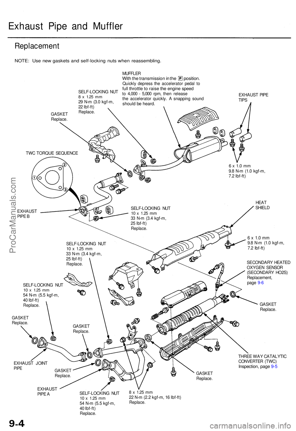
Exhaust Pip e an d Muffle r
Replacemen t
NOTE: Us e ne w gasket s an d self-lockin g nut s whe n reassembling .
GASKETReplace . MUFFLE
R
With th e transmissio n in th e position .Quickly depres s th e accelerato r peda l t oful l throttl e to rais e th e engin e spee dto 4,00 0 - 5,00 0 rpm , the n releas e
th e accelerato r quickly . A snappin g soun d
should b e heard .
EXHAUS T PIP E
TIP S
EXHAUS T
PIP E B
6 x 1. 0 m m9.8 N- m (1. 0 kgf-m ,
7. 2 Ibf-ft )
HEAT
SHIEL D
GASKE TReplace .
6 x 1. 0 m m9.8 N- m (1. 0 kgf-m ,
7. 2 Ibf-ft )
SECONDAR Y HEATE D
OXYGE N SENSO R
(SECONDAR Y HO2S )
Replacement ,
pag e 9- 6
GASKE TReplace .
EXHAUS T JOIN T
PIPE
THRE E WA Y CATALYTI C
CONVERTE R (TWC )
Inspection , pag e 9- 5
GASKE TReplace .
EXHAUS T
PIP E A SELF-LOCKIN
G NU T
10 x 1.2 5 mm54 N- m (5. 5 kgf-m ,
4 0 Ibf-ft )
Replace .
8 x 1.2 5 mm22 N- m (2. 2 kgf-m , 1 6 Ibf-ft )Replace .
TWC TORQU E SEQUENC E
SELF-LOCKING NU T
10 x 1.2 5 mm33 N- m (3. 4 kgf-m ,
2 5 Ibf-ft )
Replace .
SELF-LOCKIN G NU T10 x 1.2 5 mm33 N- m (3. 4 kgf-m ,
2 5 Ibf-ft )
Replace .
SELF-LOCKIN G NU T10 x 1.2 5 mm54 N- m (5. 5 kgf-m ,
4 0 Ibf-ft )
Replace .
GASKETReplace .
GASKETReplace .
SELF-LOCKIN G NU T8 x 1.2 5 mm29 N- m (3. 0 kgf-m ,
2 2 Ibf-ft )
Replace .
ProCarManuals.com
Page 138 of 1771
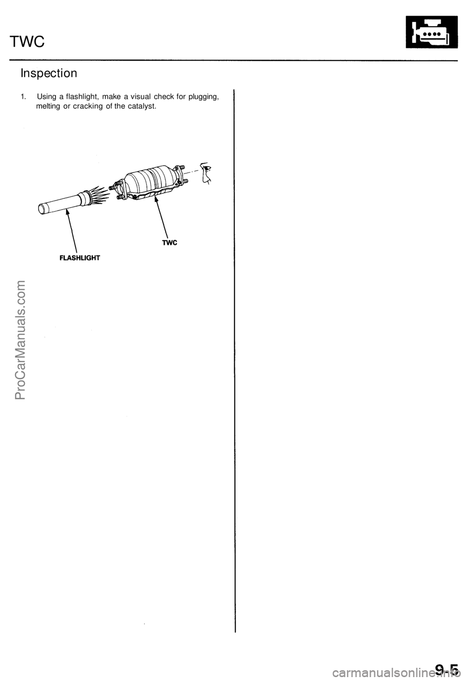
Inspection
1. Using a flashlight, make a visual check for plugging,
melting or cracking of the catalyst.
TWCProCarManuals.com
Page 139 of 1771
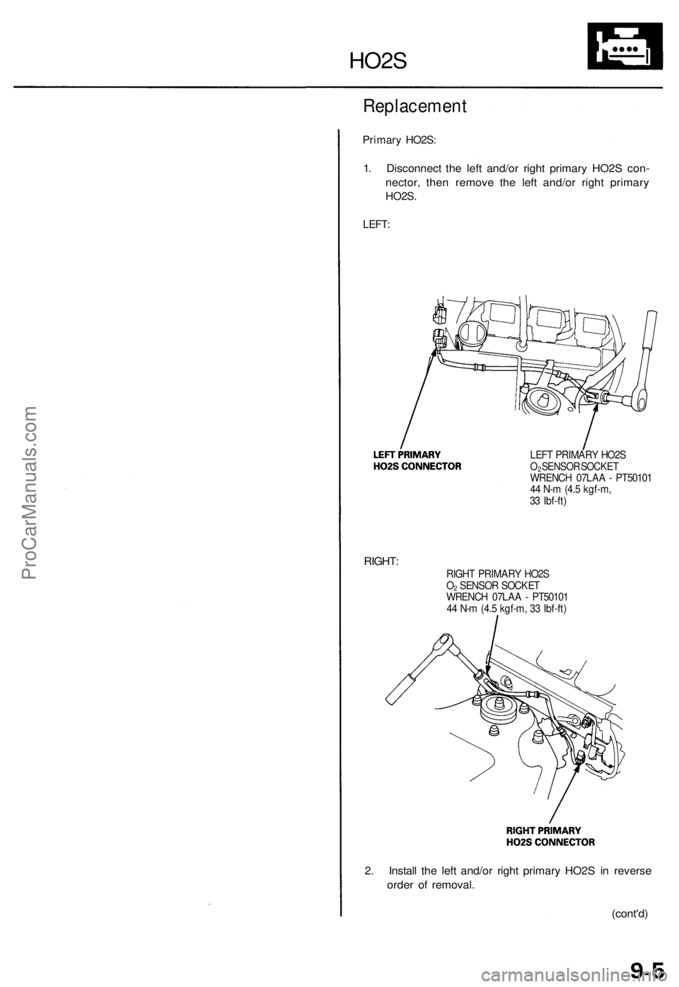
Replacement
Primary HO2S:
1. Disconnect the left and/or right primary HO2S con-
nector, then remove the left and/or right primary
HO2S.
LEFT:
HO2S
LEFT PRIMARY HO2S
O2 SENSOR SOCKET
WRENCH 07LAA - PT50101
44 N-m (4.5 kgf-m,
33 Ibf-ft)
RIGHT:
RIGHT PRIMARY HO2S
O2 SENSOR SOCKET
WRENCH 07LAA - PT50101
44 N-m (4.5 kgf-m, 33 Ibf-ft)
2. Install the left and/or right primary HO2S in reverse
order of removal.
(cont'd)ProCarManuals.com
Page 140 of 1771
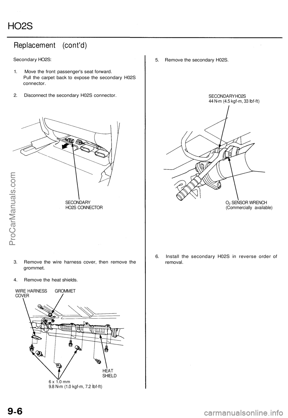
HO2S
Replacement (cont'd)
Secondary HO2S:
1. Move the front passenger's seat forward.
Pull the carpet back to expose the secondary H02S
connector.
2. Disconnect the secondary H02S connector.
SECONDARY
HO2S CONNECTOR
3. Remove the wire harness cover, then remove the
grommet.
4. Remove the heat shields.
WIRE HARNESS GROMMET
COVER
HEAT
SHIELD
6 x 1.0 mm
9.8 N-m (1.0 kgf-m, 7.2 Ibf-ft)
5. Remove the secondary H02S.
SECONDARY HO2S
44 N-m (4.5 kgf-m, 33 Ibf-ft)
O2 SENSOR WRENCH
(Commercially available)
6. Install the secondary H02S in reverse order of
removal.ProCarManuals.com