ACURA TL 1995 Service Repair Manual
Manufacturer: ACURA, Model Year: 1995, Model line: TL, Model: ACURA TL 1995Pages: 1771, PDF Size: 62.49 MB
Page 141 of 1771
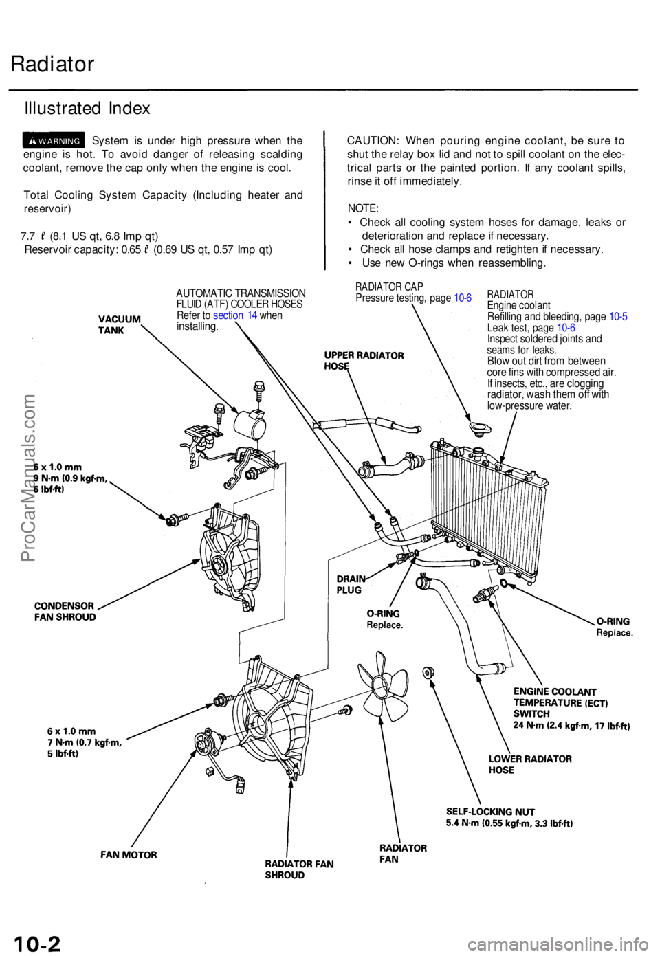
Radiator
Illustrate d Inde x
Syste m is unde r hig h pressur e whe n th e
engin e i s hot . T o avoi d dange r o f releasin g scaldin g
coolant , remov e th e ca p onl y whe n th e engin e is cool .
Tota l Coolin g Syste m Capacit y (Includin g heate r an d
reservoir )
7.7 (8. 1 US qt , 6. 8 Im p qt )
Reservoi r capacity : 0.6 5 (0.6 9 U S qt , 0.5 7 Im p qt ) CAUTION
: Whe n pourin g engin e coolant , b e sur e t o
shu t th e rela y bo x li d an d no t t o spil l coolan t o n th e elec -
trica l part s o r th e painte d portion . I f an y coolan t spills ,
rins e it of f immediately .
NOTE:
• Chec k al l coolin g syste m hose s fo r damage , leak s o r
deterioratio n an d replac e if necessary .
• Chec k al l hos e clamp s an d retighte n if necessary .
• Us e ne w O-ring s whe n reassembling .
RADIATOR CA PPressur e testing , pag e 10- 6RADIATO REngine coolan t
Refillin g an d bleeding , pag e 10- 5
Leak test , pag e 10- 6Inspec t soldere d joint s an dseam s fo r leaks .Blow ou t dir t fro m betwee ncore fin s wit h compresse d air .If insects , etc. , ar e cloggin gradiator , was h the m of f wit hlow-pressur e water .
AUTOMATI C TRANSMISSIO NFLUID (ATF ) COOLE R HOSE SRefer t o sectio n 1 4 whe ninstalling .
ProCarManuals.com
Page 142 of 1771
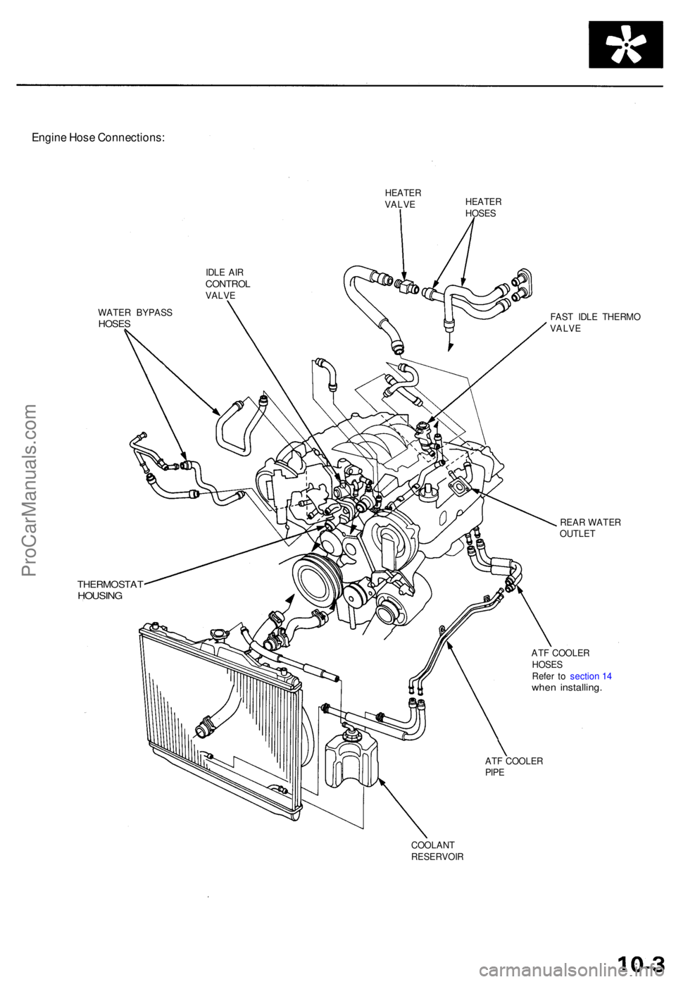
Engine Hos e Connections :
HEATERVALVEHEATE RHOSES
IDL E AI R
CONTRO LVALVE
WATE R BYPAS S
HOSES
THERMOSTA THOUSING
FAST IDL E THERM O
VALV E
REA R WATE R
OUTLE T
AT F COOLE R
HOSE S
Refe r t o sectio n 1 4
whe n installing .
ATF COOLE R
PIP E
COOLAN T
RESERVOI R
ProCarManuals.com
Page 143 of 1771
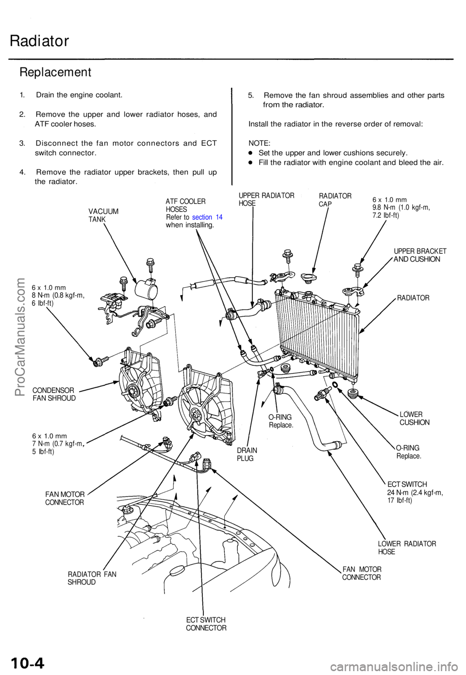
Radiator
5. Remov e th e fa n shrou d assemblie s an d othe r part s
from th e radiator .
Install th e radiato r i n th e revers e orde r o f removal :
NOTE:
Set th e uppe r an d lowe r cushion s securely .
Fil l th e radiato r wit h engin e coolan t an d blee d th e air .
VACUU MTANK
6 x 1. 0 m m8 N- m (0. 8 kgf-m ,6 Ibf-ft )
CONDENSO RFAN SHROU D
6 x 1. 0 m m7 N- m (0. 7 kgf-m ,
5 Ibf-ft )
FAN MOTO RCONNECTO R
RADIATO R FA N
SHROU D
ATF COOLE R
HOSE S
Refe r t o sectio n 1 4
whe n installing .
UPPER RADIATO R
HOS E RADIATO
RCAP6 x 1. 0 m m9.8 N- m (1. 0 kgf-m ,
7. 2 Ibf-ft )
UPPE R BRACKE T
AND CUSHIO N
RADIATO R
LOWE R
CUSHIO N
O-RINGReplace .
ECT SWITC H24 N- m (2. 4 kgf-m ,17 Ibf-ft )
LOWE R RADIATO R
HOS E
FA N MOTO R
CONNECTO R
ECT SWITC HCONNECTO R
DRAINPLUG
O-RIN GReplace .
Replacemen t
1. Drai n th e engin e coolant .
2 . Remov e th e uppe r an d lowe r radiato r hoses , an d
AT F coole r hoses .
3 . Disconnec t th e fa n moto r connector s an d EC T
switc h connector .
4 . Remov e th e radiato r uppe r brackets , the n pul l u p
th e radiator .
ProCarManuals.com
Page 144 of 1771
Engine Coolan t Refillin g an d Bleedin g
CAUTION : Whe n pourin g engin e coolant , b e sur e t o
shu t th e rela y bo x li d an d no t t o le t coolan t spil l o n th e
electrica l part s o r th e paint . I f an y coolan t spills , rins e it
of f immediately .
NOTE:
Perfor m thi s procedur e whe n th e engin e is cool .
Befor e replacin g th e coolant , tur n th e ignitio n O N (II) ,
slowl y tur n th e climat e contro l temperatur e kno b t o
90 ° an d tur n of f th e ignition . Thi s wil l allo w th e
coolan t i n th e heate r t o drai n ou t wit h th e res t o f th e
system .
1 . Mak e sur e yo u hav e th e anti-thef t cod e fo r th e radio ,
the n writ e dow n th e frequencie s fo r th e radio' s pre -
se t buttons .
2 . Disconnec t th e batter y negativ e termina l first , the n
th e positiv e terminal , the n remov e th e batter y an d
batter y bas e (se e pag e 5-4 ).
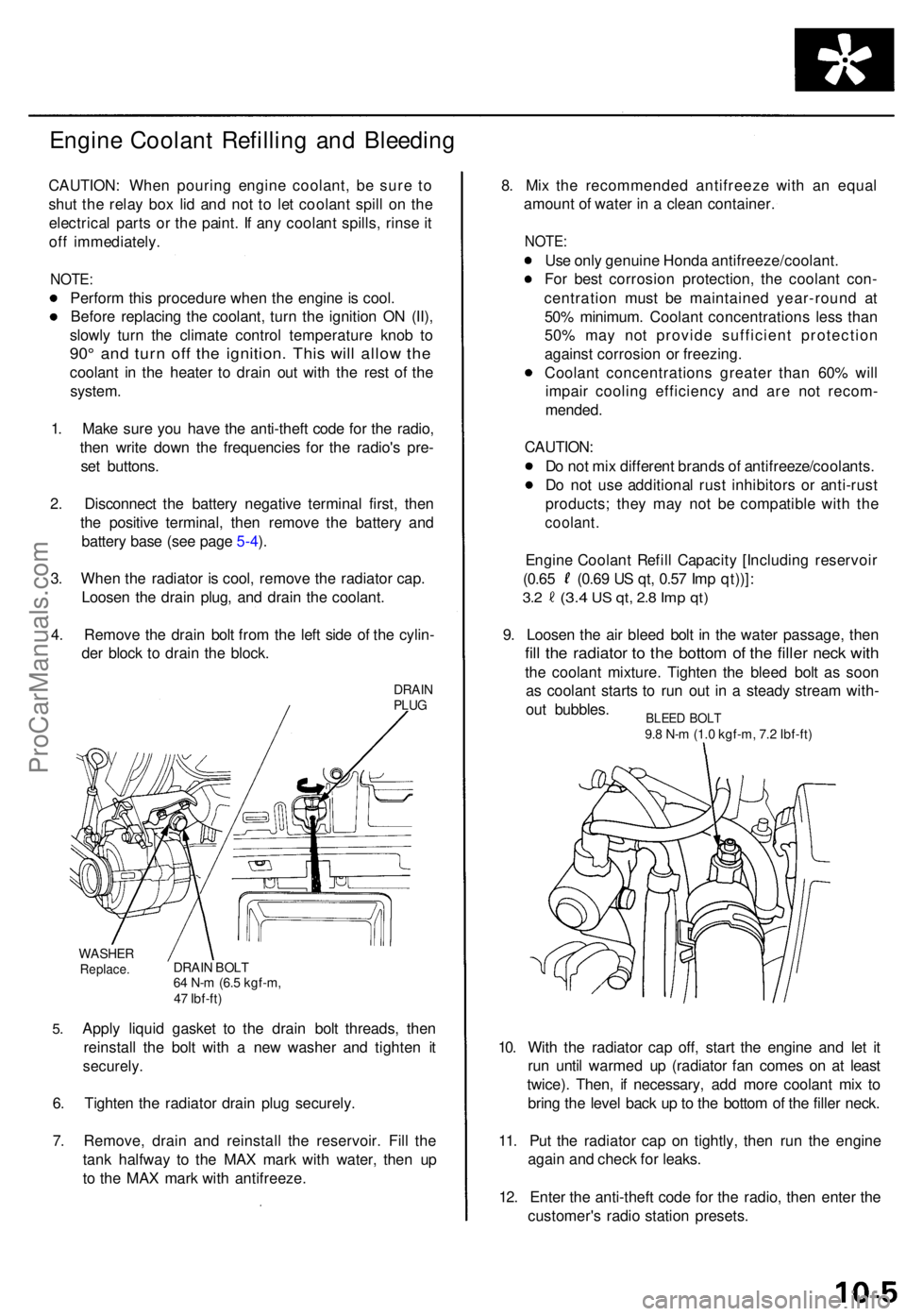
3 . Whe n th e radiato r i s cool , remov e th e radiato r cap .
Loose n th e drai n plug , an d drai n th e coolant .
4 . Remov e th e drai n bol t fro m th e lef t sid e o f th e cylin -
de r bloc k t o drai n th e block .
DRAINPLUG
5.
WASHE RReplace .DRAIN BOL T64 N- m (6. 5 kgf-m ,
4 7 Ibf-ft )
Apply liqui d gaske t t o th e drai n bol t threads , the n
reinstal l th e bol t wit h a ne w washe r an d tighte n i t
securely .
6. Tighte n th e radiato r drai n plu g securely .
7 . Remove , drai n an d reinstal l th e reservoir . Fil l th e
tan k halfwa y t o th e MA X mar k wit h water , the n u p
t o th e MA X mar k wit h antifreeze . 8
. Mi x th e recommende d antifreez e wit h a n equa l
amoun t o f wate r i n a clea n container .
NOTE:
Use onl y genuin e Hond a antifreeze/coolant .
Fo r bes t corrosio n protection , th e coolan t con -
centratio n mus t b e maintaine d year-roun d a t
50 % minimum . Coolan t concentration s les s tha n
50 % ma y no t provid e sufficien t protectio n
agains t corrosio n o r freezing .
Coolan t concentration s greate r tha n 60 % wil l
impai r coolin g efficienc y an d ar e no t recom -
mended .
CAUTION :
D o no t mi x differen t brand s o f antifreeze/coolants .
D o no t us e additiona l rus t inhibitor s o r anti-rus t
products ; the y ma y no t b e compatibl e wit h th e
coolant .
Engine Coolan t Refil l Capacit y [Includin g reservoi r
(0.65 (0.6 9 U S qt , 0.5 7 Im p qt))] :
3.2 (3. 4 US qt , 2. 8 Im p qt )
9. Loose n th e ai r blee d bol t i n th e wate r passage , the n
fill th e radiato r t o th e botto m o f th e fille r nec k wit h
the coolan t mixture . Tighte n th e blee d bol t a s soo n
a s coolan t start s t o ru n ou t i n a stead y strea m with -
ou t bubbles .
10 . Wit h th e radiato r ca p off , star t th e engin e an d le t i t
ru n unti l warme d u p (radiato r fa n come s o n a t leas t
twice) . Then , i f necessary , ad d mor e coolan t mi x t o
brin g th e leve l bac k u p to th e botto m o f th e fille r neck .
11 . Pu t th e radiato r cap on tightly , the n ru n th e engin e
agai n an d chec k fo r leaks .
12 . Ente r th e anti-thef t cod e fo r th e radio , the n ente r th e
customer' s radi o statio n presets .
BLEED BOL T9.8 N- m (1. 0 kgf-m , 7. 2 Ibf-ft )
ProCarManuals.com
Page 145 of 1771
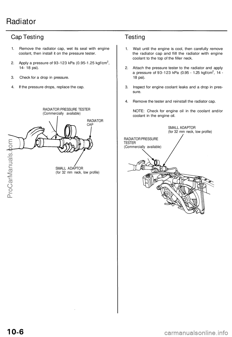
Radiator
Cap Testing
1. Remove the radiator cap, wet its seal with engine
coolant, then install it on the pressure tester.
2. Apply a pressure of 93-123 kPa (0.95-1.25 kgf/cm2,
14- 18
psi).
3. Check for a drop in pressure.
4. If the pressure drops, replace the cap.
RADIATOR PRESSURE TESTER
(Commercially available)
Testing
RADIATOR
CAP
SMALL ADAPTOR
(for 32 mm neck, low profile)
1. Wait until the engine is cool, then carefully remove
the
radiator
cap and
fill
the
radiator
with
engine
coolant to the top of the filler neck.
2. Attach the pressure tester to the radiator and apply
a pressure of 93-123 kPa (0.95 - 1.25 kgf/cm2, 14 -
18
psi).
3. Inspect for engine coolant leaks and a drop in pres-
sure.
4. Remove the tester and reinstall the radiator cap.
NOTE: Check for engine oil in the coolant and/or
coolant in the engine oil.
SMALL ADAPTOR
(for 32 mm neck, low profile)
RADIATOR PRESSURE
TESTER
(Commercially available)ProCarManuals.com
Page 146 of 1771
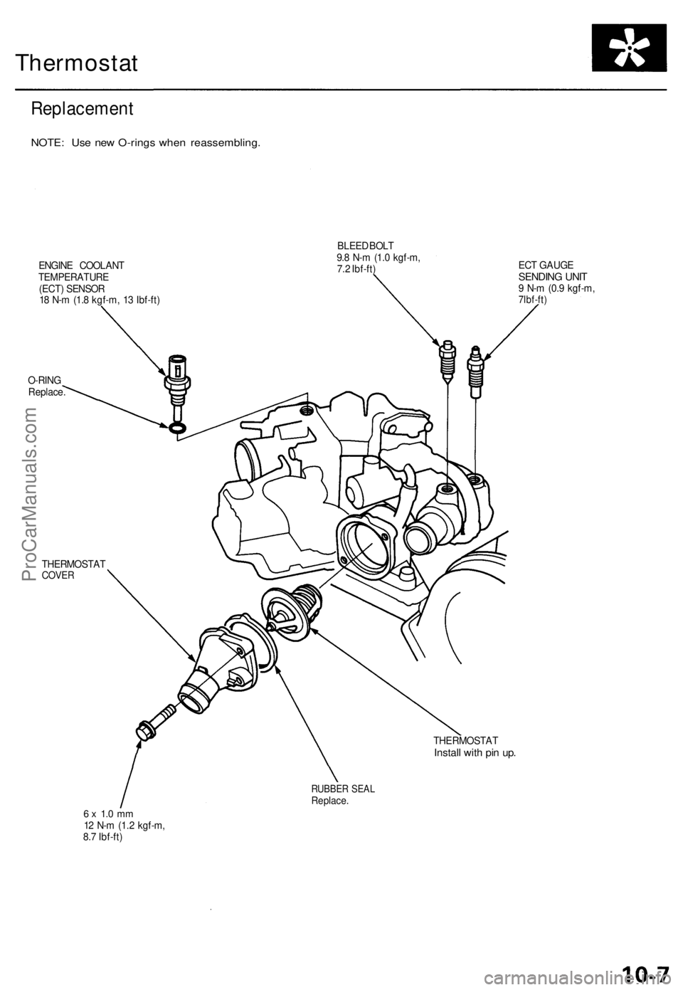
Thermostat
Replacement
NOTE: Use new O-rings when reassembling.
ENGINE COOLANT
TEMPERATURE
(ECT) SENSOR
18 N-m (1.8 kgf-m, 13 Ibf-ft)
BLEED BOLT
9.8 N-m (1.0 kgf-m,
7.2 Ibf-ft)
O-RING
Replace.
ECT GAUGE
SENDING UNIT
9 N-m (0.9 kgf-m,
7lbf-ft)
THERMOSTAT
COVER
THERMOSTAT
Install with pin up.
RUBBER SEAL
Replace.
6 x 1.0 mm
12 N-m (1.2 kgf-m,
8.7 Ibf-ft)ProCarManuals.com
Page 147 of 1771
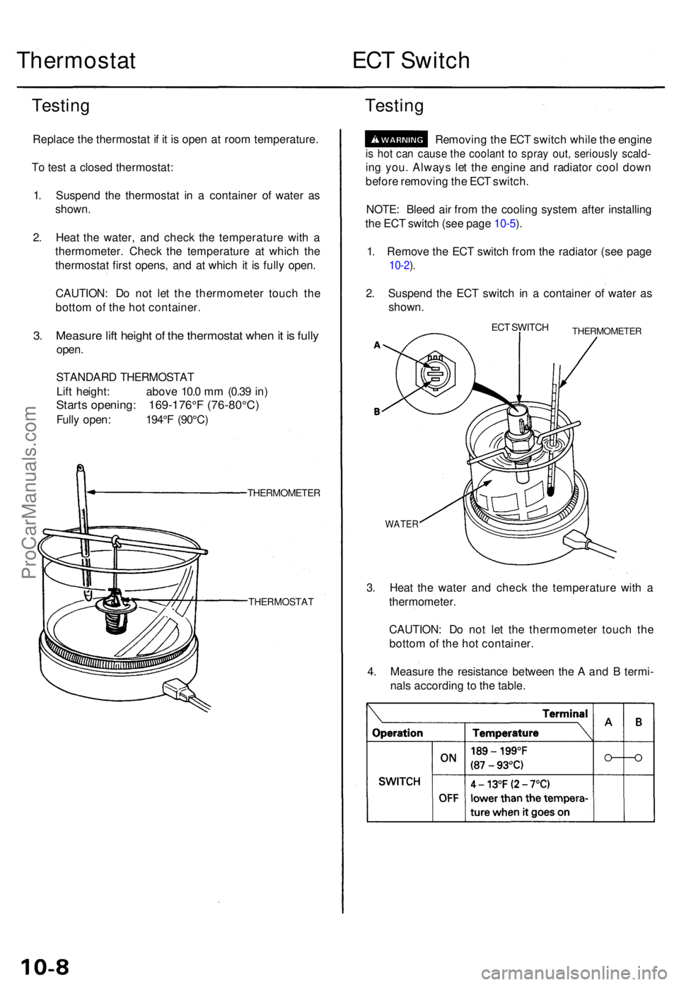
Thermostat ECT Switc h
Testin g
Replac e th e thermosta t i f i t i s ope n a t roo m temperature .
T o tes t a close d thermostat :
1 . Suspen d th e thermosta t i n a containe r o f wate r a s
shown .
2 . Hea t th e water , an d chec k th e temperatur e wit h a
thermometer . Chec k th e temperatur e a t whic h th e
thermosta t firs t opens , an d a t whic h i t i s full y open .
CAUTION : D o no t le t th e thermomete r touc h th e
botto m o f th e ho t container .
3. Measur e lif t heigh t o f th e thermosta t whe n it i s full y
open .
STANDAR D THERMOSTA T
Lif t height : abov e 10. 0 m m (0.3 9 in )
Start s opening : 169-176° F (76-80°C )
Fully open : 194° F (90°C )
THERMOMETE R
THERMOSTAT
Testing
Removin g th e EC T switc h whil e th e engin e
is ho t ca n caus e th e coolan t t o spra y out , seriousl y scald -
ing you . Alway s le t th e engin e an d radiato r coo l dow n
befor e removin g th e EC T switch .
NOTE : Blee d ai r fro m th e coolin g syste m afte r installin g
th e EC T switc h (se e pag e 10-5 ).
1 . Remov e th e EC T switc h fro m th e radiato r (se e pag e
10-2).
2 . Suspen d th e EC T switc h i n a containe r o f wate r a s
shown .
ECT SWITC HTHERMOMETE R
WATER
3. Hea t th e wate r an d chec k th e temperatur e wit h a
thermometer .
CAUTION : D o no t le t th e thermomete r touc h th e
botto m of th e ho t container .
4 . Measur e th e resistanc e betwee n th e A an d B termi -
nal s accordin g t o th e table .
ProCarManuals.com
Page 148 of 1771
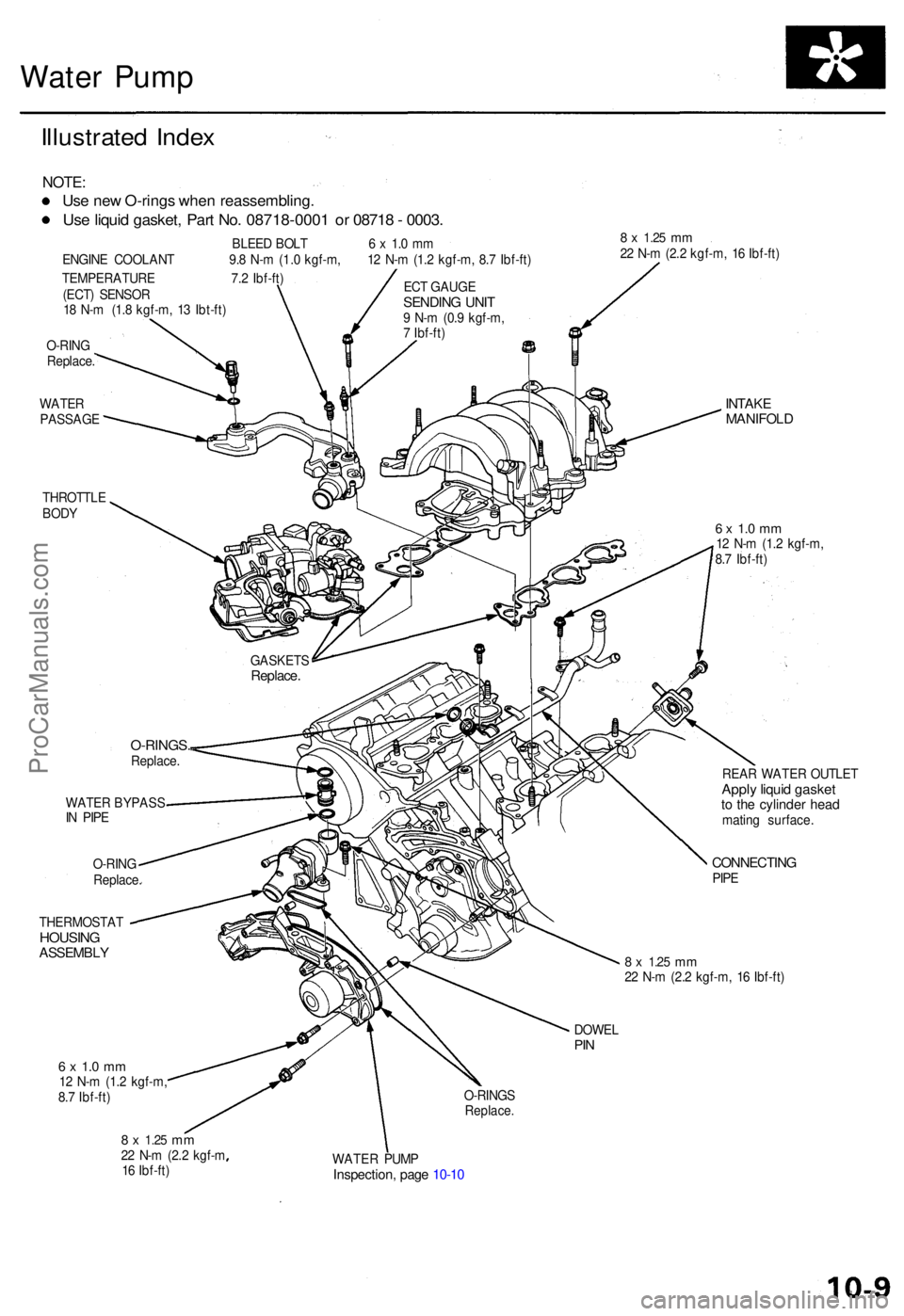
Water Pum p
Illustrate d Inde x
NOTE :
Use ne w O-ring s whe n reassembling .
Use liqui d gasket , Par t No . 08718-000 1 o r 0871 8 - 0003 .
BLEE D BOL T 6 x 1. 0 m m
ENGIN E COOLAN T 9. 8 N- m (1. 0 kgf-m , 1 2 N- m (1. 2 kgf-m , 8. 7 Ibf-ft )
TEMPERATUR E 7. 2 Ibf-ft )
(ECT ) SENSO R
1 8 N- m (1. 8 kgf-m , 1 3 Ibt-ft )
O-RIN G
Replace .
WATE R
PASSAG E
THROTTL E
BOD Y8 x 1.2 5 mm22 N- m (2. 2 kgf-m , 1 6 Ibf-ft )
WATE R BYPAS S
I N PIP E
O-RIN G
Replace .
THERMOSTA T
HOUSINGASSEMBL Y
INTAKEMANIFOL D
6 x 1. 0 m m12 N- m (1. 2 kgf-m ,
8. 7 Ibf-ft )
REA R WATE R OUTLE T
Apply liqui d gaske tto th e cylinde r hea dmatin g surface .
CONNECTIN GPIPE
8 x 1.2 5 mm22 N- m (2. 2 kgf-m , 1 6 Ibf-ft )
DOWE L
PIN
6 x 1. 0 m m12 N- m (1. 2 kgf-m ,
8. 7 Ibf-ft ) O-RING
S
Replace .
8 x 1.2 5 mm22 N- m (2. 2 kgf- m
1 6 Ibf-ft ) WATE
R PUM P
Inspection , pag e 10-1 0
GASKET SReplace.
O-RINGS .Replace. EC
T GAUG E
SENDIN G UNI T9 N- m (0. 9 kgf-m ,
7 Ibf-ft )
ProCarManuals.com
Page 149 of 1771
Water Pum p
Inspectio n
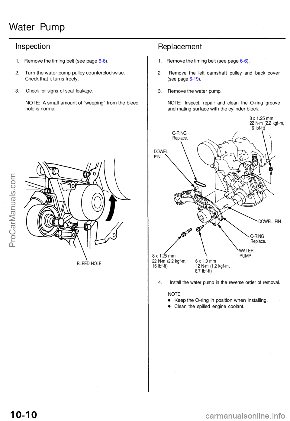
1. Remov e th e timin g bel t (se e pag e 6-6 ).
2 . Tur n th e wate r pum p pulle y counterclockwise .
Check tha t i t turn s freely .
3. Chec k fo r sign s o f sea l leakage .
NOTE: A smal l amoun t o f "weeping " fro m th e blee d
hole is normal .
BLEED HOL E
Replacemen t
1. Remov e th e timin g bel t (se e pag e 6-6 ).
2 . Remov e th e lef t camshaf t pulle y an d bac k cove r
(se e pag e 6-19 ).
3 . Remov e th e wate r pump .
NOTE: Inspect , repai r an d clea n th e O-rin g groov e
and matin g surfac e wit h th e cylinde r block .
8 x 1.2 5 mm22 N- m (2. 2 kgf-m ,
1 6 Ibf-ft )
O-RIN GReplace .
DOWE L
PIN
DOWE L PI N
O-RIN G
Replace .
WATER8 x 1.2 5 m m \ PUM P22 N- m (2. 2 kgf-m , 6 x 1. 0 m m
1 6 Ibf-ft ) 1 2 N- m (1. 2 kgf-m ,
8. 7 Ibf-ft )
4. Instal l th e wate r pum p in th e revers e orde r o f removal .
NOTE :
Keep th e O-rin g in positio n whe n installing .
Clean th e spille d engin e coolant .
ProCarManuals.com
Page 150 of 1771
Special Tool s
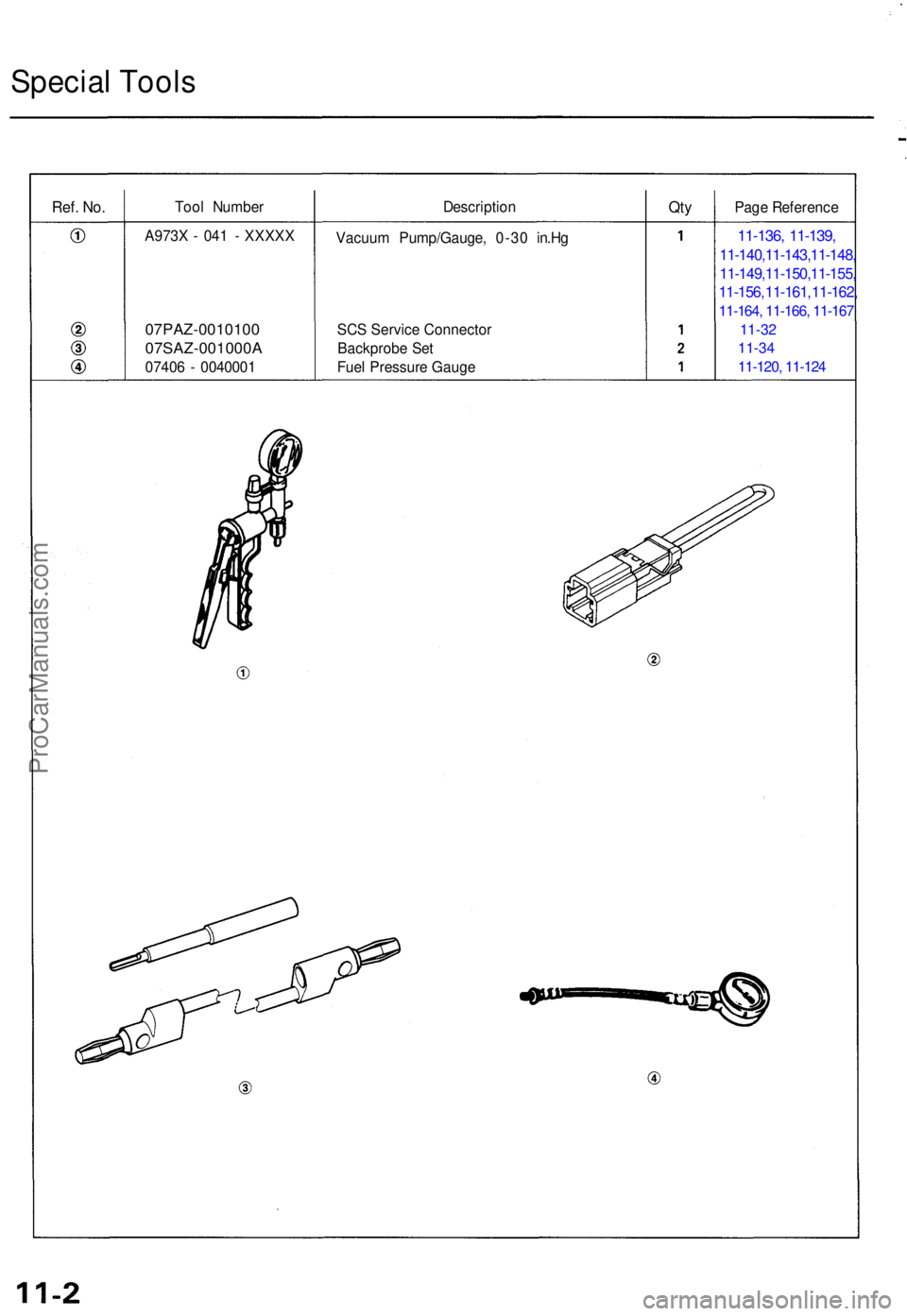
Ref. No.Too l Numbe r DescriptionQtyPag e Referenc e
A973 X - 04 1 - XXXX X
07PAZ-001010 0
07SAZ-001000 A
07406 - 004000 1 Vacuu
m Pump/Gauge , 0-3 0 in.H g
SC S Servic e Connecto r
Backprob e Se t
Fue l Pressur e Gaug e
11-136 , 11-139 ,
11-140,11-143,11-148,
11-149,11-150,11-155,
11-156, 11-161, 11-162,
11-164, 11-166, 11-167
11-32
11-34
11-120, 11-124
ProCarManuals.com