ACURA TL 1995 Service Repair Manual
Manufacturer: ACURA, Model Year: 1995, Model line: TL, Model: ACURA TL 1995Pages: 1771, PDF Size: 62.49 MB
Page 251 of 1771
Emission Control System
Exhaust Gas Recirculation (EGR) System
Description
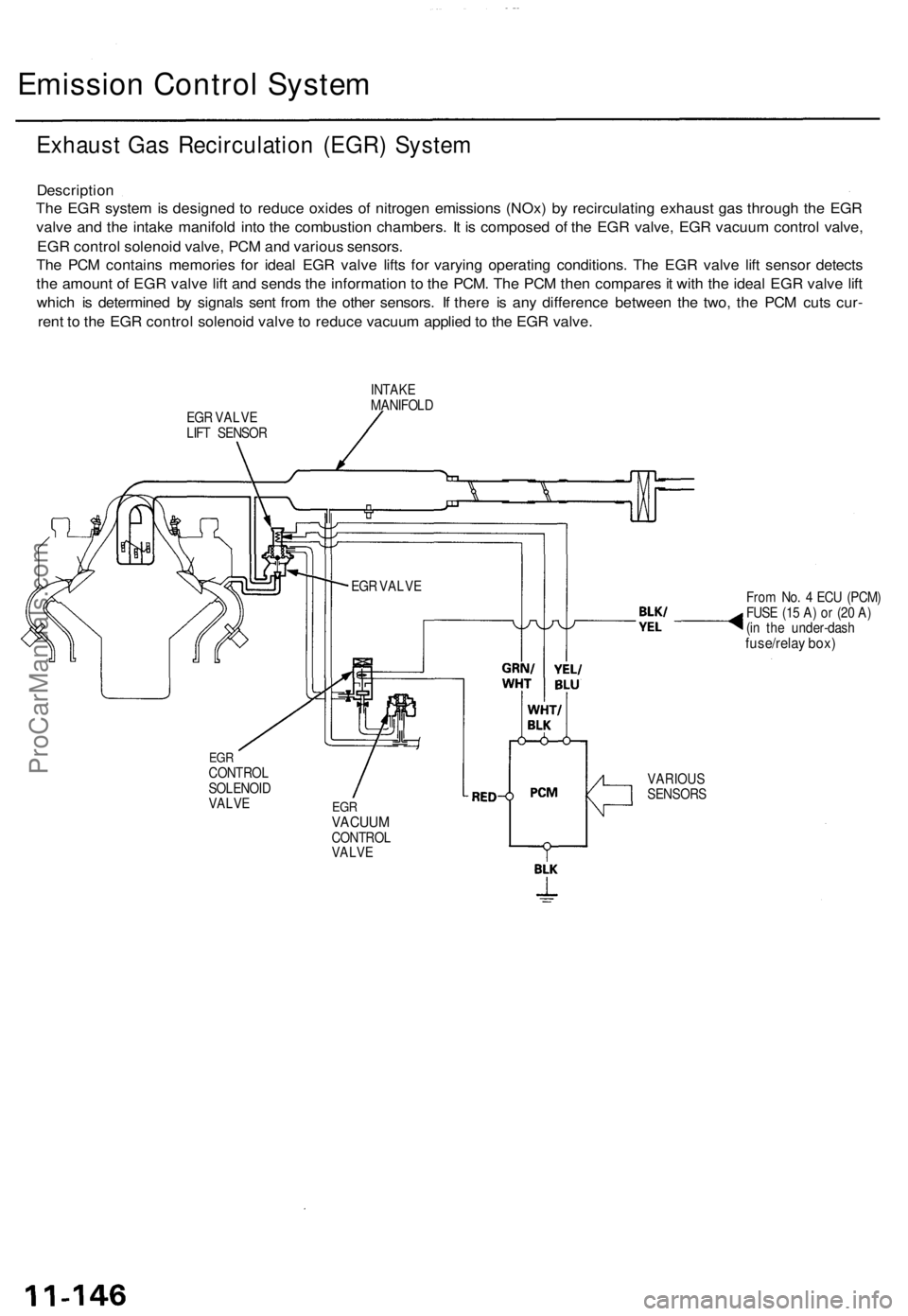
The EGR system is designed to reduce oxides of nitrogen emissions (NOx) by recirculating exhaust gas through the EGR
valve and the intake manifold into the combustion chambers. It is composed of the EGR valve, EGR vacuum control valve,
EGR control solenoid valve, PCM and various sensors.
The PCM contains memories for ideal EGR valve lifts for varying operating conditions. The EGR valve lift sensor detects
the amount of EGR valve lift and sends the information to the PCM. The PCM then compares it with the ideal EGR valve lift
which is determined by signals sent from the other sensors. If there is any difference between the two, the PCM cuts cur-
rent to the EGR control solenoid valve to reduce vacuum applied to the EGR valve.
EGR VALVE
LIFT SENSOR
INTAKE
MANIFOLD
From No. 4 ECU (PCM)
FUSE (15 A) or (20 A)
(in the under-dash
fuse/relay box)
EGR
CONTROL
SOLENOID
VALVE
EGR
VACUUM
CONTROL
VALVE
VARIOUS
SENSORS
EGR VALVEProCarManuals.com
Page 252 of 1771
Emission Control System
Positive Crankcase Ventilation (PCV) System
Description
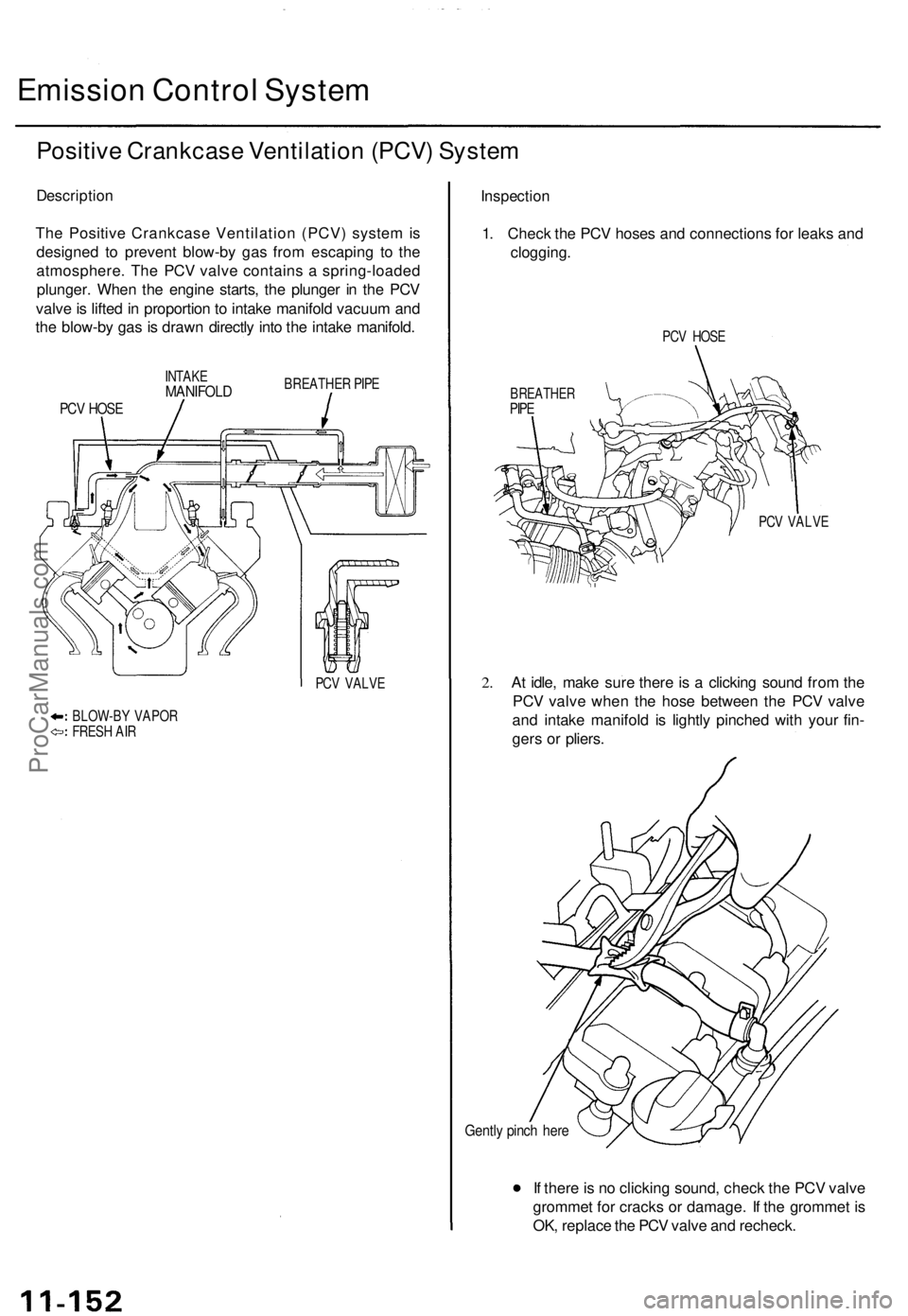
The Positive Crankcase Ventilation (PCV) system is
designed to prevent blow-by gas from escaping to the
atmosphere. The PCV valve contains a spring-loaded
plunger. When the engine starts, the plunger in the PCV
valve is lifted in proportion to intake manifold vacuum and
the blow-by gas is drawn directly into the intake manifold.
INTAKE
MANIFOLD
BREATHER PIPE
PCV HOSE
PCV VALVE
BLOW-BY VAPOR
FRESH AIR
Inspection
1. Check the PCV hoses and connections for leaks and
clogging.
PCV HOSE
BREATHER
PIPE
PCV VALVE
2.
At idle, make sure there is a clicking sound from the
PCV valve when the hose between the PCV valve
and intake manifold is lightly pinched with your fin-
gers or pliers.
Gently pinch here
If there is no clicking sound, check the PCV valve
grommet for cracks or damage. If the grommet is
OK, replace the PCV valve and recheck.ProCarManuals.com
Page 253 of 1771
Evaporative Emission (EVAP) Controls
Description
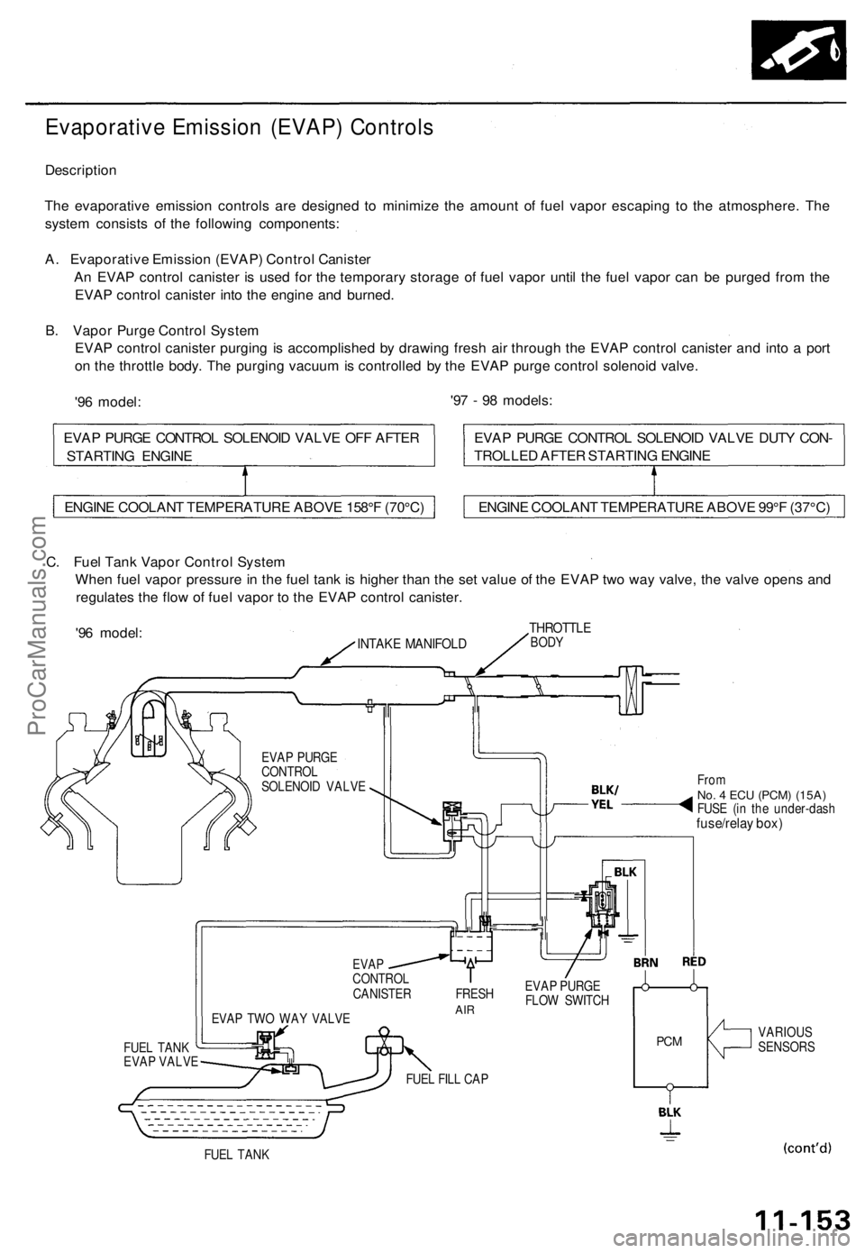
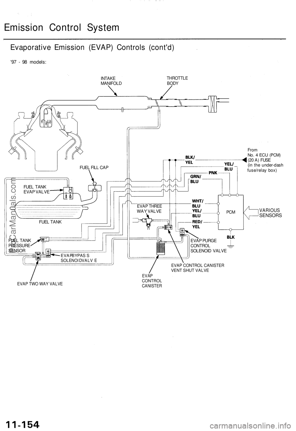
The evaporative emission controls are designed to minimize the amount of fuel vapor escaping to the atmosphere. The
system consists of the following components:
A. Evaporative Emission (EVAP) Control Canister
An EVAP control canister is used for the temporary storage of fuel vapor until the fuel vapor can be purged from the
EVAP control canister into the engine and burned.
B. Vapor Purge Control System
EVAP control canister purging is accomplished by drawing fresh air through the EVAP control canister and into a port
on the throttle body. The purging vacuum is controlled by the EVAP purge control solenoid valve.
'96 model:
'97 - 98 models:
C. Fuel Tank Vapor Control System
When fuel vapor pressure in the fuel tank is higher than the set value of the EVAP two way valve, the valve opens and
regulates the flow of fuel vapor to the EVAP control canister.
'96 model:
INTAKE MANIFOLD
THROTTLE
BODY
EVAP PURGE
CONTROL
SOLENOID VALVE
FUEL TANK
EVAP VALVE
EVAP TWO WAY VALVE
From
No. 4 ECU
(PCM) (15A)
FUSE (in the under-dash
fuse/relay box)
EVAP
CONTROL
CANISTER FRESH
AIR
EVAP PURGE
FLOW SWITCH
FUEL FILL CAP
PCM
VARIOUS
SENSORS
FUEL TANK
ENGINE COOLANT TEMPERATURE ABOVE 158°F (70°C)
ENGINE COOLANT TEMPERATURE ABOVE 99°F (37°C)
EVAP PURGE CONTROL SOLENOID VALVE DUTY CON-
TROLLED AFTER STARTING ENGINE
EVAP PURGE CONTROL SOLENOID VALVE OFF AFTER
STARTING ENGINEProCarManuals.com
Page 254 of 1771
Emission Contro l Syste m
Evaporativ e Emissio n (EVAP ) Control s (cont'd )
'97 - 9 8 models :
INTAKE
MANIFOL DTHROTTL EBODY
FromNo. 4 EC U (PCM )(20 A ) FUS E
(i n th e under-das h
fuse/rela y box )
EVAP CONTROL CANISTERVENT SHUT VALVE
EVAP TWO WAY VALVE
EVAPCONTROLCANISTER
VARIOU SSENSOR S
EVAP BYPAS SSOLENOI D VALV E
FUEL TAN K
FUE L TAN K
PRESSUR E
SENSO RFUE
L TAN K
EVA P VALV E FUE
L FIL L CA P
PCM
EVA P PURG ECONTRO LSOLENOI D VALV E
EVAP THRE EWAY VALV E
ProCarManuals.com
Page 255 of 1771
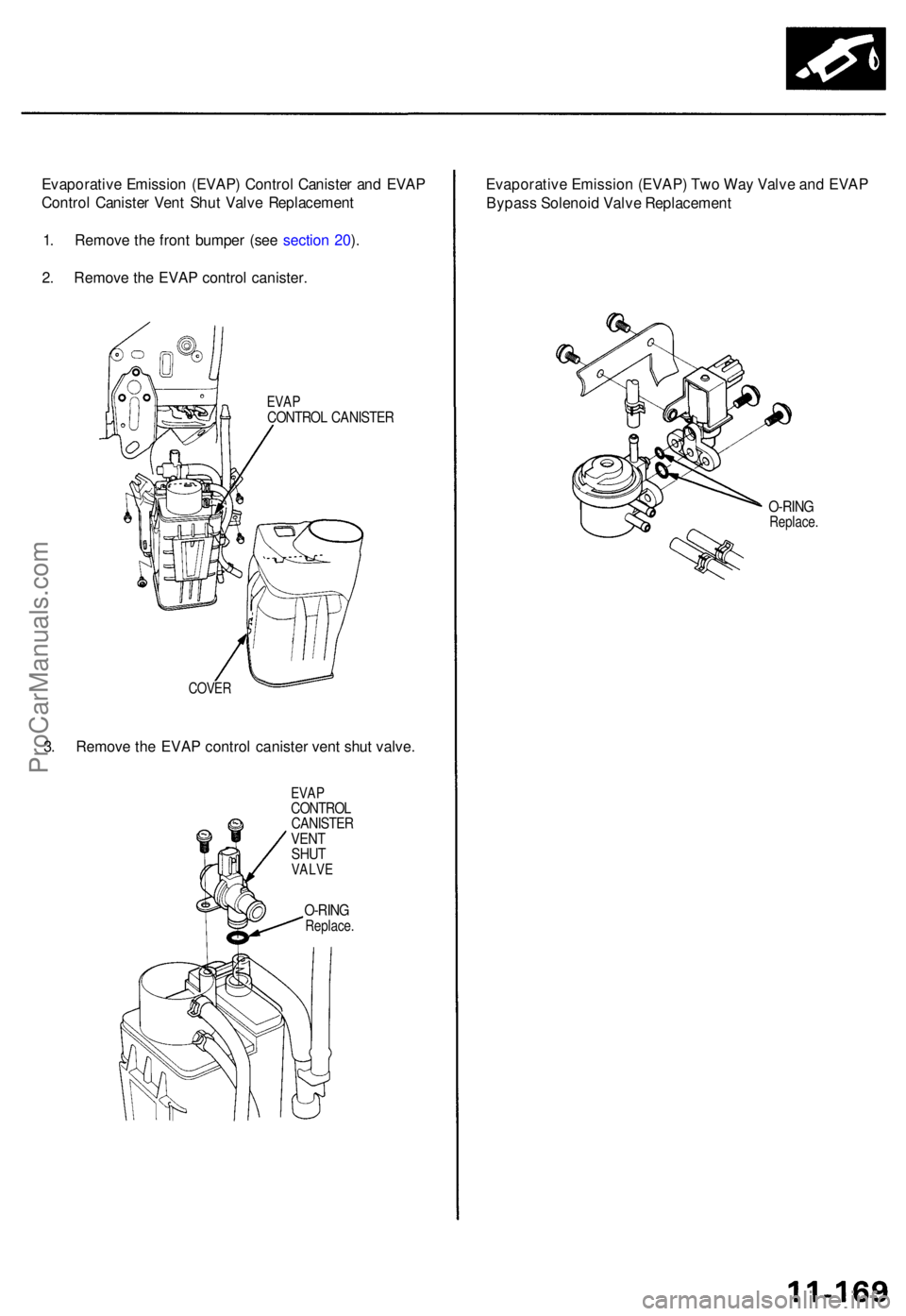
Evaporative Emissio n (EVAP ) Contro l Caniste r an d EVA P
Contro l Caniste r Ven t Shu t Valv e Replacemen t
1 . Remov e th e fron t bumpe r (se e sectio n 20 ).
2 . Remov e th e EVA P contro l canister .
EVAPCONTRO L CANISTE R
COVER
3. Remov e th e EVA P contro l caniste r ven t shu t valve .
EVAPCONTRO LCANISTERVENTSHUTVALV E
O-RINGReplace .
Evaporativ e Emissio n (EVAP ) Tw o Wa y Valv e an d EVA P
Bypas s Solenoi d Valv e Replacemen t
O-RINGReplace .
ProCarManuals.com
Page 256 of 1771
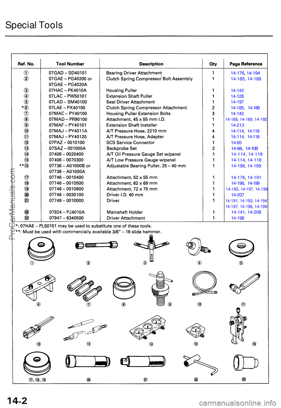
Special Tool s
14-176 , 14-19 4
14-185 , 14-18 8
14-14 3
14-12 8
14-19 7
14-185 , 14-18 8
14-14 3
14-168 , 14-169 , 14-192
14-21 3
14-114 , 14-11 8
14-114 , 14-11 8
14-65
14-66 , 14-10 8
14-114 , 14-11 8
14-114 , 14-11 8
14-198 , 14-19 9
14-176 , 14-19 1
14-198 , 14-19 9
14-193 , 14-197 , 14-198
14-20 7
14-191 , 14-193 , 14-194
14-197 , 14-198 , 14-199
14-141 , 14-20 8
14-19 8
ProCarManuals.com
Page 257 of 1771
Description
The automatic transmission is a combination of a 3-element torque converter and a dual-shaft electronically controlled
automatic transmission which provides 4 speeds forward and 1 reverse. The entire unit is positioned in line with the engine.
Torque Converter, Gears and Clutches
The torque converter consists of a pump, turbine, and stator, assembled in a single unit. They are connected to the engine
crankshaft so they turn together as a unit as the engine turns. Around the outside of the drive plate is a ring gear which
meshes with the starter pinion when the engine is being started.
The entire torque converter assembly serves as a flywheel while transmitting power to the transmission mainshaft.
The transmission has two parallel shafts: the mainshaft and the countershaft. The mainshaft is in line with the engine
crankshaft. The mainshaft includes the 1st, 4th and 2nd clutches and gears for 4th, 1st, 2nd and reverse (3rd gear is integral
with the mainshaft). The countershaft includes the 3rd, 1st-hold and reverse clutches, and gears for 3rd, 4th, 1st, 2nd,
reverse and parking. The secondary drive gear is integrated with the countershaft. The gears on the mainshaft are in con-
stant mesh with those on the countershaft. When certain combinations of gears in the transmission are engaged by clutch-
positions.
and
es, power is transmitted from the mainshaft to the countershaft to provide
Electronic Control
The electronic control system consists of a Powertrain Control Module (PCM), sensors, a linear solenoid and four solenoid
valves. Shifting and lock-up are electronically controlled for comfortable driving under all conditions.
The PCM is located below the dashboard, under the front lower panel on the passenger's side.
Hydraulic Control
The lower valve body assembly includes the main valve body, the secondary valve body, the throttle valve body, the lin-
ear solenoid, the shift control solenoid valves and the ATF passage body. They are bolted on the lower part of the trans-
mission housing. The regulator valve body, the ATF pump body, and the accumulator body are bolted to the torque con-
verter housing.
The main valve body on '96 model contains the manual valve, the 1-2 shift valve, the 2-3 shift valve, the 3-4 shift valve, the
4-3 kick-down valve and the Clutch Pressure Control (CPC) valve. The main valve body on '97 model contains the manual
valve, the 1-2 shift valve, the 2-3 shift valve, the 3-4 shift valve, the 4-3 kick-down valve and the main orifice control valve.
The secondary valve body on '96 model contains the 3-4 orifice control valve, the 4-3 shift timing valve, the modulator valve
and the accumulator pistons.The secondary valve body on '97 model contains the 3-4 orifice control valve, the 4-3 shift tim-
ing valve, the line pressure control valve, the modulator valve and the accumulator pistons. The throttle valve body
includes the throttle valve which is bolted onto the secondary valve body. The linear solenoid is joined to the throttle valve
body. The regulator valve body contains the regulator valve, the lock-up shift valve and the cooler relief valve. Fluid from
the regulator passes through the manual valve to the various control valves. The ATF pump body contains the lock-up tim-
ing valve, the lock-up control valve and the relief valve. The torque converter check valve is located in the torque converter
housing under the ATF pump body. The accumulator body contains the accumulator pistons. The reverse accumulator and
the 1st-hold accumulator pistons are assembled in the rear cover.
The 1st, 1st-hold, 2nd and reverse clutches receive fluid from their respective feed pipes, and the 3rd and 4th clutches
receive fluid from the internal hydraulic circuit.
Shift Control Mechanism
Input from various sensors located throughout the vehicle determines which shift control solenoid valve the PCM will acti-
vate. Activating a shift control solenoid valve changes modulator pressure, causing a shift valve to move. This pressurizes a
line to one of the clutches, engaging the clutch and its corresponding gear.
er through a fluid passage, causing the lock-up piston to be held against the torque converter cover. As this takes place, the
mainshaft rotates at the same speed as the engine crankshaft. Together with hydraulic control, the PCM optimizes the tim-
ing of the lock-up mechanism. The lock-up valves control the range of lock-up according to lock-up control solenoid valves
A and B, and throttle valve. When lock-up control solenoid valves A and B activate, modulator pressure changes. The lock-
up control solenoid valves A and B are mounted on the torque converter housing, and are controlled by the PCM.
(cont'd)
Lock-up Mechanism
In
position, in 2nd, 3rd, and 4th, and
position in 3rd, pressurized fluid is drained from the back of the torque convert-ProCarManuals.com
Page 258 of 1771
Description
(cont'd)
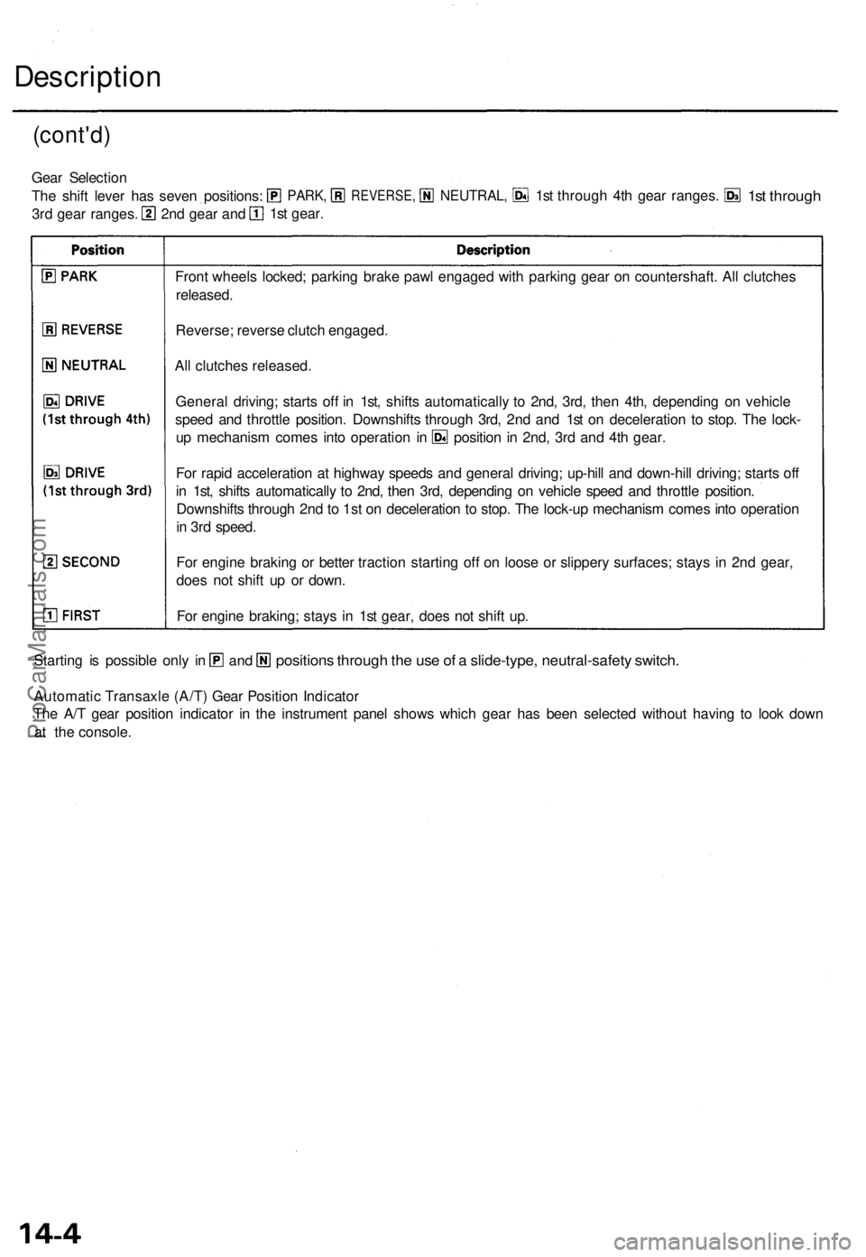
Front wheel s locked ; parkin g brak e paw l engage d wit h parkin g gea r o n countershaft . Al l clutche s
released .
Reverse ; revers e clutc h engaged .
Al l clutche s released .
Automati c Transaxl e (A/T ) Gea r Positio n Indicato r
Th e A/ T gea r positio n indicato r i n th e instrumen t pane l show s whic h gea r ha s bee n selecte d withou t havin g t o loo k dow n
a t the c onsole .
position s throug h th e us e o f a slide-type , neutral-safet y switch .Starting i s possibl e onl y i nan d
Gea r Selectio n
Th e shif t leve r ha s seve n positions :
3r d gea r ranges . 1s
t gear .
2n d gea r an d
PARK ,REVERSE ,NEUTRAL,1st throug h 4t h gea r ranges .1st throug h
For rapi d acceleratio n a t highwa y speed s an d genera l driving ; up-hil l an d down-hil l driving ; start s of f
i n 1st , shift s automaticall y t o 2nd , the n 3rd , dependin g o n vehicl e spee d an d throttl e position .
Downshift s throug h 2n d to
1st o n deceleratio n t o stop . Th e lock-u p mechanis m come s int o operatio n
i n 3r d speed .
Fo r engin e brakin g o r bette r tractio n startin g of f o n loos e o r slipper y surfaces ; stay s i n 2n d gear ,
doe s no t shif t u p o r down .
Fo r engin e braking ; stay s i n 1s t gear , doe s no t shif t up .
Genera
l driving ; start s of f i n 1st , shift s automaticall y t o 2nd , 3rd , the n 4th , dependin g o n vehicl e
spee d an d throttl e position . Downshift s throug h 3rd , 2n d an d 1s t o n deceleratio n t o stop . Th e lock -
u p mechanis m come s int o operatio n i n positio n in 2nd , 3r d an d 4t h gear .
ProCarManuals.com
Page 259 of 1771
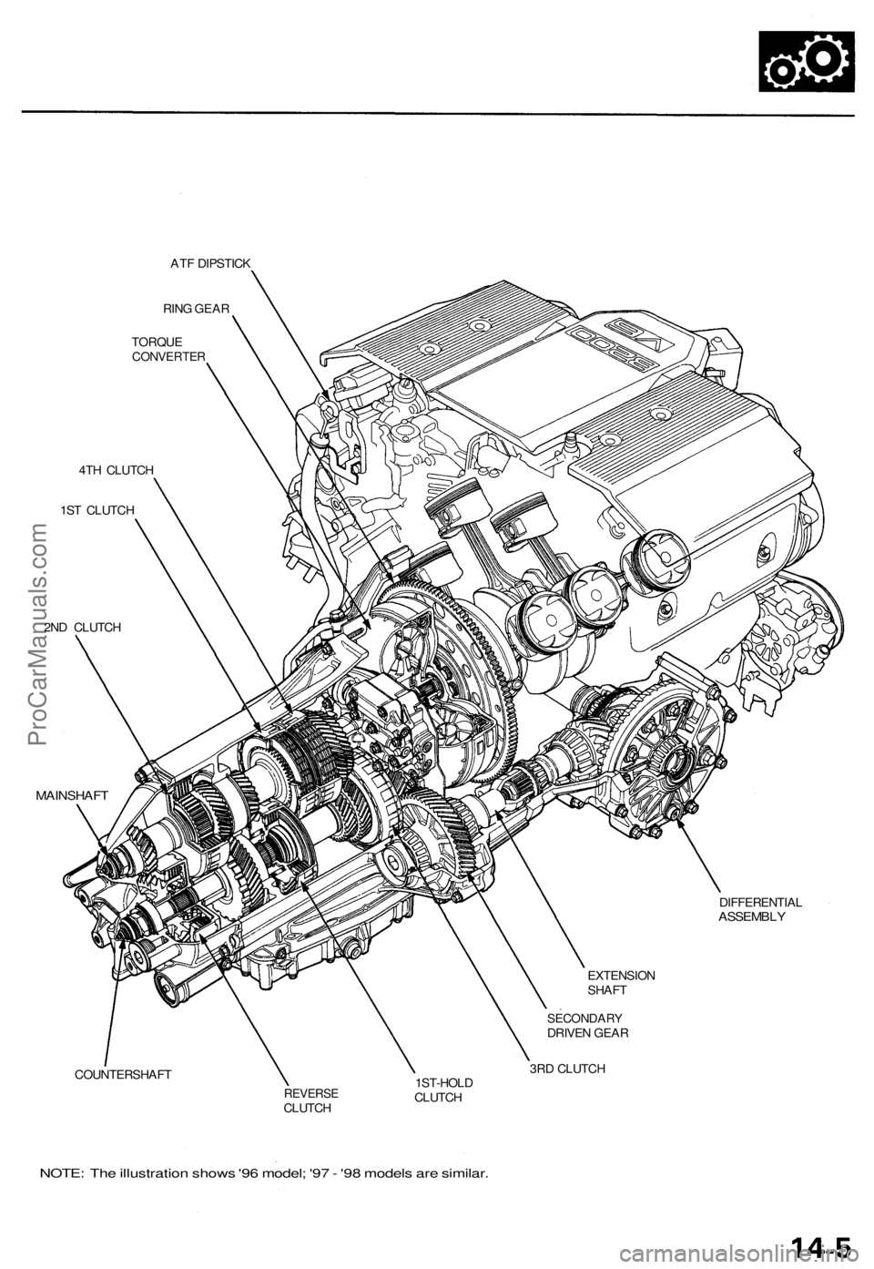
ATF DIPSTICK
RING GEAR
TORQUE
CONVERTER
4TH CLUTCH
1ST CLUTCH
2ND CLUTCH
MAINSHAFT
COUNTERSHAFT
EXTENSION
SHAFT
SECONDARY
DRIVEN GEAR
3RD CLUTCH
REVERSE
CLUTCH
1ST-HOLD
CLUTCH
DIFFERENTIAL
ASSEMBLY
NOTE: The illustration shows '96 model; '97 - '98 models are similar.ProCarManuals.com
Page 260 of 1771
Description
Clutches
The four-speed automatic transmission uses hydraulically-actuated clutches to engage or disengage the transmission gears.
When the hydraulic pressure is introduced into the clutch drum, the clutch piston moves. This presses the friction discs
and steel plates together, locking them so they don't slip. Power is then transmitted through the engaged clutch pack to its
hub-mounted gear.
Likewise, when the hydraulic pressure is bled from the clutch pack, the piston releases the friction discs and steel plates, and
they are free to slide past each. This allows the gear to spin independently of its shaft, transmitting no power.
1st Clutch
The 1st clutch, engages/disengages 1st gear, and is located at the middle of the mainshaft. The 1st clutch is joined back-to-
back to the 4th clutch. The 1st clutch is supplied hydraulic pressure by its ATF feed pipe within the mainshaft.
shaft. The 1st-hold clutch is supplied hydraulic pressure by its ATF feed pipe within the countershaft.
1st-hold Clutch
The 1st-hold clutch engages/disengages 1st-hold,
position or
position, and is located at the middle of the counter-
2nd Clutch
The 2nd clutch engages/disengages 2nd gear, and is located on the rear end of the mainshaft. The 2nd clutch is supplied
hydraulic pressure by its ATF feed pipe within the mainshaft.
3rd Clutch
The 3rd clutch engages/disengages 3rd gear, and is located at the end of the countershaft, opposite the rear cover. The
3rd clutch is supplied hydraulic pressure by a circuit connected to the internal hydraulic circuit.
4th Clutch
The 4th clutch engages/disengages 4th gear, and is located at the middle of the mainshaft. The 4th clutch is joined back-
to-back to the 1st clutch. The 4th clutch is supplied hydraulic pressure by a circuit connected to the internal hydraulic cir-
cuit.
Reverse Clutch
The reverse clutch engages/disengages reverse gear, and is located on the rear end of the countershaft. The reverse clutch is
supplied hydraulic pressure by its ATF feed pipe within the countershaft.
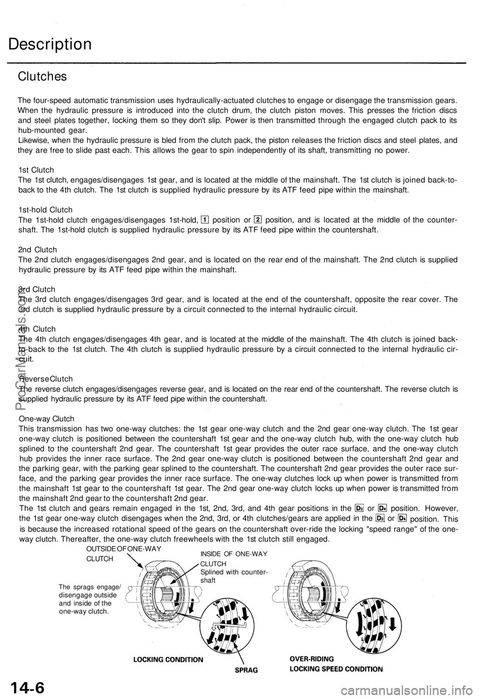
One-way Clutch
This transmission has two one-way clutches: the 1st gear one-way clutch and the 2nd gear one-way clutch. The 1st gear
one-way clutch is positioned between the countershaft 1st gear and the one-way clutch hub, with the one-way clutch hub
splined to the countershaft 2nd gear. The countershaft 1st gear provides the outer race surface, and the one-way clutch
hub provides the inner race surface. The 2nd gear one-way clutch is positioned between the countershaft 2nd gear and
the parking gear, with the parking gear splined to the countershaft. The countershaft 2nd gear provides the outer race sur-
face, and the parking gear provides the inner race surface. The one-way clutches lock up when power is transmitted from
the mainshaft 1st gear to the countershaft 1st gear. The 2nd gear one-way clutch locks up when power is transmitted from
the mainshaft 2nd gear to the countershaft 2nd gear.
The 1st clutch and gears remain engaged in the 1st, 2nd, 3rd, and 4th gear positions in the
the 1st gear one-way clutch disengages when the 2nd, 3rd, or 4th clutches/gears are applied in the
The sprags engage/
disengage outside
and inside of the
one-way clutch.
is because the increased rotational speed of the gears on the countershaft over-ride the locking "speed range" of the one-
way clutch. Thereafter, the one-way clutch freewheels with the 1st clutch still engaged.
INSIDE OF ONE-WAY
CLUTCH
Splined with counter-
shaft
OUTSIDE OF ONE-WAY
CLUTCH
position. However,
or
or
position. ThisProCarManuals.com