ACURA TL 1995 Service Repair Manual
Manufacturer: ACURA, Model Year: 1995, Model line: TL, Model: ACURA TL 1995Pages: 1771, PDF Size: 62.49 MB
Page 651 of 1771
Precautions/Procedures
Steering-related Precaution s
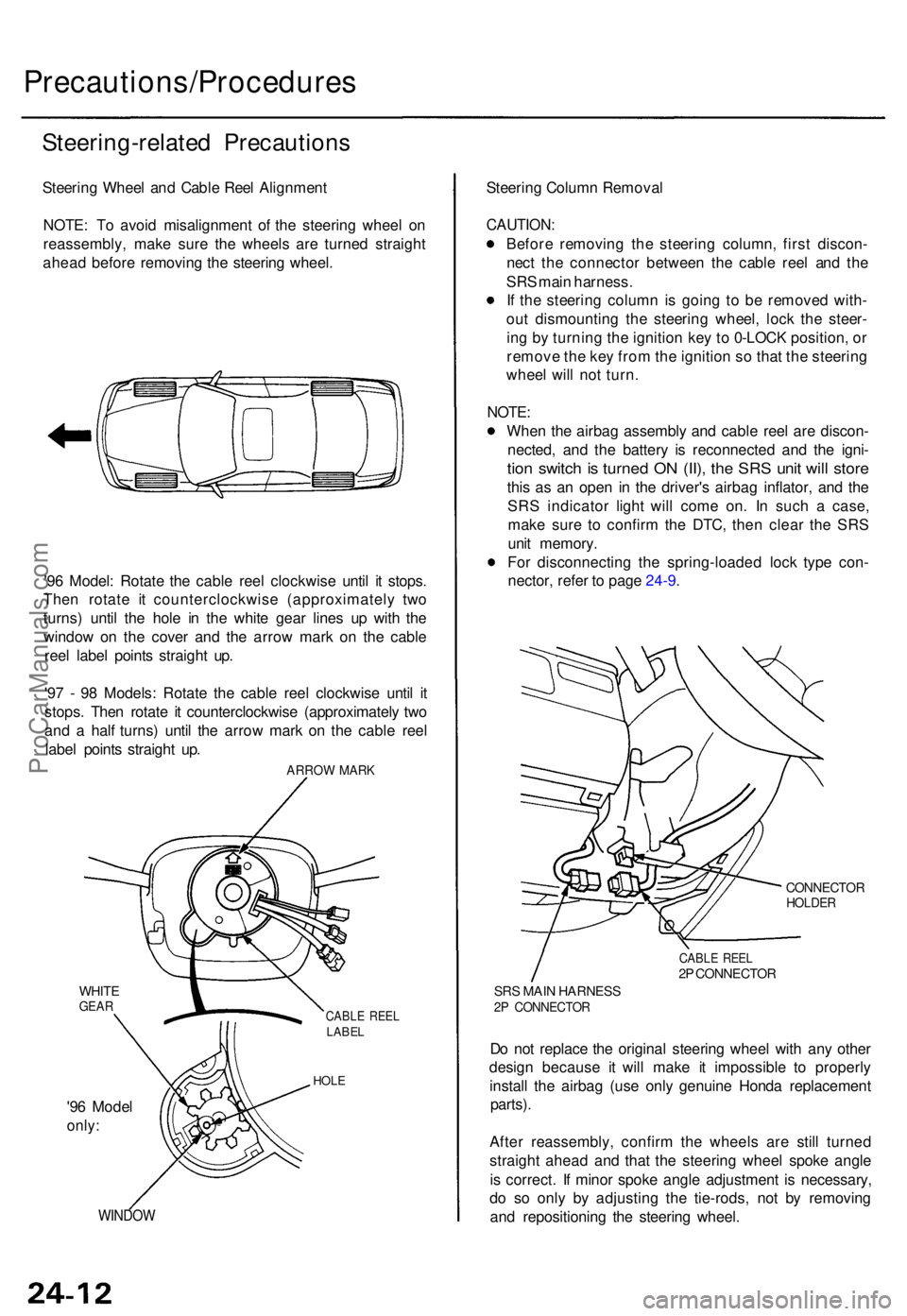
Steering Whee l an d Cabl e Ree l Alignmen t
NOTE : T o avoi d misalignmen t o f th e steerin g whee l o n
reassembly , mak e sur e th e wheel s ar e turne d straigh t
ahea d befor e removin g th e steerin g wheel .
'9 6 Model : Rotat e th e cabl e ree l clockwis e unti l i t stops .
The n rotat e i t counterclockwis e (approximatel y tw o
turns ) unti l th e hol e i n th e whit e gea r line s u p wit h th e
windo w o n th e cove r an d th e arro w mar k o n th e cabl e
ree l labe l point s straigh t up .
'9 7 - 9 8 Models : Rotat e th e cabl e ree l clockwis e unti l i t
stops . The n rotat e i t counterclockwis e (approximatel y tw o
an d a hal f turns ) unti l th e arro w mar k o n th e cabl e ree l
labe l point s straigh t up .
ARRO W MAR K
WHITEGEARCABL E REE LLABE L
HOLE
'96 Mode l
only:
WINDO W
Steering Colum n Remova l
CAUTION :
Before removin g th e steerin g column , firs t discon -
nec t th e connecto r betwee n th e cabl e ree l an d th e
SR S mai n harness .
I f th e steerin g colum n is goin g t o b e remove d with -
ou t dismountin g th e steerin g wheel , loc k th e steer -
in g b y turnin g th e ignitio n ke y t o 0-LOC K position , o r
remov e th e ke y fro m th e ignitio n s o tha t th e steerin g
whee l wil l no t turn .
NOTE :
Whe n th e airba g assembl y an d cabl e ree l ar e discon -
nected , an d th e batter y i s reconnecte d an d th e igni -
tion switc h is turne d O N (II) , th e SR S uni t wil l stor e
this a s a n ope n i n th e driver' s airba g inflator , an d th e
SR S indicato r ligh t wil l com e on . I n suc h a case ,
mak e sur e t o confir m th e DTC , the n clea r th e SR S
uni t memory .
Fo r disconnectin g th e spring-loade d loc k typ e con -
nector , refe r t o pag e 24-9 .
CONNECTO RHOLDER
CABLE REE L2P CONNECTO R
SRS MAI N HARNES S2P CONNECTO R
Do no t replac e th e origina l steerin g whee l wit h an y othe r
desig n becaus e i t will mak e i t impossibl e t o properl y
instal l th e airba g (us e onl y genuin e Hond a replacemen t
parts).
After reassembly , confir m th e wheel s ar e stil l turne d
straigh t ahea d an d tha t th e steerin g whee l spok e angl e
i s correct . I f mino r spok e angl e adjustmen t i s necessary ,
d o s o onl y b y adjustin g th e tie-rods , no t b y removin g
an d repositionin g th e steerin g wheel .
ProCarManuals.com
Page 652 of 1771
Troubleshooting
Self-diagnostic Procedure s
The self-diagnosti c functio n o f th e SR S syste m allow s i t t o locat e th e cause s o f syste m problem s an d t o stor e thi s informa -
tio n i n memory . Fo r easie r troubleshooting, this dat a ca n b e retrieve d vi a a dat a lin k circuit .
Whe n yo u tur n th e ignitio n switc h O N (II) , th e SR S indicato r wil l com e on . I f i t goe s of f afte r si x seconds , th e syste m is
normal .
I f ther e i s a n abnormality , th e syste m locate s an d define s th e problem , store s thi s informatio n i n memory , an d turn s
the SR S indicato r ligh t on .
NOTE : Th e dat a wil l remai n i n th e memor y eve n whe n th e ignitio n switc h i s turne d of f o r i f th e batter y i s disconnected .
Whe n yo u connec t th e SC S servic e connecto r t o th e servic e chec k connecto r (2P) , an d tur n th e ignitio n switc h O N (II) ,
th e SR S indicato r ligh t wil l indicat e th e diagnosti c troubl e cod e (DTC ) b y th e numbe r o f blinks .
Afte r readin g an d recordin g th e DTC , procee d wit h th e troubleshootin g fo r thi s code .
Precaution s
Use onl y a digita l multimete r t o chec k th e system . I f it' s no t a Hond a multimeter , mak e sur e it s outpu t i s 1 0 m A (0.0 1 A )
o r les s whe n switche d t o th e smalles t valu e i n th e ohmmete r range . A teste r wit h a highe r outpu t coul d damag e th e
airba g circui t o r caus e accidenta l airba g deploymen t an d possibl e injury -
Wheneve r th e ignitio n switc h i s O N (II) , o r ha s bee n turne d OF F fo r les s tha n thre e minutes , b e carefu l no t t o bum p th e
SR S unit ; th e airbag s coul d accidentall y deplo y an d caus e damag e o r injuries .
Befor e yo u remov e th e SR S mai n harness , disconnec t th e driver' s airba g connecto r an d th e fron t passenger' s airba g
connector . (Connec t th e Shor t connecto r (RED ) t o th e fron t passenger' s airba g connecto r o n a '9 6 model. )
Mak e sur e th e batter y i s sufficientl y charge d (se e sectio n 23 ). I f th e batter y i s dea d o r low , measurin g value s won' t b e
correct .
D o no t touc h a teste r prob e t o th e terminal s i n th e SR S uni t o r harnes s connectors , an d d o no t connec t th e terminal s
wit h a jumpe r wire . Us e onl y th e tes t harnes s an d th e SC S servic e connectors .
For backprobin g spring-loade d loc k typ e connectors , refe r t o pag e 24-11 .
ProCarManuals.com
Page 653 of 1771
Reading th e DT C
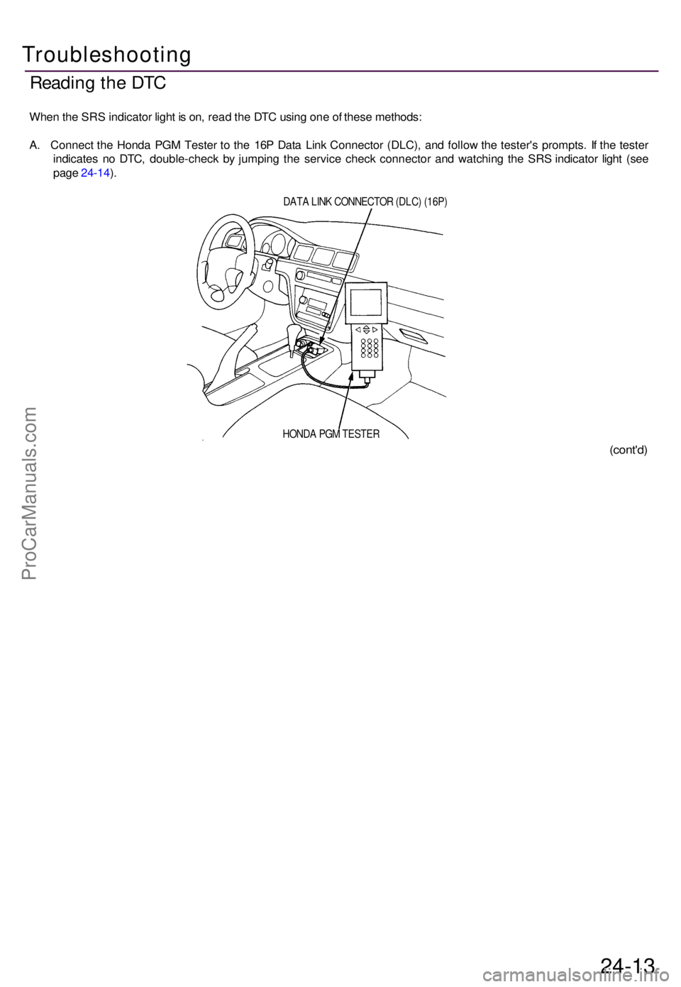
Whe n th e SR S indicato r ligh t i s on , rea d th e DT C usin g on e o f thes e methods :
A . Connec t th e Hond a PG M Teste r t o th e 16 P Dat a Lin k Connecto r (DLC) , an d follo w th e tester' s prompts . I f th e teste r
indicate s n o DTC , double-chec k b y jumpin g th e servic e chec k connecto r an d watchin g th e SR S indicato r ligh t (se e
page 24-14 ).
DAT A LIN K CONNECTO R (DLC ) (16P )
(cont'd )
24-13
HOND A PG M TESTE R
Troubleshooting
ProCarManuals.com
Page 654 of 1771
Troubleshooting
Reading th e DT C (cont'd )
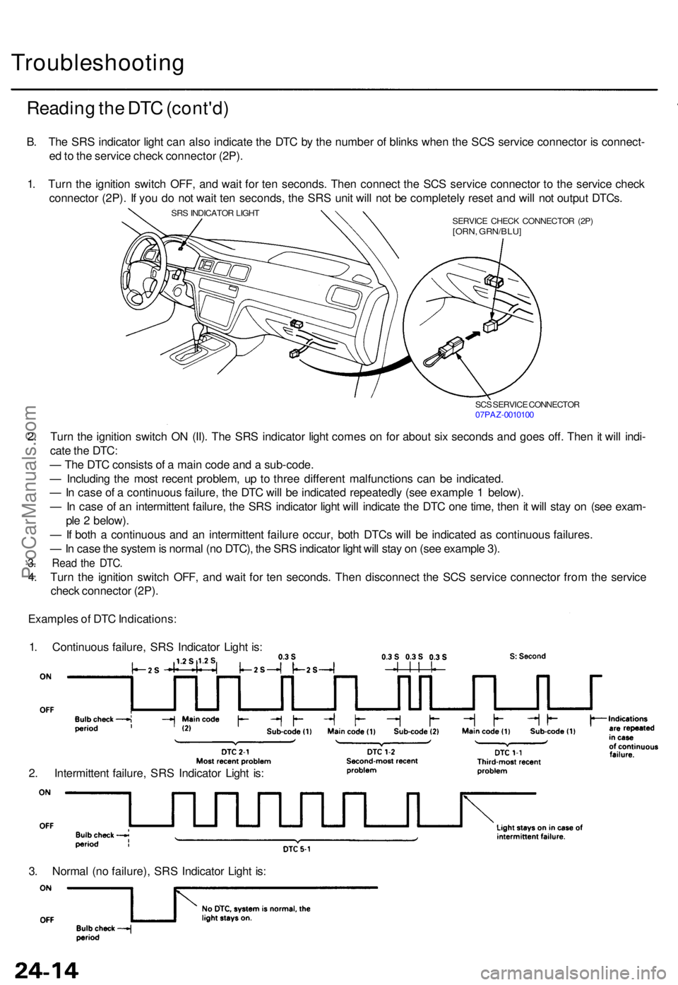
SCS SERVIC E CONNECTO R
07PA Z-001010 0
2. Tur n th e ignitio n switc h O N (II) . Th e SR S indicato r ligh t come s o n fo r abou t si x second s an d goe s off . The n it wil l indi -
cat e th e DTC :
— Th e DT C consist s o f a mai n cod e an d a sub-code .
— Includin g th e mos t recen t problem , u p t o thre e differen t malfunction s ca n b e indicated .
— In cas e o f a continuou s failure , th e DT C wil l b e indicate d repeatedl y (se e exampl e 1 below) .
— In cas e o f a n intermitten t failure , th e SR S indicato r ligh t wil l indicat e th e DT C on e time , the n it wil l sta y o n (se e exam -
pl e 2 below) .
— If bot h a continuou s an d a n intermitten t failur e occur , bot h DTC s wil l b e indicate d a s continuou s failures .
— In cas e th e syste m is norma l (n o DTC) , th e SR S indicato r ligh t wil l sta y o n (se e exampl e 3) .
3. Rea d th e DTC .
4. Tur n th e ignitio n switc h OFF , an d wai t fo r te n seconds . The n disconnec t th e SC S servic e connecto r fro m th e servic e
chec k connecto r (2P) .
Example s o f DT C Indications :
1 . Continuou s failure , SR S Indicato r Ligh t is :
2 . Intermitten t failure , SR S Indicato r Ligh t is :
3 . Norma l (n o failure) , SR S Indicato r Ligh t is :
B
. Th e SR S indicato r ligh t ca n als o indicat e th e DT C b y th e numbe r o f blink s whe n th e SC S servic e connecto r i s connect -
e d to th e servic e chec k connecto r (2P) .
1 . Tur n th e ignitio n switc h OFF , an d wai t fo r te n seconds . The n connec t th e SC S servic e connecto r t o th e servic e chec k
connecto r (2P) . I f yo u d o no t wai t te n seconds , th e SR S uni t wil l no t b e completel y rese t an d wil l no t outpu t DTCs .
SRS INDICATO R LIGH T
SERVICE CHEC K CONNECTO R (2P )
[ORN , GRN/BLU ]
ProCarManuals.com
Page 655 of 1771
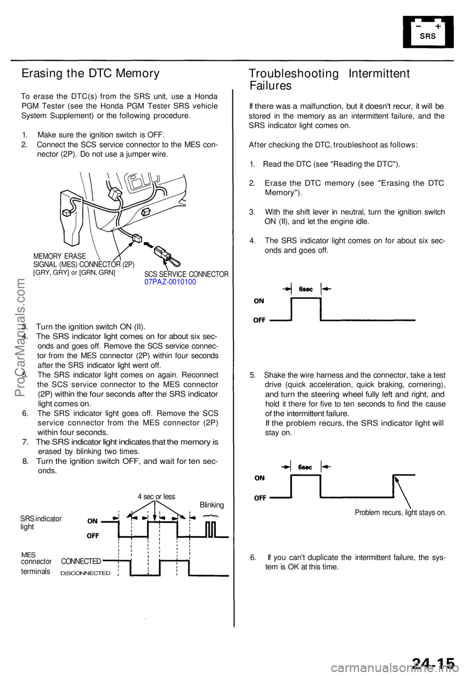
Erasing th e DT C Memor y
To eras e th e DTC(s ) fro m th e SR S unit , us e a Hond a
PG M Teste r (se e th e Hond a PG M Teste r SR S vehicl e
Syste m Supplement ) o r th e followin g procedure .
1 . Mak e sur e th e ignitio n switc h i s OFF .
2 . Connec t th e SC S servic e connecto r t o th e ME S con -
necto r (2P) . D o no t us e a jumpe r wire .
MEMOR Y ERAS ESIGNAL (MES ) CONNECTO R (2P )[GRY , GRY ] or [GRN , GRN ]SCS SERVIC E CONNECTO R07PAZ-001010 0
3. Tur n th e ignitio n switc h O N (II) .
4. Th e SR S indicato r ligh t come s o n fo r abou t si x sec -
onds an d goe s off . Remov e th e SC S servic e connec -
to r fro m th e ME S connecto r (2P ) withi n fou r second s
afte r th e SR S indicato r ligh t wen t off .
5 . Th e SR S indicato r ligh t come s o n again . Reconnec t
th e SC S servic e connecto r t o th e ME S connecto r
(2P) withi n th e fou r second s afte r th e SR S indicato r
light come s on .
6. Th e SR S indicato r ligh t goe s off . Remov e th e SC S
servic e connecto r fro m th e ME S connecto r (2P )
within fou r seconds .
7. Th e SR S indicato r ligh t indicate s tha t th e memor y is
erase d b y blinkin g tw o times .
8. Tur n th e ignitio n switc h OFF , an d wai t fo r te n sec -
onds .
4 se c o r les sBlinkin g
SRS indicato rlight
MESconnecto r CONNECTE D
terminals D|SCONNECTE D
Troubleshooting Intermitten t
Failures
If ther e wa s a malfunction , bu t i t doesn' t recur , i t wil l b e
store d i n th e memor y a s a n intermitten t failure , an d th e
SR S indicato r ligh t come s on .
Afte r checkin g th e DTC , troubleshoo t a s follows :
1 . Rea d th e DT C (se e "Readin g th e DTC") .
2. Eras e th e DT C memor y (se e "Erasin g th e DT C
Memory") .
3. Wit h th e shif t leve r i n neutral , tur n th e ignitio n switc h
O N (II) , an d le t th e engin e idle .
4 . Th e SR S indicato r ligh t come s o n fo r abou t si x sec -
ond s an d goe s off .
5 . Shak e th e wir e harnes s an d th e connector , tak e a tes t
driv e (quic k acceleration , quic k braking , cornering) ,
and tur n th e steerin g whee l full y lef t an d right , an d
hold i t ther e fo r fiv e t o te n second s t o fin d th e caus e
of th e intermitten t failure .
If th e proble m recurs , th e SR S indicato r ligh t wil l
stay on .
Proble m recurs , ligh t stay s on .
6. I f yo u can' t duplicat e th e intermitten t failure , th e sys -
te m is O K a t thi s time .
ProCarManuals.com
Page 656 of 1771
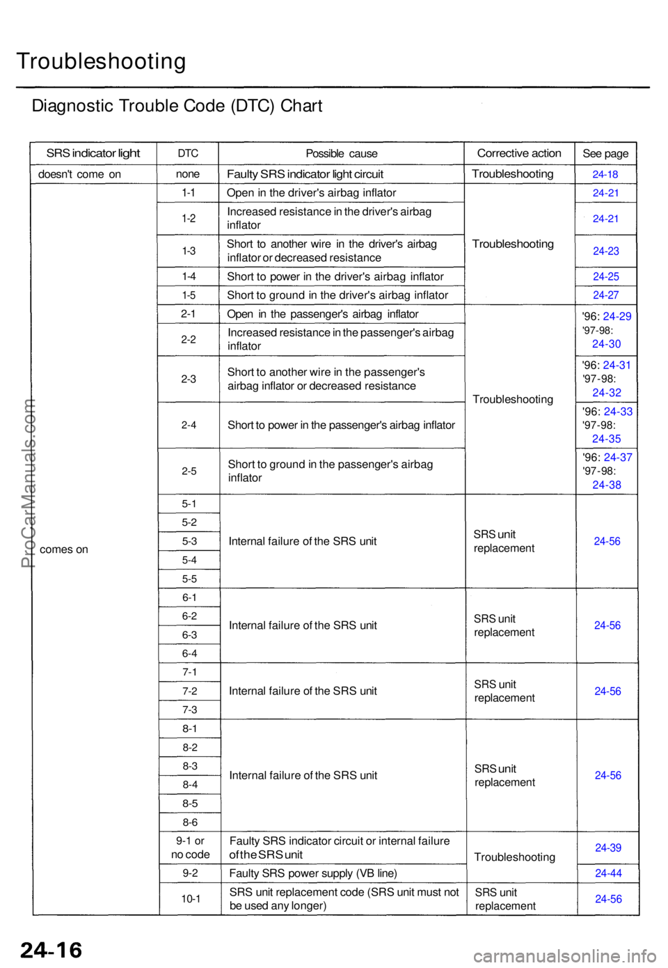
Troubleshooting
Diagnostic Troubl e Cod e (DTC ) Char t
SRS indicato r light
doesn' t com e o n
come s o n
DT C
non e
1-1
1- 2
1-3
1- 4
1-5
2- 1
2- 2
2-3
2- 4
2-5
5-1
5-2
5-3
5- 4
5-5
6-1
6- 2
6-3
6- 4
7- 1
7-2
7-3
8-1
8- 2
8-3
8- 4
8-5
8- 6
9- 1 o r
no cod e
9-2
10- 1
Possibl e caus e
Faulty SR S indicato r ligh t circui t
Open in th e driver' s airba g inflato r
Increase d resistanc e in th e driver' s airba g
inflato r
Shor t t o anothe r wir e i n th e driver' s airba g
inflato r o r decrease d resistanc e
Shor t t o powe r i n th e driver' s airba g inflato r
Shor t t o ground in th e driver' s airba g inflato r
Ope n i n th e passenger' s airba g inflato r
Increase d resistanc e in th e passenger' s airba g
inflato r
Shor t t o anothe r wir e in th e passenger' s
airba g inflato r o r decrease d resistanc e
Shor t t o powe r i n th e passenger' s airba g inflato r
Shor t t o groun d in th e passenger' s airba g
inflato r
Interna l failur e o f th e SR S uni t
Interna l failur e o f th e SR S uni t
Interna l failur e o f th e SR S uni t
Interna l failur e o f th e SR S uni t
Fault y SR S indicato r circui t o r interna l failur e
of th e SR S uni t
Fault y SR S powe r suppl y (V B line )
SR S uni t replacemen t cod e (SR S uni t mus t no t
b e use d an y longer )
Correctiv e actio n
Troubleshootin g
Troubleshootin g
Troubleshootin g
SRS uni t
replacemen t
SRS uni t
replacemen t
SRS uni t
replacemen t
SRS unit
replacemen t
Troubleshootin g
SRS uni t
replacemen t
See pag e
24-1 8
24-2 1
24-21
24-2 3
24-2 5
24-27
'96: 24-2 9
'97-98:
24-3 0
'96: 24-3 1
'97 - 98 :
24-3 2
'96: 24-3 3
'97 - 98 :
24-3 5
'96: 24-3 7
'97 - 98 :
24-3 8
24-56
24-5 6
24-56
24-5 6
24-39
24-4 4
24-5 6
ProCarManuals.com
Page 657 of 1771
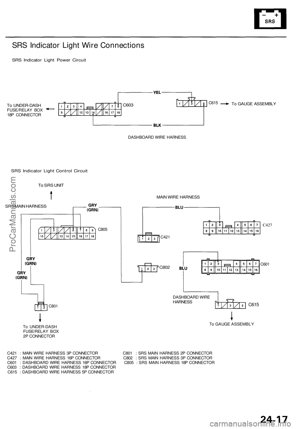
SRS Indicato r Ligh t Wir e Connection s
SRS Indicato r Ligh t Powe r Circui t
To UNDER-DAS HFUSE/RELAY BO X
18 P CONNECTO R
To GAUG E ASSEMBL Y
DASHBOAR D WIR E HARNES S
SRS Indicato r Ligh t Contro l Circui t
To SR S UNI T
SRS MAI N HARNES S
C801
To UNDER-DAS H
FUSE/RELA Y BO X
2 P CONNECTO R
C421
C427
C60 1
C42 1 : MAI N WIR E HARNES S 3 P CONNECTO R C80 1 : SR S MAI N HARNES S 2 P CONNECTO R
C42 7 : MAI N WIR E HARNES S 16 P CONNECTO R C80 2 : SR S MAI N HARNES S 3 P CONNECTO R
C60 1 : DASHBOAR D WIR E HARNES S 16 P CONNECTO R C80 5 : SR S MAI N HARNES S 18 P CONNECTO R
C60 3 : DASHBOAR D WIR E HARNES S 18 P CONNECTO R
C61 5 : DASHBOAR D WIR E HARNES S 5 P CONNECTO R
C615
C802
MAIN WIR E HARNES S
C805
DASHBOARD WIR E
HARNES S
C615C60 3
To GAUG E ASSEMBL Y
ProCarManuals.com
Page 658 of 1771
Airbag
Replacement
After a collision in which the airbags were deployed, the
airbag assemblies and the SRS unit must be replaced.
Store a removed airbag assembly with
the pad surface up. If the airbag is improperly stored
face down, accidental deployment could propel the unit
with enough force to cause serious injury.
CAUTION:
Always disconnect the airbag connectors when the
SRS main harness is disconnected.
'96 Model: Always keep the short connector (RED) on
the passenger's airbag when the harness is discon-
nected.
Do not disassemble or tamper with the airbag.
NOTE:
Do not install used SRS parts from another vehicle.
When repairing, use only new SRS parts.
Carefully inspect the airbag before you install it. Do
not install an airbag that shows signs of being
dropped or improperly handled, such as dents, cracks
or deformation.
1. Make sure you have the anti-theft code for the radio,
then write down the frequencies for the radio's pre-
set buttons.
2. Disconnect the battery negative cable, then discon-
nect the positive cable from the battery, and wait at
least three minutes.
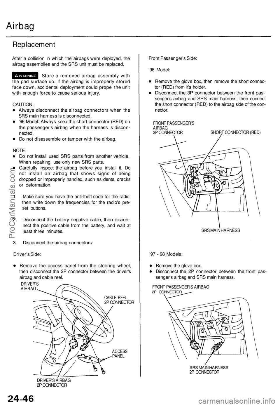
3. Disconnect the airbag connectors:
Driver's Side:
Remove the access panel from the steering wheel,
then disconnect the 2P connector between the driver's
airbag and cable reel.
ACCESS
PANEL
Front Passenger's Side:
'96 Model:
Remove the glove box, then remove the short connec-
tor (RED) from it's holder.
Disconnect the 3P connector between the front pas-
senger's airbag and SRS main harness, then connect
the short connector (RED) to the airbag side of the con-
nector.
FRONT PASSENGER'S
AIRBAG
3P CONNECTOR
SHORT CONNECTOR (RED)
SRS MAIN HARNESS
'97 - 98 Models:
Remove the glove box.
Disconnect the 2P connector between the front pas-
senger's airbag and SRS main harness.
FRONT PASSENGER'S AIRBAG
2P CONNECTOR
SRS MAIN HARNESS
2P CONNECTOR
DRIVER'S AIRBAG
2P CONNECTOR
CABLE REEL
2P CONNECTOR
DRIVER'S
AIRBAG.ProCarManuals.com
Page 659 of 1771
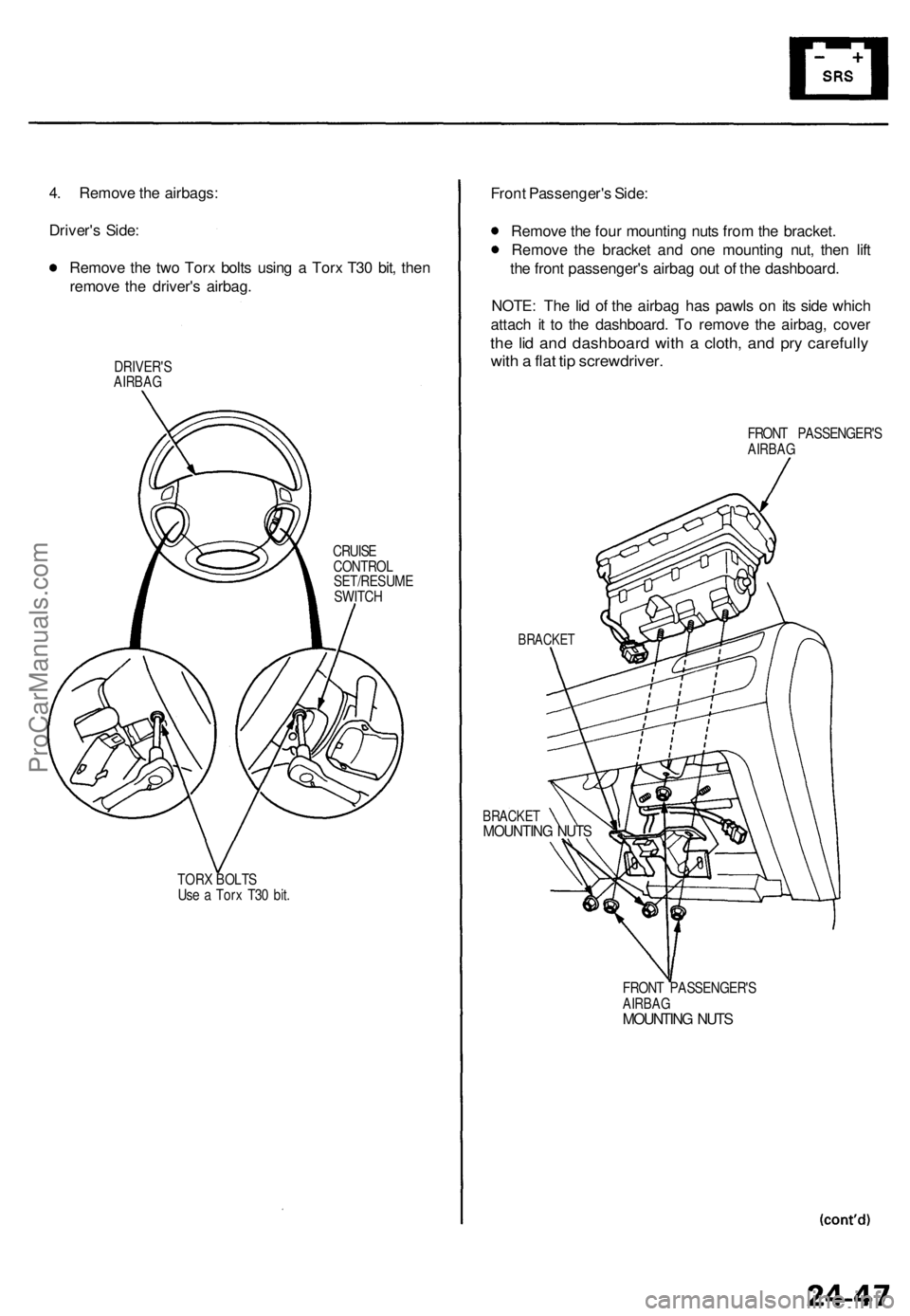
4. Remove the airbags:
Driver's Side:
Remove the two Torx bolts using a Torx T30 bit, then
remove the driver's airbag.
DRIVER'S
AIRBAG
CRUISE
CONTROL
SET/RESUME
SWITCH
TORX BOLTS
Use a Torx T30 bit.
Front Passenger's Side:
Remove the four mounting nuts from the bracket.
Remove the bracket and one mounting nut, then lift
the front passenger's airbag out of the dashboard.
NOTE: The lid of the airbag has pawls on its side which
attach it to the dashboard. To remove the airbag, cover
the lid and dashboard with a cloth, and pry carefully
with a flat tip screwdriver.
FRONT PASSENGER'S
AIRBAG
BRACKET
BRACKET
MOUNTING NUTS
FRONT PASSENGER'S
AIRBAG
MOUNTING NUTSProCarManuals.com
Page 660 of 1771
Airbag
Replacement (cont'd)
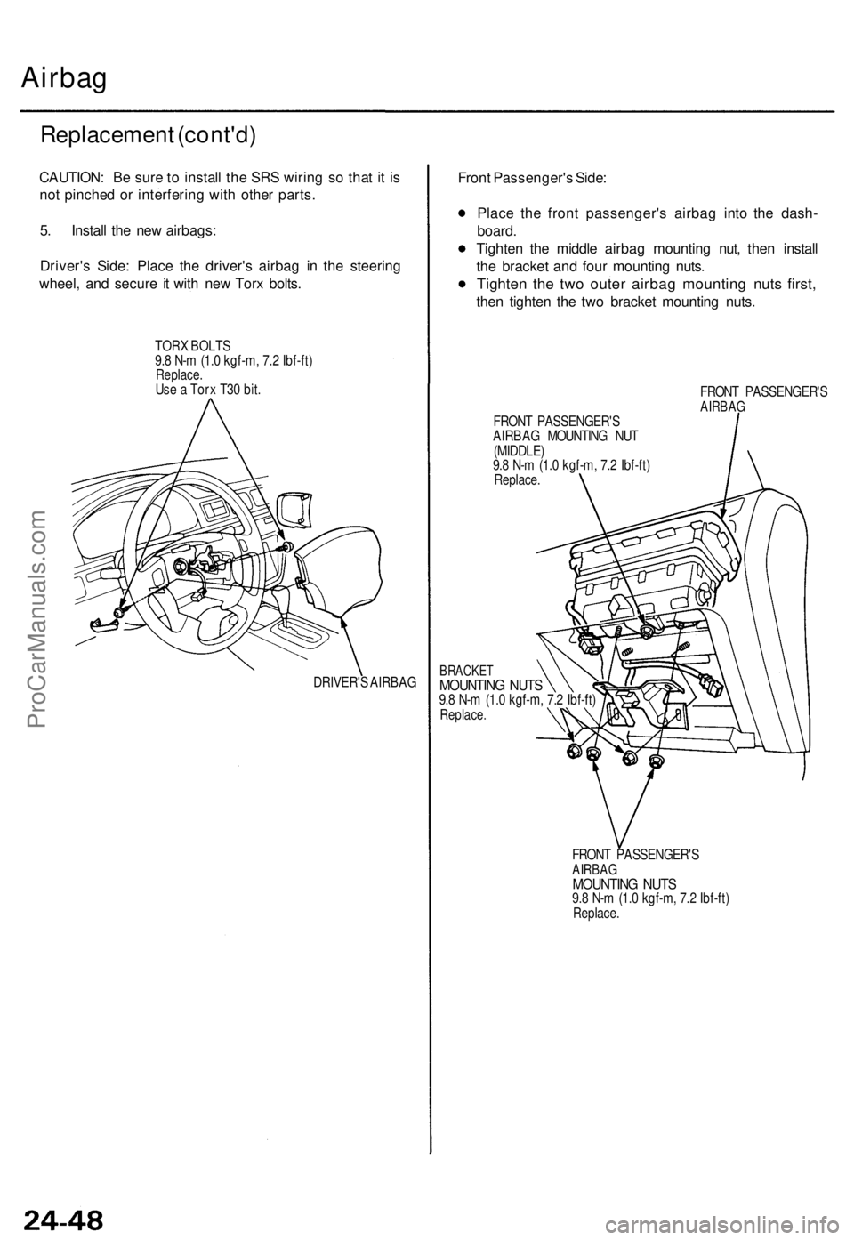
CAUTION: Be sure to install the SRS wiring so that it is
not pinched or interfering with other parts.
5. Install the new airbags:
Driver's Side: Place the driver's airbag in the steering
wheel, and secure it with new Torx bolts.
TORX BOLTS
9.8 N-m (1.0 kgf-m, 7.2 Ibf-ft)
Replace.
Use a Torx T30 bit.
DRIVER'S AIRBAG
Front Passenger's Side:
Place the front passenger's airbag into the dash-
board.
Tighten the middle airbag mounting nut, then install
the bracket and four mounting nuts.
Tighten the two outer airbag mounting nuts first,
then tighten the two bracket mounting nuts.
FRONT PASSENGER'S
AIRBAG
FRONT PASSENGER'S
AIRBAG MOUNTING NUT
(MIDDLE)
9.8 N-m (1.0 kgf-m, 7.2 Ibf-ft)
Replace.
BRACKET
MOUNTING NUTS
9.8 N-m (1.0 kgf-m, 7.2 Ibf-ft)
Replace.
FRONT PASSENGER'S
AIRBAG
MOUNTING NUTS
9.8 N-m (1.0 kgf-m, 7.2 Ibf-ft)
Replace.ProCarManuals.com