ACURA TL 1995 Service Repair Manual
Manufacturer: ACURA, Model Year: 1995, Model line: TL, Model: ACURA TL 1995Pages: 1771, PDF Size: 62.49 MB
Page 761 of 1771
Valves, Valve Springs and Valv e Seal s
Remova l (cont'd )
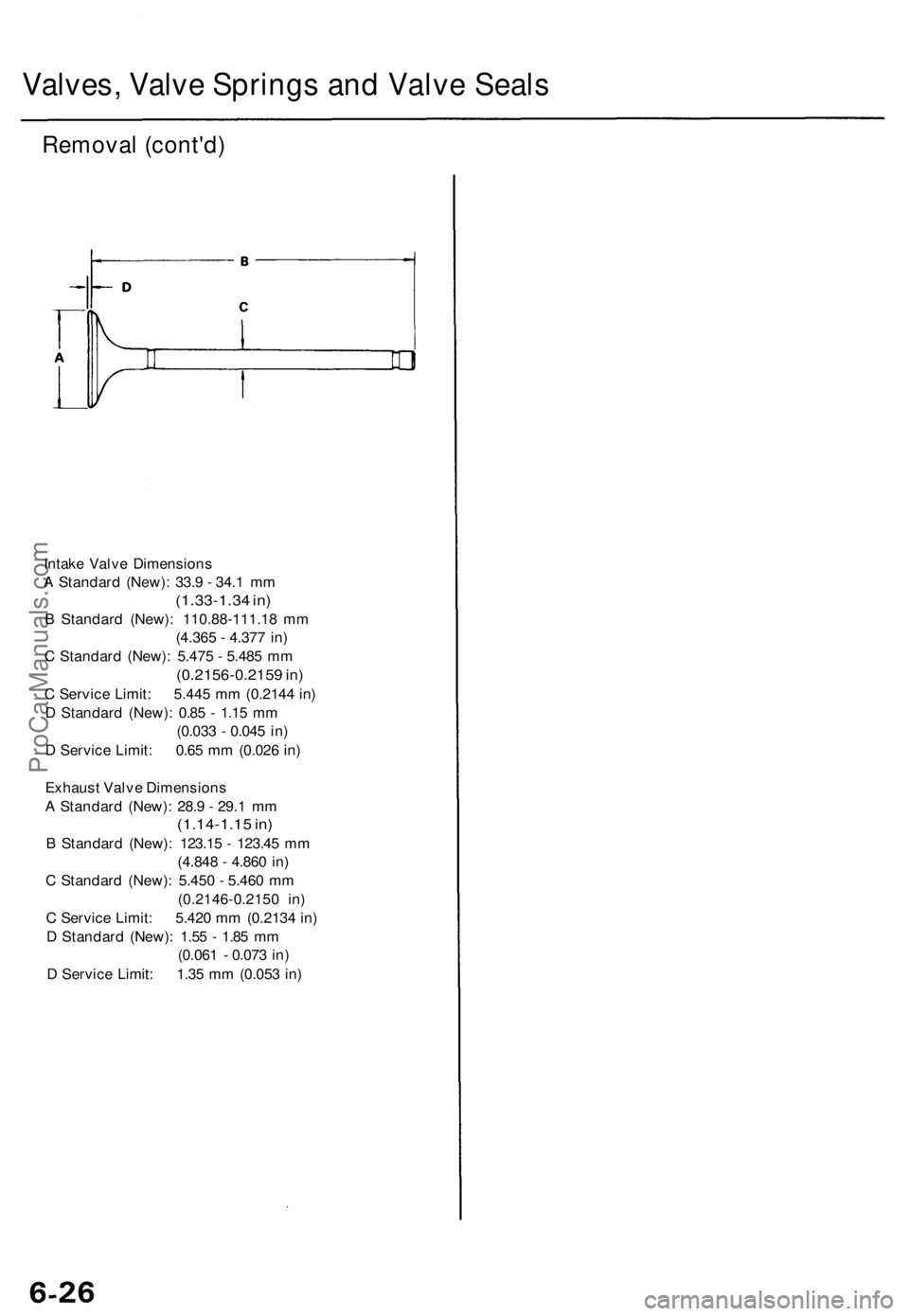
Intake Valv e Dimension s
A Standar d (New) : 33. 9 - 34. 1 m m
(1.33-1.3 4 in )
B Standar d (New) : 110.88-111.1 8 m m
(4.36 5 - 4.37 7 in )
C Standar d (New) : 5.47 5 - 5.48 5 m m
(0.2156-0.215 9 in )
C Servic e Limit : 5.44 5 m m (0.214 4 in )
D Standar d (New) : 0.8 5 - 1.1 5 m m
(0.03 3 - 0.04 5 in )
D Servic e Limit : 0.6 5 m m (0.02 6 in )
Exhaus t Valv e Dimension s
A Standar d (New) : 28. 9 - 29. 1 m m
(1.14-1.1 5 in )
B Standar d (New) : 123.1 5 - 123.4 5 m m
(4.84 8 - 4.86 0 in )
C Standar d (New) : 5.45 0 - 5.46 0 m m
(0.2146-0.215 0 in )
C Servic e Limit : 5.42 0 m m (0.213 4 in )
D Standar d (New) : 1.5 5 - 1.8 5 m m
(0.06 1 - 0.07 3 in )
D Servic e Limit : 1.3 5 m m (0.05 3 in )
ProCarManuals.com
Page 762 of 1771
Cylinder Hea d
Warpag e
NOTE: I f th e camshaft-to-holde r oi l clearanc e (se e
pag e 6-22 ) i s no t withi n specifications , th e cylinde r hea d
canno t b e resurfaced .
I f th e camshaft-to-holde r oi l clearanc e i s withi n specifi -
cations , chec k th e cylinde r hea d fo r warpage .
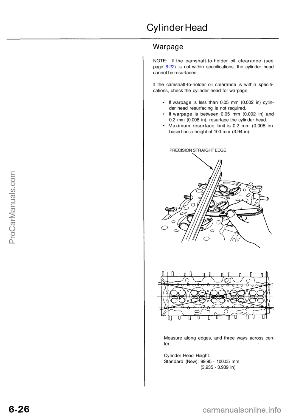
• I f warpag e i s les s tha n 0.0 5 m m (0.00 2 in ) cylin -
de r hea d resurfacin g i s no t required .
• I f warpag e i s betwee n 0.0 5 m m (0.00 2 in ) an d
0. 2 m m (0.00 8 in) , resurfac e th e cylinde r head .
• Maximu m resurfac e limi t i s 0. 2 m m (0.00 8 in )
base d o n a heigh t o f 10 0 m m (3.9 4 in) .
PRECISIO N STRAIGH T EDG E
Measur e alon g edges , an d thre e way s acros s cen -
ter.
Cylinde r Hea d Height :
Standar d (New) : 99.9 5 - 100.0 5 m m
(3.93 5 - 3.93 9 in )
ProCarManuals.com
Page 763 of 1771
Valve Guides
Valve Movement
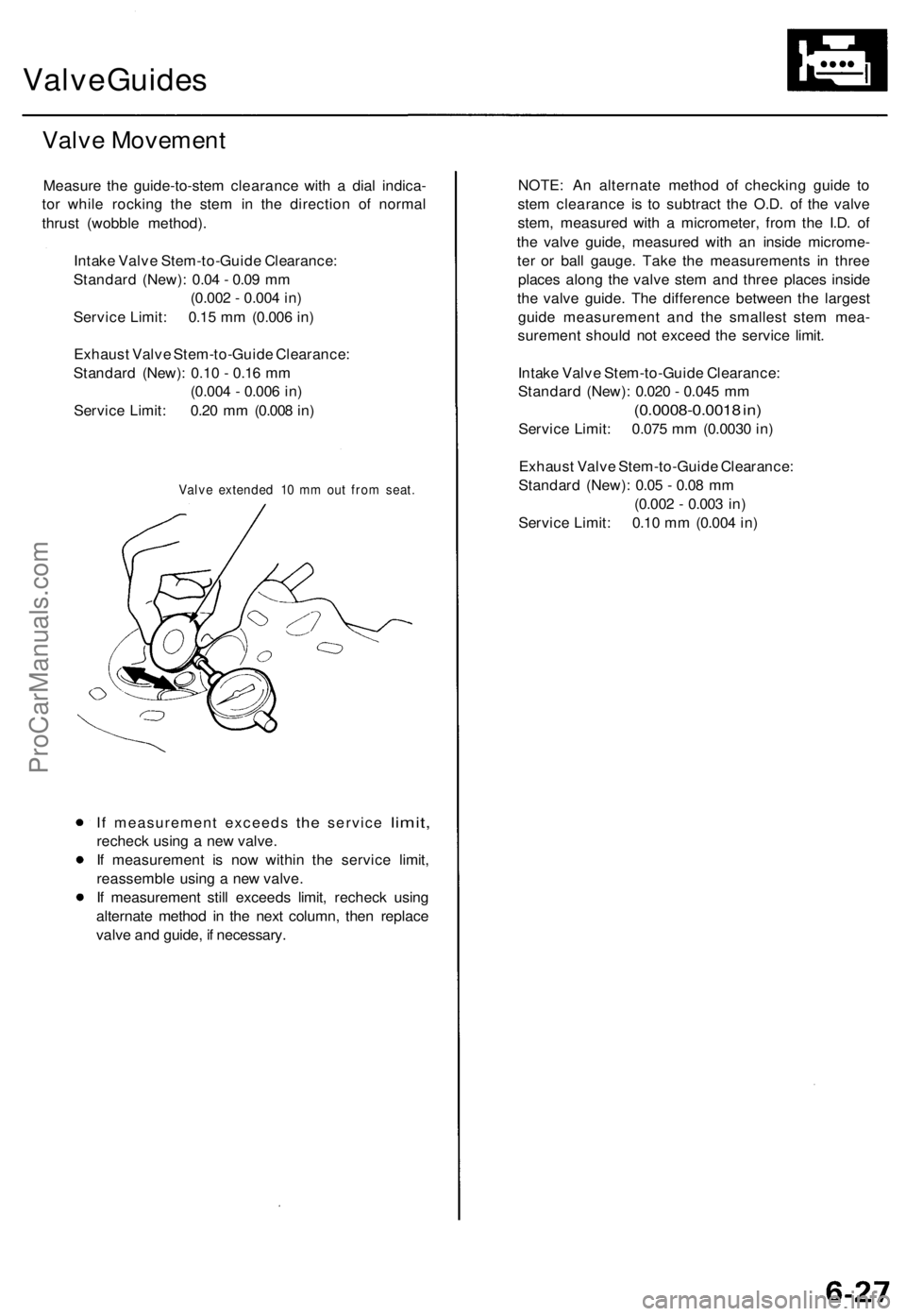
Measure the guide-to-stem clearance with a dial indica-
tor while rocking the stem in the direction of normal
thrust (wobble method).
Intake Valve Stem-to-Guide Clearance:
Standard (New): 0.04 - 0.09 mm
(0.002 - 0.004 in)
Service Limit: 0.15 mm (0.006 in)
Exhaust Valve Stem-to-Guide Clearance:
Standard (New): 0.10 - 0.16 mm
(0.004 - 0.006 in)
Service Limit: 0.20 mm (0.008 in)
Valve extended 10 mm out from seat.
If
measurement exceeds
the
service
limit,
recheck using a new valve.
If measurement is now within the service limit,
reassemble using a new valve.
If measurement still exceeds limit, recheck using
alternate method in the next column, then replace
valve and guide, if necessary.
NOTE: An alternate method of checking guide to
stem clearance is to subtract the O.D. of the valve
stem, measured with a micrometer, from the I.D. of
the valve guide, measured with an inside microme-
ter or ball gauge. Take the measurements in three
places along the valve stem and three places inside
the valve guide. The difference between the largest
guide measurement and the smallest stem mea-
surement should not exceed the service limit.
Intake Valve Stem-to-Guide Clearance:
Standard (New): 0.020 - 0.045 mm
(0.0008-0.0018 in)
Service Limit: 0.075 mm (0.0030 in)
Exhaust Valve Stem-to-Guide Clearance:
Standard (New): 0.05 - 0.08 mm
(0.002 - 0.003 in)
Service Limit: 0.10 mm (0.004 in)ProCarManuals.com
Page 764 of 1771
Valve Seat s
Reconditionin g
1.
2 .
3.
4 .
Rene w th e valv e seat s i n th e cylinde r hea d usin g a
valv e sea t cutter .
NOTE : I f th e guide s ar e wor n (se e pag e 6-27 ),
replac e the m (se e pag e 6-29 ) befor e cuttin g th e
valv e seats .
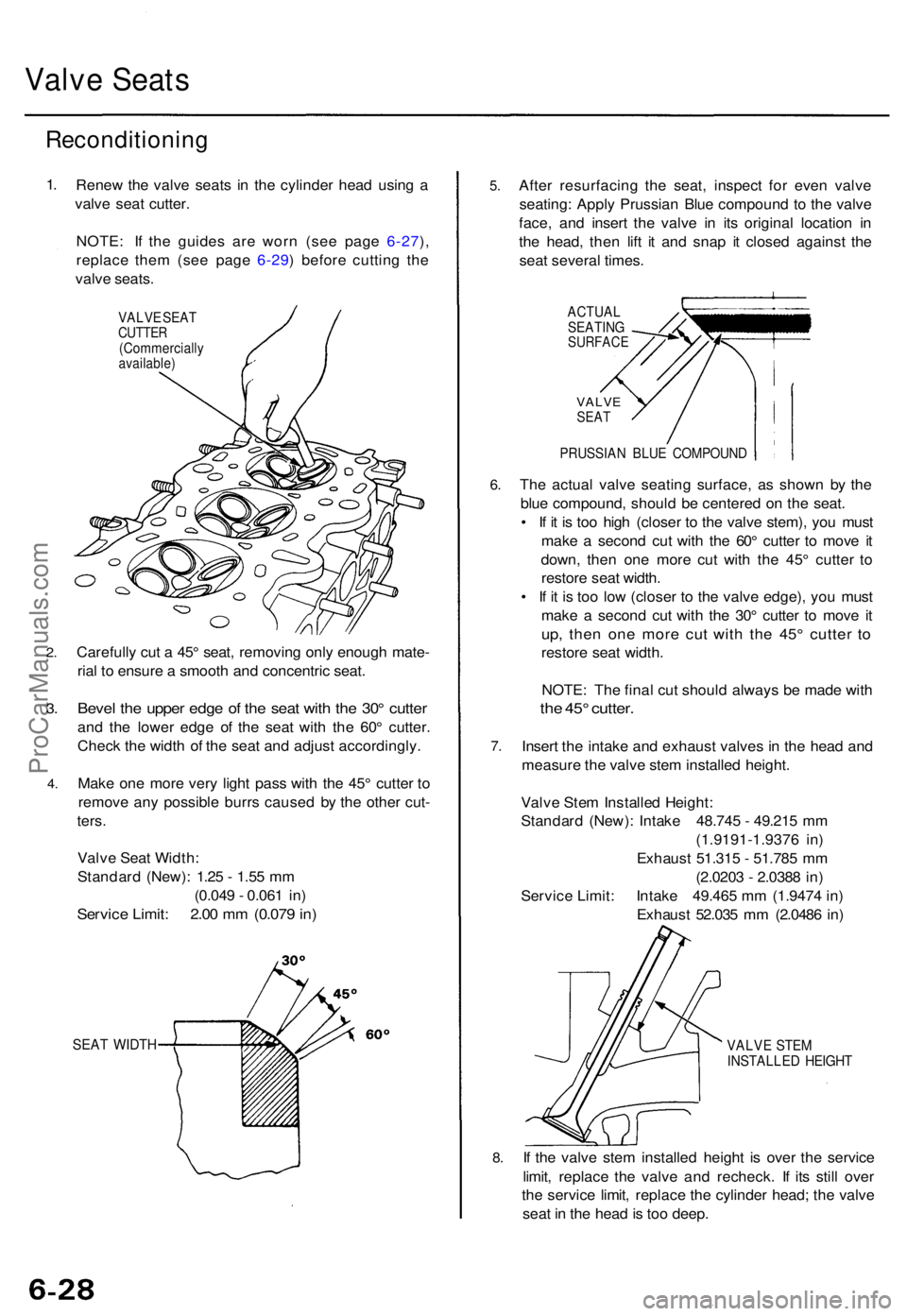
VALV E SEA TCUTTE R(Commerciall yavailable)
Carefully cu t a 45 ° seat , removin g onl y enoug h mate -
ria l t o ensur e a smoot h an d concentri c seat .
Beve l th e uppe r edg e o f th e sea t wit h th e 30 ° cutte r
and th e lowe r edg e o f th e sea t wit h th e 60 ° cutter .
Chec k th e widt h o f th e sea t an d adjus t accordingly .
Mak e on e mor e ver y ligh t pas s wit h th e 45 ° cutte r t o
remov e an y possibl e burr s cause d b y th e othe r cut -
ters .
Valv e Sea t Width :
Standar d (New) : 1.2 5 - 1.5 5 m m
(0.04 9 - 0.06 1 in )
Servic e Limit : 2.0 0 m m (0.07 9 in )
SEA T WIDT H
5.
6.
7 .
8.
Afte r resurfacin g th e seat , inspec t fo r eve n valv e
seating : Appl y Prussia n Blu e compoun d t o th e valv e
face , an d inser t th e valv e i n it s origina l locatio n i n
th e head , the n lif t i t an d sna p i t close d agains t th e
sea t severa l times .
ACTUA L
SEATIN G
SURFAC E
VALVESEAT
PRUSSIA N BLU E COMPOUN D
The actua l valv e seatin g surface , a s show n b y th e
blu e compound , shoul d b e centere d o n th e seat .
• I f i t i s to o hig h (close r t o th e valv e stem) , yo u mus t
mak e a secon d cu t wit h th e 60 ° cutte r t o mov e i t
down , the n on e mor e cu t wit h th e 45 ° cutte r t o
restor e sea t width .
• I f i t i s to o lo w (close r t o th e valv e edge) , yo u mus t
mak e a secon d cu t wit h th e 30 ° cutte r t o mov e i t
up , the n on e mor e cu t wit h th e 45 ° cutte r t o
restor e sea t width .
NOTE : Th e fina l cu t shoul d alway s b e mad e wit h
the 45 ° cutter .
Insert th e intak e an d exhaus t valve s i n th e hea d an d
measur e th e valv e ste m installe d height .
Valv e Ste m Installe d Height :
Standar d (New) : Intak e 48.74 5 - 49.21 5 m m
(1.9191-1.937 6 in )
Exhaus t 51.31 5 - 51.78 5 m m
(2.020 3 - 2.038 8 in )
Servic e Limit : Intak e 49.46 5 m m (1.947 4 in )
Exhaus t 52.03 5 m m (2.048 6 in )
VALV E STE M
INSTALLE D HEIGH T
If th e valv e ste m installe d heigh t i s ove r th e servic e
limit , replac e th e valv e an d recheck . I f it s stil l ove r
th e servic e limit , replac e th e cylinde r head ; th e valv e
sea t i n th e hea d is to o deep .
ProCarManuals.com
Page 765 of 1771
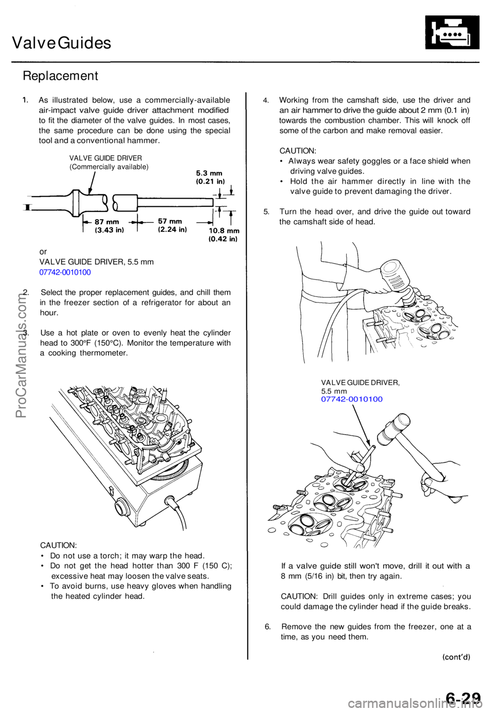
Valve Guide s
Replacemen t
I
As illustrate d below , us e a commercially-availabl e
air-impact valv e guid e drive r attachmen t modifie d
to fi t th e diamete r o f th e valv e guides . I n mos t cases ,
th e sam e procedur e ca n b e don e usin g th e specia l
tool an d a conventiona l hammer .
VALVE GUID E DRIVE R(Commerciall y available )
or
VALV E GUID E DRIVER , 5. 5 m m
07742-001010 0
2 . Selec t th e prope r replacemen t guides , an d chil l the m
i n th e freeze r sectio n o f a refrigerato r fo r abou t a n
hour .
3. Us e a ho t plat e o r ove n t o evenl y hea t th e cylinde r
hea d t o 300° F (150°C) . Monito r th e temperatur e wit h
a cookin g thermometer .
CAUTION :
• D o no t us e a torch ; i t ma y war p th e head .
• D o no t ge t th e hea d hotte r tha n 30 0 F (15 0 C) ;
excessiv e hea t ma y loose n th e valv e seats .
• T o avoi d burns , us e heav y glove s whe n handlin g
th e heate d cylinde r head .
4.
5.
Workin g fro m th e camshaf t side , us e th e drive r an d
an ai r hamme r t o driv e th e guid e abou t 2 m m (0. 1 in )
towards the combustio n chamber . Thi s wil l knoc k of f
som e o f th e carbo n an d mak e remova l easier .
CAUTION :
• Alway s wea r safet y goggle s o r a fac e shiel d whe n
drivin g valv e guides .
• Hol d th e ai r hamme r directl y i n lin e wit h th e
valv e guid e t o preven t damagin g th e driver .
Tur n th e hea d over , an d driv e th e guid e ou t towar d
th e camshaf t sid e o f head .
VALV E GUID E DRIVER ,5.5 m m07742-001010 0
If a valv e guid e stil l won' t move , dril l i t ou t wit h a
8 m m (5/1 6 in ) bit , the n tr y again .
CAUTION : Dril l guide s onl y i n extrem e cases ; yo u
coul d damag e th e cylinde r hea d if th e guid e breaks .
6 . Remov e th e ne w guide s fro m th e freezer , on e a t a
time , a s yo u nee d them .
ProCarManuals.com
Page 766 of 1771
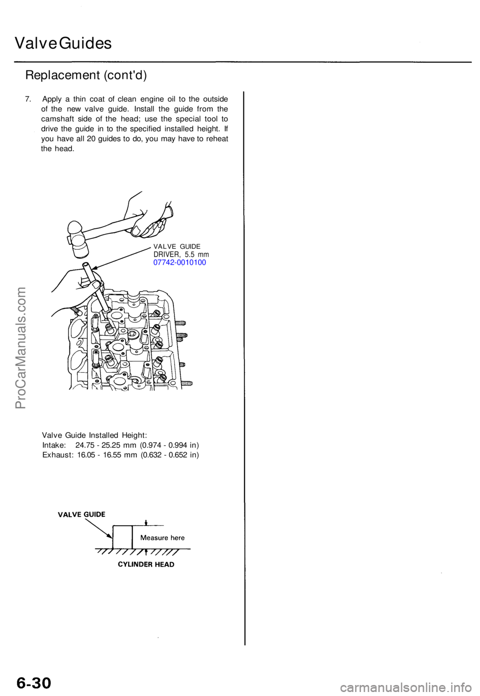
Valve Guide s
Replacemen t (cont'd )
7. Appl y a thi n coa t o f clea n engin e oi l t o th e outsid e
of th e ne w valv e guide . Instal l th e guid e fro m th e
camshaf t sid e o f th e head ; us e th e specia l too l t o
driv e th e guid e i n t o th e specifie d installe d height . I f
yo u hav e al l 2 0 guide s t o do , yo u ma y hav e to rehea t
th e head .
VALV E GUID EDRIVER , 5. 5 m m07742-001010 0
Valve Guid e Installe d Height :
Intake : 24.7 5 - 25.2 5 m m (0.97 4 - 0.99 4 in )
Exhaust : 16.0 5 - 16.5 5 m m (0.63 2 - 0.65 2 in )
ProCarManuals.com
Page 767 of 1771
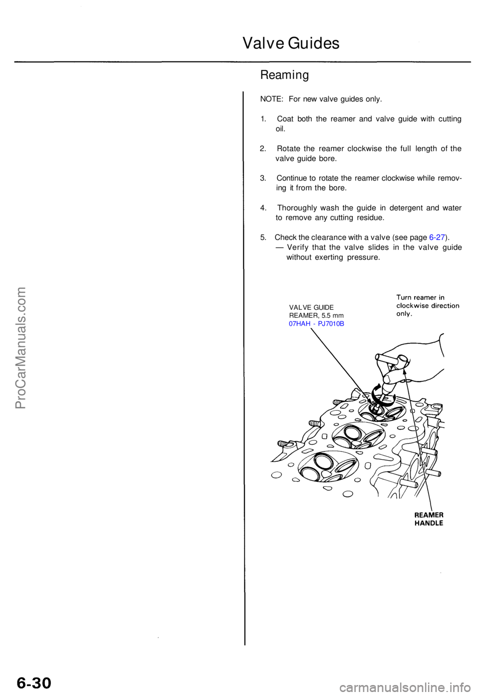
Valve Guide s
Reamin g
NOTE: Fo r ne w valv e guide s only .
1 . Coa t bot h th e reame r an d valv e guid e wit h cuttin g
oil.
2. Rotat e th e reame r clockwis e th e ful l lengt h o f th e
valv e guid e bore .
3 . Continu e t o rotat e th e reame r clockwis e whil e remov -
in g i t fro m th e bore .
4 . Thoroughl y was h th e guid e i n detergen t an d wate r
t o remov e an y cuttin g residue .
5 . Chec k th e clearanc e wit h a valv e (se e pag e 6-27 ).
— Verif y tha t th e valv e slide s i n th e valv e guid e
withou t exertin g pressure .
VALVE GUID E
REAMER , 5. 5 m m
07HA H - PJ7010 B
ProCarManuals.com
Page 768 of 1771
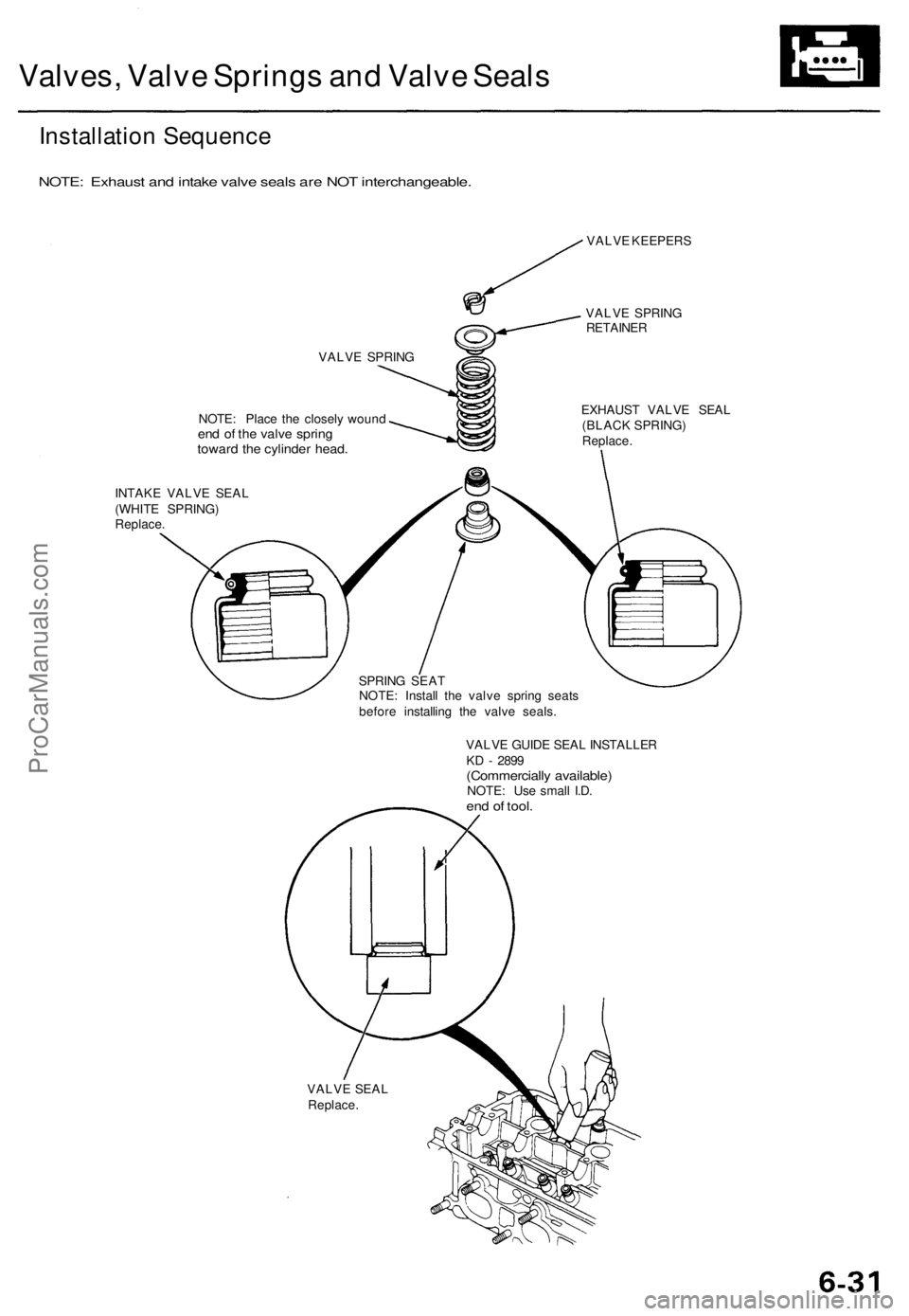
Valves, Valve Springs and Valve Seals
Installation Sequence
NOTE: Exhaust and intake valve seals are NOT interchangeable.
VALVE SPRING
NOTE: Place the closely wound
end of the valve spring
toward the cylinder head.
VALVE KEEPERS
VALVE SPRING
RETAINER
EXHAUST VALVE SEAL
(BLACK SPRING)
Replace.
INTAKE VALVE SEAL
(WHITE SPRING)
Replace.
SPRING SEAT
NOTE: Install the valve spring seats
before installing the valve seals.
VALVE GUIDE SEAL INSTALLER
KD - 2899
(Commercially available)
NOTE: Use small I.D.
end of tool.
VALVE SEAL
Replace.ProCarManuals.com
Page 769 of 1771
Valves, Valv e Spring s an d
Valv e Seal s
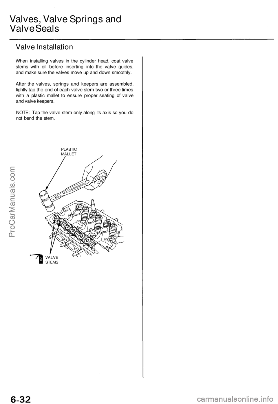
Valv e Installatio n
When installin g valve s i n th e cylinde r head , coa t valv e
stem s wit h oi l befor e insertin g int o th e valv e guides ,
an d mak e sur e th e valve s mov e u p an d dow n smoothly .
Afte r th e valves , spring s an d keeper s ar e assembled ,
lightly ta p th e en d o f eac h valv e ste m tw o o r thre e time s
with a plasti c malle t t o ensur e prope r seatin g o f valv e
an d valv e keepers .
NOTE : Ta p th e valv e ste m onl y alon g it s axi s s o yo u d o
no t ben d th e stem .
PLASTI CMALLET
VALVESTEMS
ProCarManuals.com
Page 770 of 1771
Camshaft/Rocker Arms and
Camshaft Seal
Installation
CAUTION:
• Make sure that all rockers are in alignment with their
valves when torquing the rocker assembly bolts.
• Valve locknuts should be loosened and adjusting
screws backed off before installation.
• To prevent the rocker arm assembly from coming
apart, leave the camshaft holder bolts in the holes.
1. After wiping down the camshaft and journals in the
cylinder head, lubricate both surfaces and install the
camshaft.
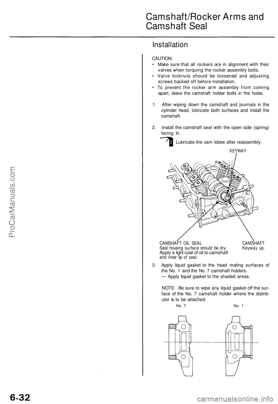
2. Install the camshaft seal with the open side (spring)
facing in.
Lubricate the cam lobes after reassembly.
KEYWAY
3.
CAMSHAFT OIL SEAL CAMSHAFT
Seal housing surface should be dry. Keyway up.
Apply a light coat of oil to camshaft
and inner lip of seal.
Apply liquid gasket to the head mating surfaces of
the No. 1 and the No. 7 camshaft holders.
— Apply liquid gasket to the shaded areas.
NOTE: Be sure to wipe any liquid gasket off the sur-
face of the No. 7 camshaft holder where the distrib-
utor is to be attached.
No. 7 No. 1ProCarManuals.com