ACURA TL 1995 Service Repair Manual
Manufacturer: ACURA, Model Year: 1995, Model line: TL, Model: ACURA TL 1995Pages: 1771, PDF Size: 62.49 MB
Page 771 of 1771
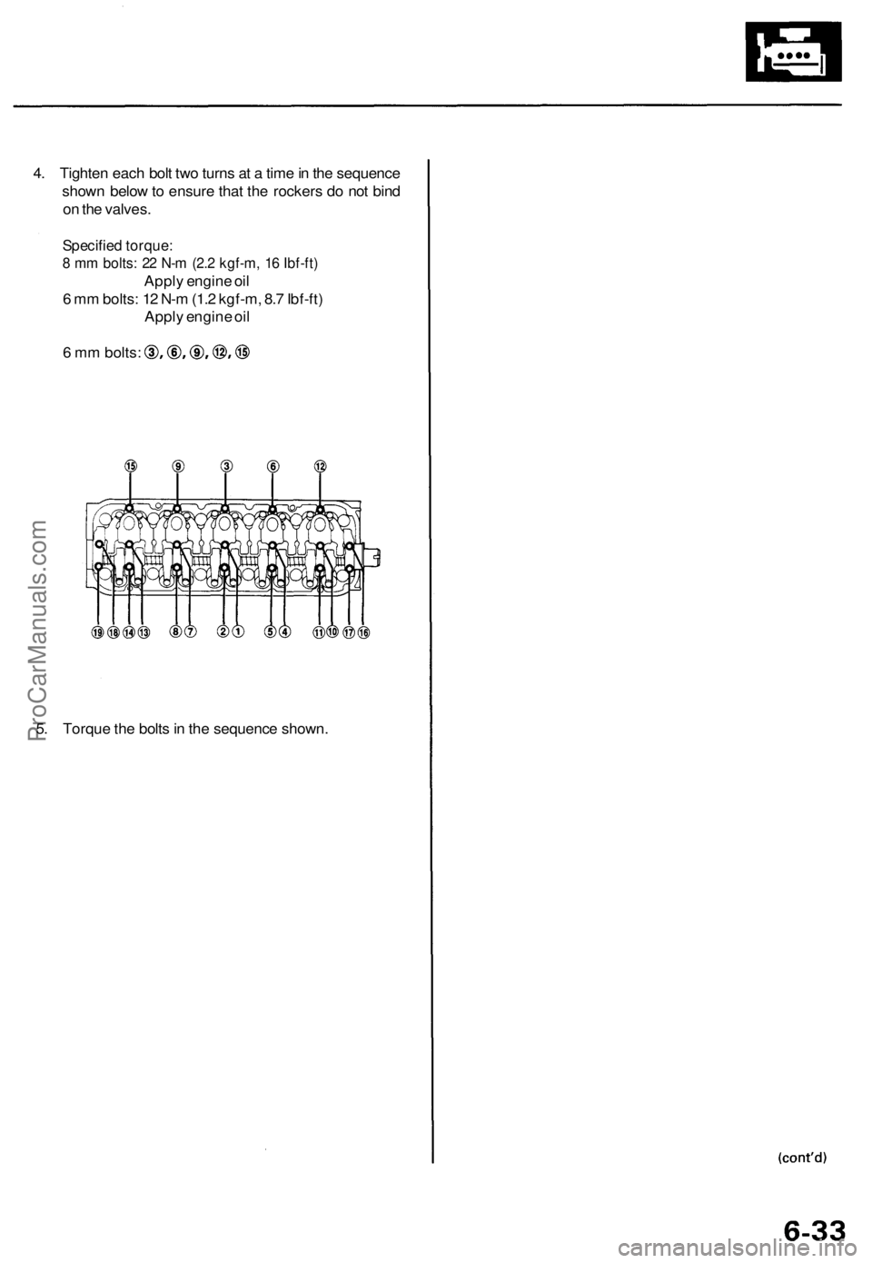
4. Tighten each bolt two turns at a time in the sequence
shown below to ensure that the rockers do not bind
on the valves.
Specified torque:
8 mm bolts: 22 N-m (2.2 kgf-m, 16 Ibf-ft)
Apply engine oil
6 mm bolts: 12 N-m (1.2 kgf-m, 8.7 Ibf-ft)
Apply engine oil
6 mm bolts:
5. Torque the bolts in the sequence shown.ProCarManuals.com
Page 772 of 1771
Cylinder Hea d
Installatio n
Install th e cylinde r hea d in th e revers e orde r o f removal :
NOTE:
Alway s us e a ne w cylinde r hea d gasket .
Cylinde r hea d an d cylinde r bloc k surfac e mus t b e clean .
Tur n th e camshaf t s o th e keywa y i n facin g up .
Tur n th e crankshaft so th e No . 1 pisto n is a t TD C (se e
pag e 6-11 ).
Clea n th e oi l contro l orific e befor e installing .
D o no t us e th e uppe r cove r an d lowe r cove r fo r stor -
in g remove d item .
• Clea n th e uppe r cove r an d lowe r cove r befor e instal -
lation.
1. Alig n th e cylinde r hea d dowe l pins .
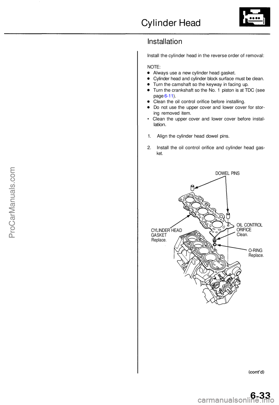
2 . Instal l th e oi l contro l orific e an d cylinde r hea d gas -
ket.
DOWE L PIN S
CYLINDE R HEA D
GASKE TReplace .
OIL CONTRO L
ORIFIC E
Clean .
O-RIN GReplace .
ProCarManuals.com
Page 773 of 1771
Cylinder Hea d
Installatio n (cont'd )
3. Tur n th e camshaf t unti l it s keywa y i s facin g u p (No . 1
pisto n TDC) .
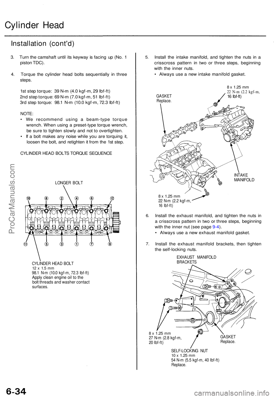
4 . Torqu e th e cylinde r hea d bolt s sequentiall y i n thre e
steps .
1s t ste p torque : 3 9 N- m (4. 0 kgf-m , 2 9 Ibf-ft )
2n d ste p torque : 6 9 N- m (7. 0 kgf-m , 5 1 Ibf-ft )
3r d ste p torque : 98. 1 N- m (10. 0 kgf-m , 72. 3 Ibf-ft )
NOTE :
• W e recommen d usin g a beam-typ e torqu e
wrench . Whe n usin g a preset-typ e torqu e wrench ,
b e sur e t o tighte n slowl y an d no t t o overtighten .
• I f a bol t make s an y nois e whil e yo u ar e torquin g it ,
loose n th e bolt , an d retighte n it fro m th e 1s t step .
CYLINDE R HEA D BOLT S TORQU E SEQUENC E
LONGER BOL T
CYLINDE R HEA D BOL T
12 x 1. 5 m m98. 1 N- m (10. 0 kgf-m , 72. 3 Ibf-ft )Apply clea n engin e oi l t o th ebol t thread s an d washe r contac tsurfaces .
5.
6.
7 .
Instal l th e intak e manifold , an d tighte n th e nut s i n a
crisscros s patter n i n tw o o r thre e steps , beginnin g
wit h th e inne r nuts .
• Alway s us e a ne w intak e manifol d gasket .
GASKE TReplace .
8 x 1.2 5 mm22 N- m (2. 2 kgf-m ,16 Ibf-ft )
INTAK EMANIFOL D
8 x 1.2 5 mm22 N- m (2. 2 kgf-m ,16 Ibf-ft )
Install th e exhaus t manifold , an d tighte n th e nut s i n
a crisscros s patter n in tw o o r thre e steps , beginnin g
wit h th e inne r nu t (se e pag e 9-4 ).
• Alway s us e a ne w exhaus t manifol d gasket .
Instal l th e exhaus t manifol d brackets , the n tighte n
th e self-lockin g nuts .
EXHAUS T MANIFOL DBRACKETS
8 x 1.2 5 mm27 N- m (2. 8 kgf-m ,
2 0 Ibf-ft )GASKE TReplace .
SELF-LOCKIN G NU T10 x 1.2 5 mm54 N- m (5. 5 kgf-m , 4 0 Ibf-ft )
Replace .
ProCarManuals.com
Page 774 of 1771
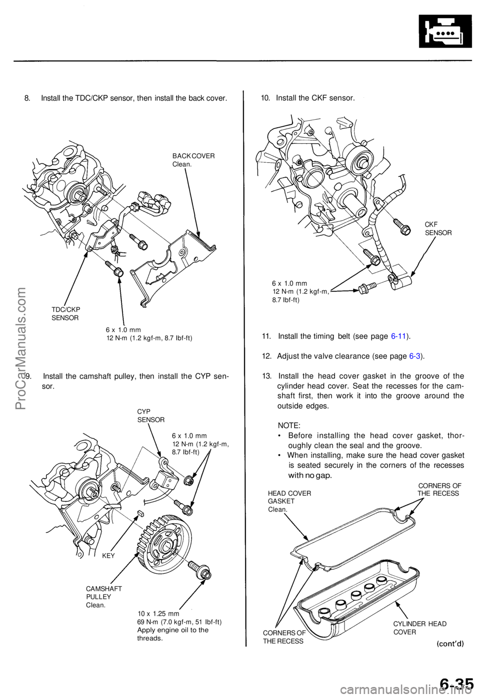
8. Instal l th e TDC/CK P sensor , the n instal l th e bac k cover .
BACK COVE R
Clean .
TDC/CK P
SENSO R
6 x 1. 0 m m12 N- m (1. 2 kgf-m , 8. 7 Ibf-ft )
9. Instal l th e camshaf t pulley , the n instal l th e CY P sen -
sor.
CY PSENSO R
6 x 1. 0 m m12 N- m (1. 2 kgf-m ,
8. 7 Ibf-ft )
CAMSHAF T
PULLEYClean.10 x 1.2 5 mm69 N- m (7. 0 kgf-m , 5 1 Ibf-ft )Apply engin e oi l t o th ethreads .
10. Instal l th e CK F sensor .
CKFSENSO R
6 x 1. 0 m m12 N- m (1. 2 kgf-m ,
8. 7 Ibf-ft )
11. Instal l th e timin g bel t (se e pag e 6-11 ).
12 . Adjus t th e valv e clearanc e (se e pag e 6-3 ).
13 . Instal l th e hea d cove r gaske t i n th e groov e o f th e
cylinde r hea d cover . Sea t th e recesse s fo r th e cam -
shaf t first , the n wor k i t int o th e groov e aroun d th e
outsid e edges .
NOTE:
• Befor e installin g th e hea d cove r gasket , thor -
oughl y clea n th e sea l an d th e groove .
• Whe n installing , mak e sur e th e hea d cove r gaske t
i s seate d securel y i n th e corner s o f th e recesse s
with n o gap .
CORNER S O F
HEA D COVE R TH E RECES S
GASKETClean.
CORNER S O F
TH E RECES S CYLINDE
R HEA DCOVE R
KEY
ProCarManuals.com
Page 775 of 1771
Cylinder Head
Installation (cont'd)
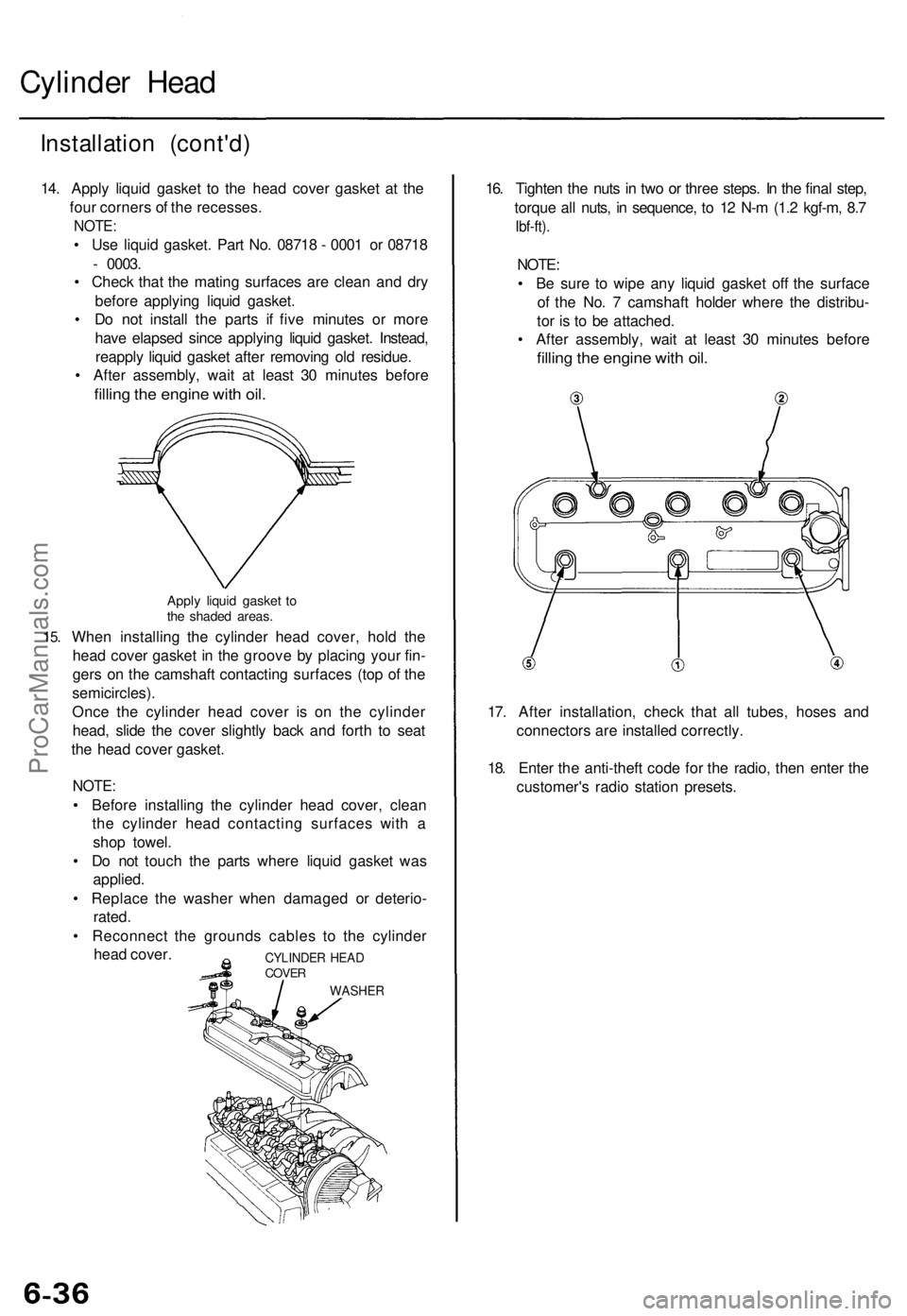
14. Apply liquid gasket to the head cover gasket at the
four corners of the recesses.
NOTE:
• Use liquid gasket. Part No. 08718 - 0001 or 08718
- 0003.
• Check that the mating surfaces are clean and dry
before applying liquid gasket.
• Do not install the parts if five minutes or more
have elapsed since applying liquid gasket. Instead,
reapply liquid gasket after removing old residue.
• After assembly, wait at least 30 minutes before
filling the engine with oil.
15.
Apply liquid gasket to
the shaded areas.
When installing the cylinder head cover, hold the
head cover gasket in the groove by placing your fin-
gers on the camshaft contacting surfaces (top of the
semicircles).
Once the cylinder head cover is on the cylinder
head, slide the cover slightly back and forth to seat
the head cover gasket.
NOTE:
• Before installing the cylinder head cover, clean
the cylinder head contacting surfaces with a
shop towel.
• Do not touch the parts where liquid gasket was
applied.
• Replace the washer when damaged or deterio-
rated.
• Reconnect the grounds cables to the cylinder
head cover.
16. Tighten the nuts in two or three steps. In the final step,
torque all nuts, in sequence, to 12 N-m (1.2 kgf-m, 8.7
Ibf-ft).
NOTE:
• Be sure to wipe any liquid gasket off the surface
of the No. 7 camshaft holder where the distribu-
tor is to be attached.
• After assembly, wait at least 30 minutes before
filling the engine with oil.
17. After installation, check that all tubes, hoses and
connectors are installed correctly.
18. Enter the anti-theft code for the radio, then enter the
customer's radio station presets.
CYLINDER HEAD
COVER
WASHERProCarManuals.com
Page 776 of 1771
Special Tool s
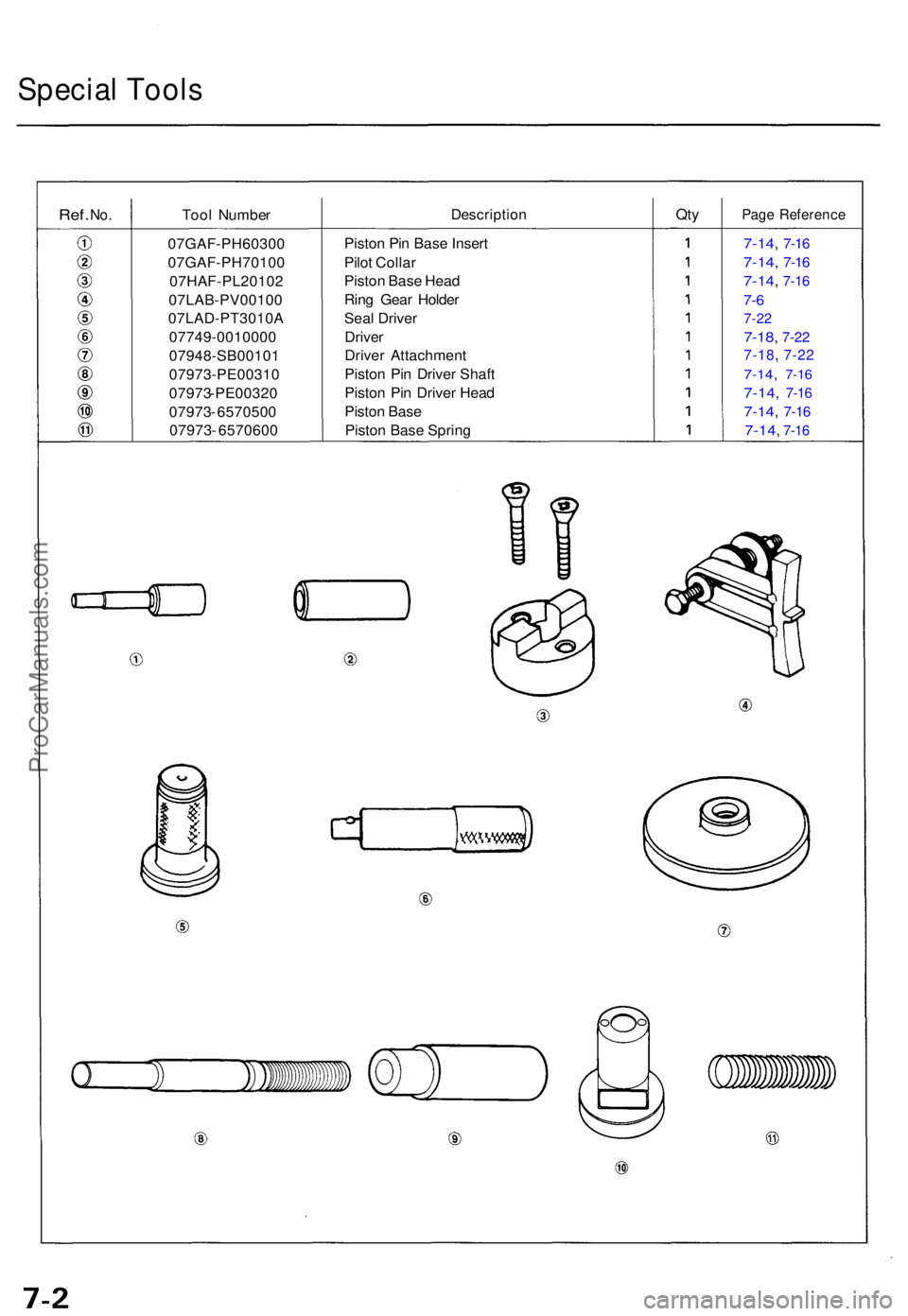
Ref. No.Too l Numbe rDescriptio nQtyPag e Referenc e
Piston Pi n Bas e Inser t
Pilo t Colla r
Pisto n Bas e Hea d
Rin g Gea r Holde r
Sea l Drive r
Drive r
Drive r Attachmen t
Pisto n Pi n Drive r Shaf t
Pisto n Pi n Drive r Hea d
Pisto n Bas e
Pisto n Bas e Sprin g7-14, 7-1 6
7-14 , 7-1 6
7-14 , 7-1 6
7-6
7-2 2
7-18 , 7-2 2
7-18 , 7-2 2
7-14 , 7-1 6
7-14 , 7-1 6
7-14 , 7-1 6
7-14 , 7-1 6
07GAF -PH60300
07GAF-PH70100 07HAF-PL20102
07LAB-PV00100
07LAD-PT3010A
07749-0010000
07948-SB00101
07973-PE00310
07973 - PE00320
07973 - 6570500
07973 - 6570600
ProCarManuals.com
Page 777 of 1771
Illustrated Inde x
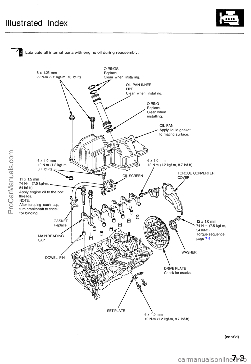
Lubricat e al l interna l part s wit h engin e oi l durin g reassembly .
8 x 1.2 5 mm22 N- m (2. 2 kgf-m , 1 6 Ibf-ft )
O-RING SReplace .Clean whe n installing .
OI L PA N INNE R
PIPEClea n whe n installing .
O-RIN G
Replace .Clean whe ninstalling .
DOWEL PI N
OIL PA NAppl y liqui d gaske tto matin g surface .
6 x 1. 0 m m12 N- m (1. 2 kgf-m , 8. 7 Ibf-ft )
TORQU E CONVERTE R
COVER
12 x 1. 0 m m74 N- m (7. 5 kgf-m ,
5 4 Ibf-ft )
Torqu e sequence ,page 7- 6
WASHE R
DRIVE PLAT E
Chec k fo r cracks .
SE T PLAT E
6 x 1. 0 m m12 N- m (1. 2 kgf-m , 8. 7 Ibf-ft )
6 x 1. 0 m m12 N- m (1. 2 kgf-m ,
8. 7 Ibf-ft )
11 x 1. 5 m m74 N- m (7. 5 kgf-m ,
5 4 Ibf-ft )
Apply engin e oi l t o th e bol tthreads .
NOTE :
Afte r torquin g eac h cap ,
turn crankshaf t t o chec kfor binding .
GASKE TReplace .
MAIN BEARIN GCAP
OIL SCREE N
ProCarManuals.com
Page 778 of 1771
Illustrated Inde x
(cont'd )
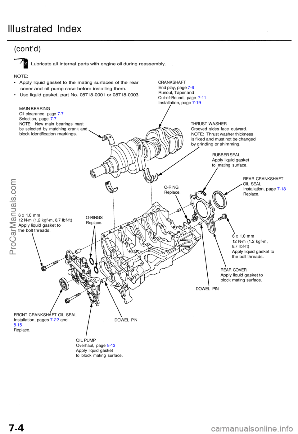
Lubricat e al l interna l part s wit h engin e oi l durin g reassembly .
NOTE:
• Appl y liqui d gaske t t o th e matin g surface s o f th e rea r
cove r an d oi l pum p cas e befor e installin g them .
• Us e liqui d gasket , par t No . 0871 8-000 1 o r 0871 8-0003 .
MAIN BEARIN GOil clearance , pag e 7- 7
Selection , pag e 7- 7
NOTE : Ne w mai n bearing s mus t
b e selecte d b y matchin g cran k an d
bloc k identificatio n markings .
CRANKSHAF TEnd play , pag e 7- 6Runout , Tape r an dOut-of-Round , pag e 7-1 1Installation , pag e 7-1 9
THRUS T WASHE R
Groove d side s fac e outward .
NOTE: Thrus t washe r thicknes sis fixe d an d mus t no t b e change dby grindin g o r shimming .
RUBBER SEA LApply liqui d gaske tto matin g surface .
REA R CRANKSHAF T
OI L SEA L
Installation , pag e 7-1 8Replace .
6 x 1. 0 m m12 N- m (1. 2 kgf-m , 8. 7 Ibf-ft )Apply liqui d gaske t t oth e bol t threads .
6 x 1. 0 m m12 N- m (1. 2 kgf-m ,
8. 7 Ibf-ft )
Apply liqui d gaske t t oth e bol t threads .
REAR COVE RApply liqui d gaske t t obloc k matin g surface .
DOWEL PI N
FRON T CRANKSHAF T OI L SEA L
Installation , page s 7-2 2 an d8-1 5Replace .
DOWEL PI N
OIL PUM POverhaul , pag e 8-1 3Appl y liqui d gaske tto bloc k matin g surface . O-RIN
G
Replace .
O-RINGS
Replace .
ProCarManuals.com
Page 779 of 1771
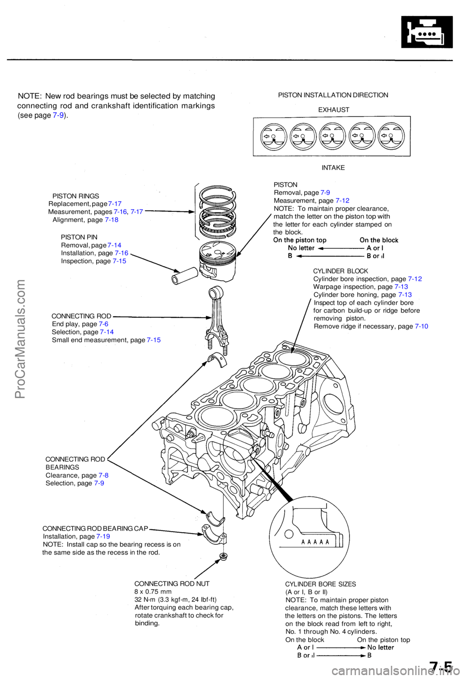
NOTE: Ne w ro d bearing s mus t b e selecte d b y matchin g
connectin g ro d an d crankshaf t identificatio n marking s
(see pag e 7-9 ).
PISTO N INSTALLATIO N DIRECTIO N
EXHAUST
PISTON RING S
Replacement , pag e 7-1 7
Measurement , page s 7-16 , 7-1 7
Alignment , pag e 7-1 8
PISTO N PI N
Removal , pag e 7-1 4
Installation , pag e 7-1 6
Inspection , pag e 7-1 5
INTAK E
PISTON
Removal , pag e 7- 9
Measurement , pag e 7-1 2
NOTE : T o maintai n prope r clearance ,
match th e lette r o n th e pisto n to p wit hthe lette r fo r eac h cylinde r stampe d o n
th e block .
CONNECTIN G RO D
En d play , pag e 7- 6
Selection , pag e 7-1 4
Smal l en d measurement , pag e 7-1 5
CYLINDE R BLOC KCylinde r bor e inspection , pag e 7-1 2
Warpag e inspection , pag e 7-1 3
Cylinde r bor e honing , pag e 7-1 3
Inspec t to p o f eac h cylinde r bor e
fo r carbo n build-u p o r ridg e befor e
removin g piston .
Remov e ridg e if necessary , pag e 7-1 0
CONNECTIN G RO D
BEARING SClearance , pag e 7- 8
Selection , pag e 7-9
CONNECTIN G RO D BEARIN G CA P
Installation , pag e 7-1 9
NOTE : Instal l ca p s o th e bearin g reces s is o n
th e sam e sid e a s th e reces s in th e rod .
CONNECTIN G RO D NU T
8 x 0.7 5 mm32 N- m (3. 3 kgf-m , 2 4 Ibf-ft )After torquin g eac h bearin g cap ,
rotat e crankshaf t t o chec k fo r
binding .
CYLINDE R BOR E SIZE S(A o r I , B or Il )NOTE : T o maintai n prope r pisto n
clearance , matc h thes e letter s wit h
th e letter s o n th e pistons . Th e letter s
o n th e bloc k rea d fro m lef t t o right ,
No . 1 throug h No . 4 cylinders .
O n th e bloc k O n th e pisto n to p
ProCarManuals.com
Page 780 of 1771
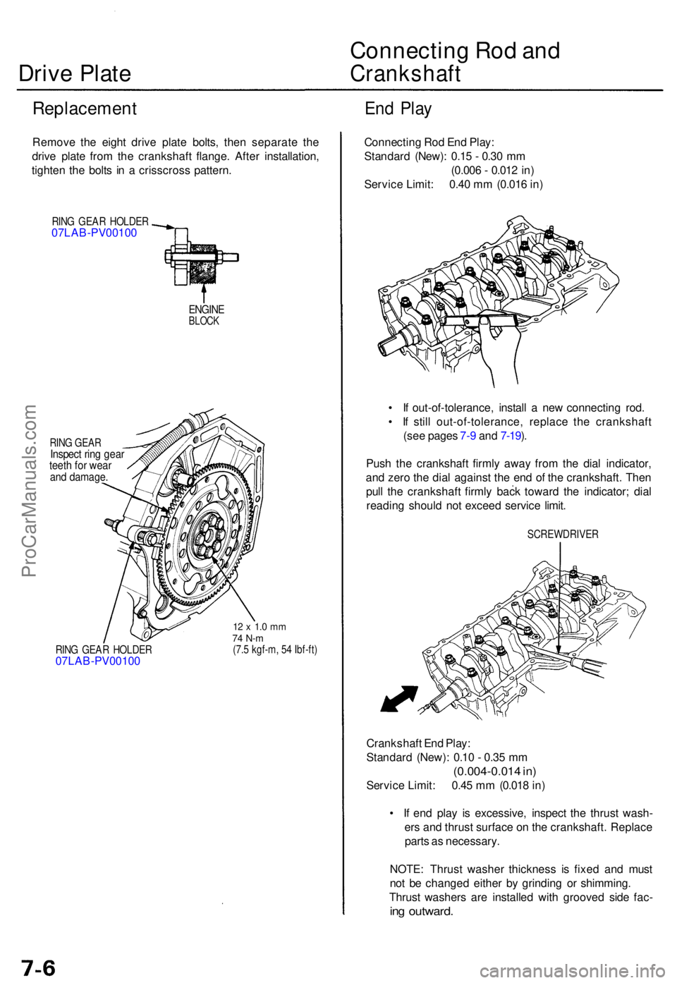
Drive Plat e Connectin
g Ro d an dCrankshaf t
Replacemen tEnd Pla y
Remov e th e eigh t driv e plat e bolts , the n separat e th e
driv e plat e fro m th e crankshaf t flange . Afte r installation ,
tighte n th e bolt s i n a crisscros s pattern .
RING GEA R HOLDE R07LAB-PV00100
ENGINEBLOCK
RING GEA RInspec t rin g gea rteeth fo r wea rand damage .
RING GEA R HOLDE R07LAB-PV0010 0
12 x 1. 0 m m74 N- m(7.5 kgf-m , 5 4 Ibf-ft )
Connectin g Ro d En d Play :
Standar d (New) : 0.1 5 - 0.3 0 m m
(0.00 6 - 0.01 2 in )
Servic e Limit : 0.4 0 m m (0.01 6 in )
• I f out-of-tolerance , instal l a ne w connectin g rod .
• I f stil l out-of-tolerance , replac e th e crankshaf t
(se e page s 7- 9 an d 7-19 ).
Pus h th e crankshaf t firml y awa y fro m th e dia l indicator ,
an d zer o th e dia l agains t th e en d o f th e crankshaft . The n
pul l th e crankshaf t firml y bac k towar d th e indicator ; dia l
readin g shoul d no t excee d servic e limit .
SCREWDRIVE R
Crankshaft En d Play :
Standar d (New) : 0.1 0 - 0.3 5 m m
(0.004-0.01 4 in )
Servic e Limit : 0.4 5 m m (0.01 8 in )
• I f en d pla y i s excessive , inspec t th e thrus t wash -
er s an d thrus t surfac e o n th e crankshaft . Replac e
part s a s necessary .
NOTE : Thrus t washe r thicknes s i s fixe d an d mus t
no t b e change d eithe r b y grindin g o r shimming .
Thrus t washer s ar e installe d wit h groove d sid e fac -
ing outward .
ProCarManuals.com