ACURA TL 1995 Service Repair Manual
Manufacturer: ACURA, Model Year: 1995, Model line: TL, Model: ACURA TL 1995Pages: 1771, PDF Size: 62.49 MB
Page 741 of 1771
Crankshaft Pulle y an d Pulle y Bol t
Replacemen t
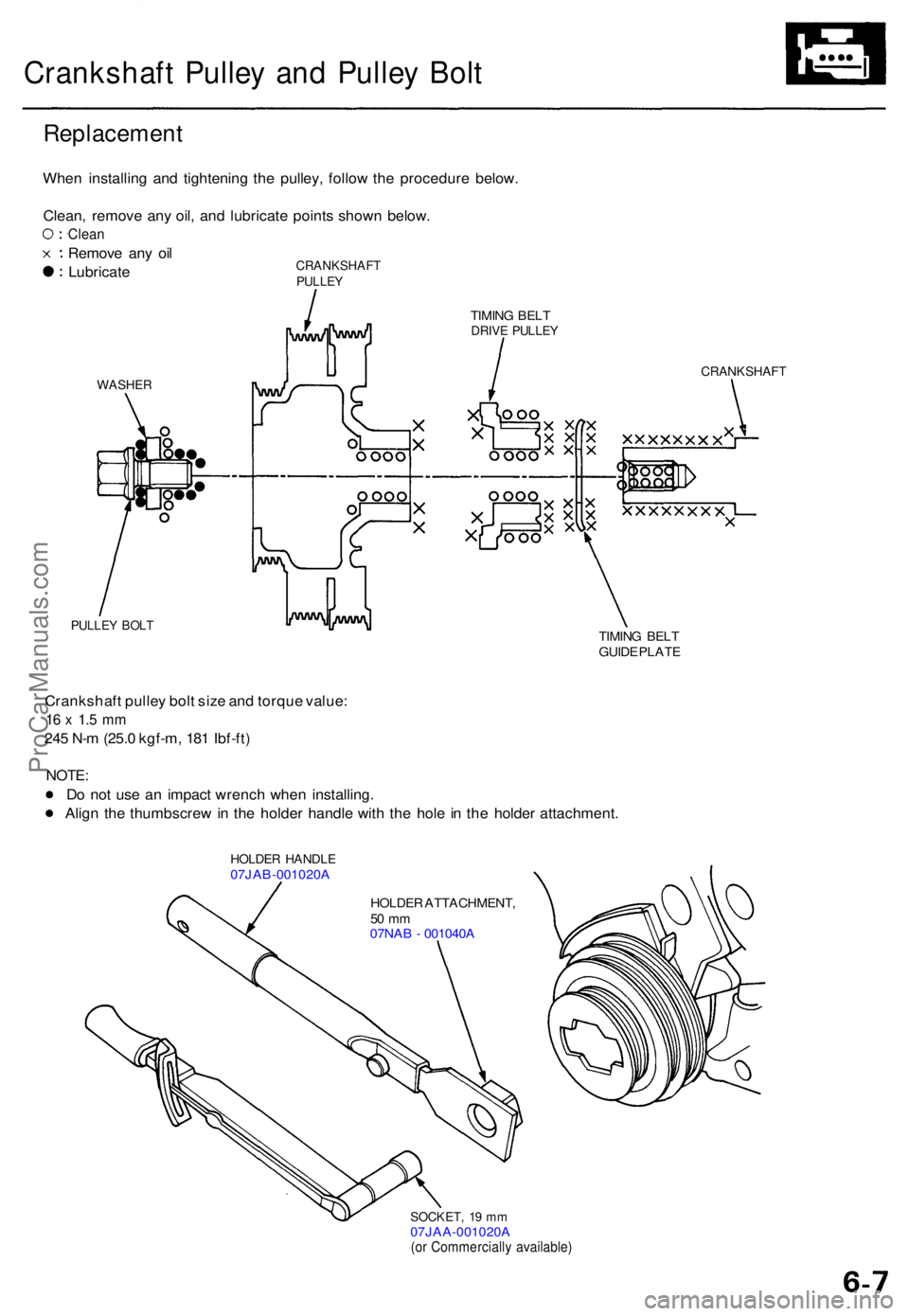
When installin g an d tightenin g th e pulley , follo w th e procedur e below .
Clean , remov e an y oil , an d lubricat e point s show n below .
Clean
Remov e an y oi l
Lubricat eCRANKSHAF TPULLEY
WASHE R
PULLEY BOL T
TIMIN G BEL TDRIV E PULLE Y
CRANKSHAF T
TIMING BEL T
GUID E PLAT E
Crankshaf t pulle y bol t siz e an d torqu e value :
16 x 1. 5 m m
245 N- m (25. 0 kgf-m , 18 1 Ibf-ft )
NOTE :
Do no t us e a n impac t wrenc h whe n installing .
Alig n th e thumbscre w in th e holde r handl e wit h th e hol e in th e holde r attachment .
HOLDER HANDL E07JAB-001020 A
HOLDER ATTACHMENT ,
50 m m07NA B - 001040 A
SOCKET , 1 9 m m07JAA-001020 A(or Commerciall y available )
ProCarManuals.com
Page 742 of 1771
Timing Bel t
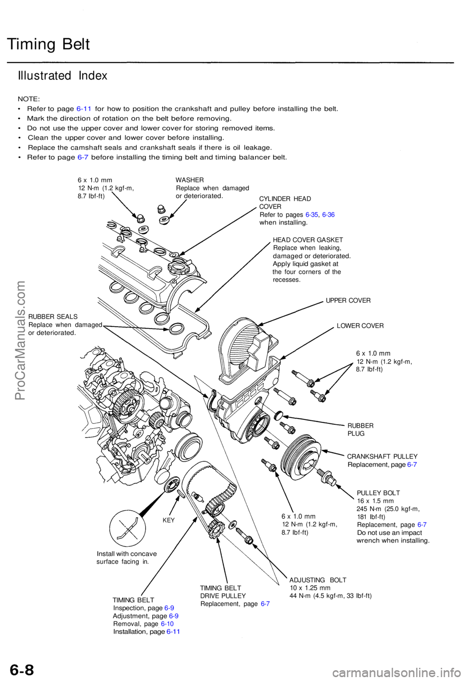
Illustrate d Inde x
NOTE :
• Refe r t o pag e 6-1 1 fo r ho w to positio n th e crankshaf t an d pulle y befor e installin g th e belt .
• Mar k th e directio n o f rotatio n o n th e bel t befor e removing .
• D o no t us e th e uppe r cove r an d lowe r cove r fo r storin g remove d items .
• Clea n th e uppe r cove r an d lowe r cove r befor e installing .
• Replac e th e camshaf t seal s an d crankshaf t seal s i f ther e i s oi l leakage .
• Refe r t o pag e 6- 7 befor e installin g th e timin g bel t an d timin g balance r belt .
6 x 1. 0 m m12 N- m (1. 2 kgf-m ,
8. 7 Ibf-ft ) WASHE
R
Replac e whe n damage dor deteriorated .CYLINDER HEA DCOVE RRefer t o page s 6-35 , 6-3 6whe n installing .
HEAD COVE R GASKE T
Replac e whe n leaking ,
damage d o r deteriorated .Apply liqui d gaske t a tth e fou r corner s o f th e
recesses .
RUBBE R SEAL S
Replac e whe n damage d
or deteriorated .
UPPER COVE R
LOWE R COVE R
6 x 1. 0 m m12 N- m (1. 2 kgf-m ,
8. 7 Ibf-ft )
RUBBE RPLUG
CRANKSHAF T PULLE Y
Replacement , pag e 6- 7
PULLE Y BOL T16 x 1. 5 m m245 N- m (25. 0 kgf-m ,
18 1 Ibf-ft )
Replacement , pag e 6- 7
Do no t us e a n impac twrench whe n installing .
Install wit h concav esurface facin g in .
TIMIN G BEL TInspection , pag e 6- 9Adjustment , pag e 6- 9Removal , pag e 6-1 0Installation , pag e 6-1 1
TIMIN G BEL TDRIV E PULLE Y
Replacement , pag e 6- 7 ADJUSTIN
G BOL T10 x 1.2 5 mm44 N- m (4. 5 kgf-m , 3 3 Ibf-ft )
KEY6 x 1. 0 m m12 N- m (1. 2 kgf-m ,
8. 7 Ibf-ft )
ProCarManuals.com
Page 743 of 1771
Inspection
1. Remov e th e cylinde r hea d cover .
• Refe r t o page s 6-35 , 6-3 6 whe n installing .
2 . Remov e th e uppe r cove r (se e pag e 6-8 ).
3 . Inspec t th e timin g bel t fo r crack s an d oi l o r coolan t
soaking .
NOTE:
• Replac e th e bel t i f oi l o r coolan t soaked .
• Remov e an y oi l o r solven t tha t get s o n th e belt .
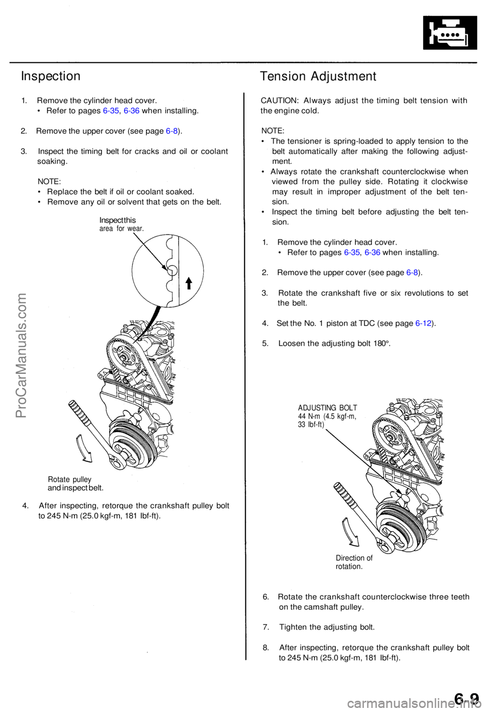
Inspec t thi s
are a fo r wear .
Tensio n Adjustmen t
Rotate pulle yand inspec t belt .
4 . Afte r inspecting , retorqu e th e crankshaf t pulle y bol t
t o 24 5 N- m (25. 0 kgf-m , 18 1 Ibf-ft) . CAUTION
: Alway s adjus t th e timin g bel t tensio n wit h
th e engin e cold .
NOTE :
• Th e tensione r i s spring-loade d t o appl y tensio n t o th e
bel t automaticall y afte r makin g th e followin g adjust -
ment .
• Alway s rotat e th e crankshaf t counterclockwis e whe n
viewe d fro m th e pulle y side . Rotatin g i t clockwis e
ma y resul t i n imprope r adjustmen t of the bel t ten -
sion .
• Inspec t th e timin g bel t befor e adjustin g th e bel t ten -
sion .
1 . Remov e th e cylinde r hea d cover .
• Refe r t o page s 6-35 , 6-3 6 whe n installing .
2 . Remov e th e uppe r cove r (se e pag e 6-8 ).
3 . Rotat e th e crankshaf t fiv e o r si x revolution s t o se t
th e belt .
4 . Se t th e No . 1 pisto n a t TD C (se e pag e 6-12 ).
5 . Loose n th e adjustin g bol t 180° .
ADJUSTIN G BOL T44 N- m (4. 5 kgf-m ,
3 3 Ibf-ft )
Directio n o frotation .
6. Rotat e th e crankshaf t counterclockwis e thre e teet h
o n th e camshaf t pulley .
7 . Tighte n th e adjustin g bolt .
8 . Afte r inspecting , retorqu e th e crankshaf t pulle y bol t
t o 24 5 N- m (25. 0 kgf-m , 18 1 Ibf-ft) .
ProCarManuals.com
Page 744 of 1771
Tinning Bel t
Remova l
NOTE:
2.
3.
Replac e th e timin g bel t a t 105,00 0 mile s (168,00 0 km )
accordin g t o th e maintenanc e schedul e (norma l con -
ditions/sever e conditions) .
I f th e vehicl e regularl y i s drive n i n on e o r mor e o f th e
followin g conditions , replac e th e timin g bel t a t 60,00 0
mile s (U.S.A. ) 100,00 0 k m (Canada) .
• I n ver y hig h temperature s (ove r 110°F , 43°C) .
• I n ver y lo w temperature s (unde r -20°F , -29°C) .
Tur n th e crankshaf t pulle y s o th e No . 1 pisto n i s a t
to p dea d cente r (TDC ) befor e removin g th e bel t (se e
page 6-12).
Inspec t th e wate r pum p (se e pag e 10-10 ).
Loose n th e adjustin g bolt , locknu t an d mountin g
bolt , the n remov e th e powe r steerin g (P/S ) pum p
bel t (se e pag e 5-4 ).
Loose n th e idle r pulle y cente r nu t an d adjustin g
bolt , the n remov e th e ai r conditionin g (A/ C com -
presso r bel t (se e pag e 5-5 ).
Loose n th e adjustin g nut , loc k bol t an d mountin g
bolt , the n remov e th e alternato r belt .
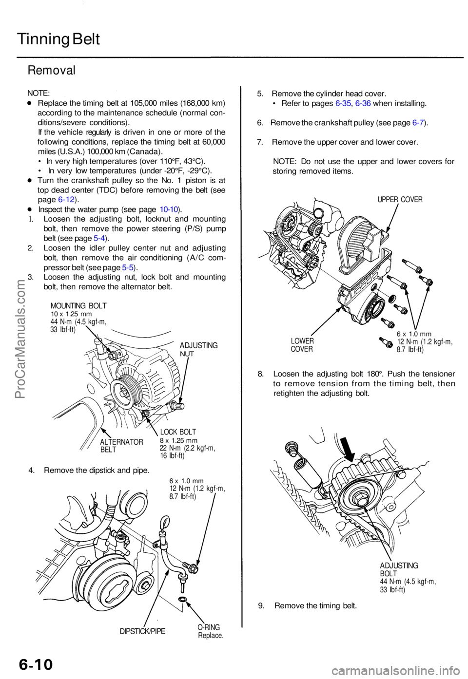
MOUNTIN G BOL T10 x 1.2 5 mm44 N- m (4. 5 kgf-m ,
3 3 Ibf-ft )
ADJUSTIN GNUT
ALTERNATO RBELT
4. Remov e th e dipstic k an d pipe .
LOCK BOL T8 x 1.2 5 mm22 N- m (2. 2 kgf-m ,
1 6 Ibf-ft )
6 x 1. 0 m m12 N- m (1. 2 kgf-m ,
8. 7 Ibf-ft )
DIPSTICK/PIP EO-RINGReplace .
5. Remov e th e cylinde r hea d cover .
• Refe r t o page s 6-35 , 6-3 6 whe n installing .
6 . Remov e th e crankshaf t pulle y (se e pag e 6-7 ).
7 . Remov e th e uppe r cove r an d lowe r cover .
NOTE : D o no t us e th e uppe r an d lowe r cover s fo r
storin g remove d items .
UPPER COVE R
LOWE R
COVE R
6 x 1. 0 m m12 N- m (1. 2 kgf-m ,
8. 7 Ibf-ft )
8. Loose n th e adjustin g bol t 180° . Pus h th e tensione r
to remov e tensio n fro m th e timin g belt , the n
retighte n th e adjustin g bolt .
ADJUSTIN GBOLT
4 4 N- m (4. 5 kgf-m ,
3 3 Ibf-ft )
9. Remov e th e timin g belt .
1.
ProCarManuals.com
Page 745 of 1771
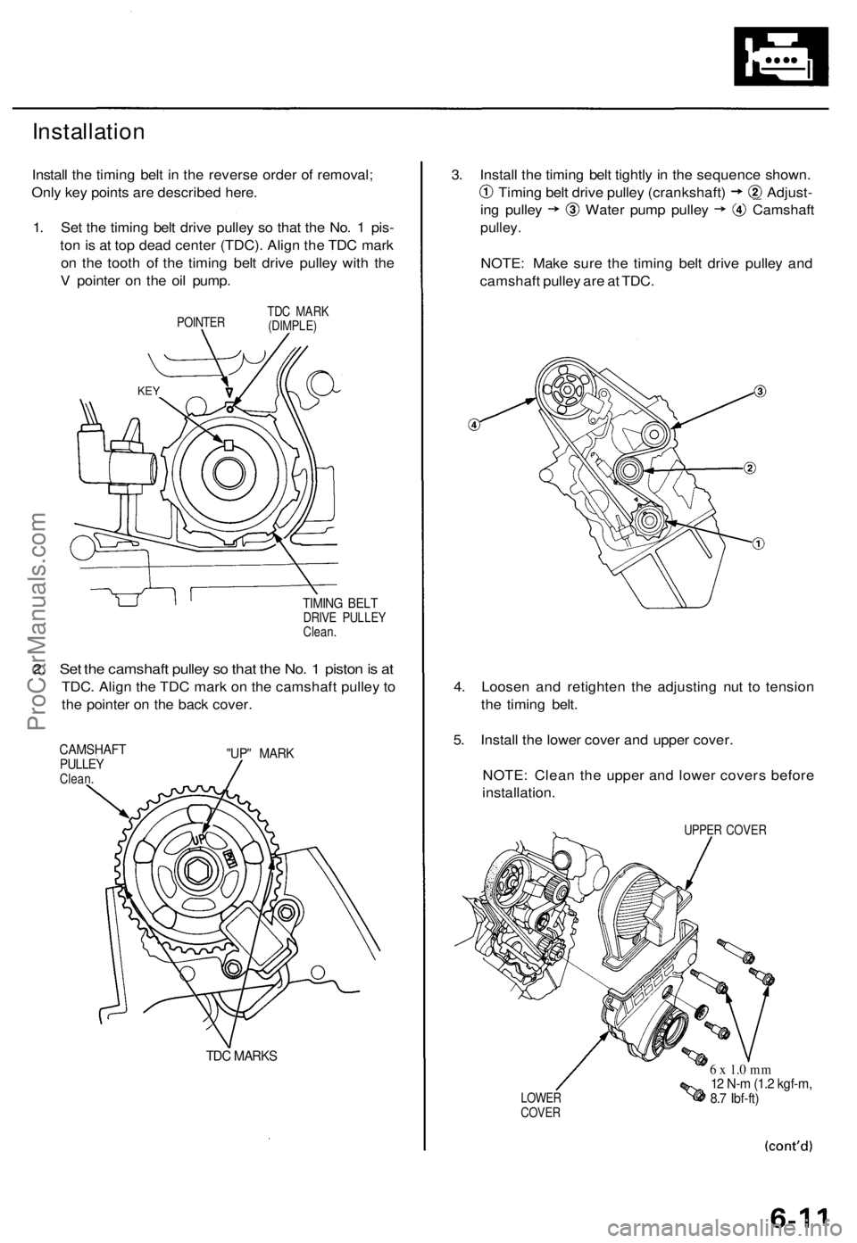
Installation
Install the timing belt in the reverse order of removal;
Only key points are described here.
1. Set the timing belt drive pulley so that the No. 1 pis-
ton is at top dead center (TDC). Align the TDC mark
on the tooth of the timing belt drive pulley with the
V pointer on the oil pump.
POINTER
TDC MARK
(DIMPLE)
TIMING BELT
DRIVE PULLEY
Clean.
2. Set the camshaft pulley so that the No. 1 piston is at
TDC. Align the TDC mark on the camshaft pulley to
the pointer on the back cover.
CAMSHAFT
PULLEY
Clean.
"UP" MARK
TDC MARKS
3. Install the timing belt tightly in the sequence shown.
Timing belt drive pulley (crankshaft) _ Adjust-
ing pulley Water pump pulley Camshaft
pulley.
NOTE: Make sure the timing belt drive pulley and
camshaft pulley are at TDC.
4. Loosen and retighten the adjusting nut to tension
the timing belt.
5. Install the lower cover and upper cover.
NOTE: Clean the upper and lower covers before
installation.
UPPER COVER
LOWER
COVER
6 x 1.0 mm
12 N-m (1.2 kgf-m,
8.7 Ibf-ft)
KEYProCarManuals.com
Page 746 of 1771
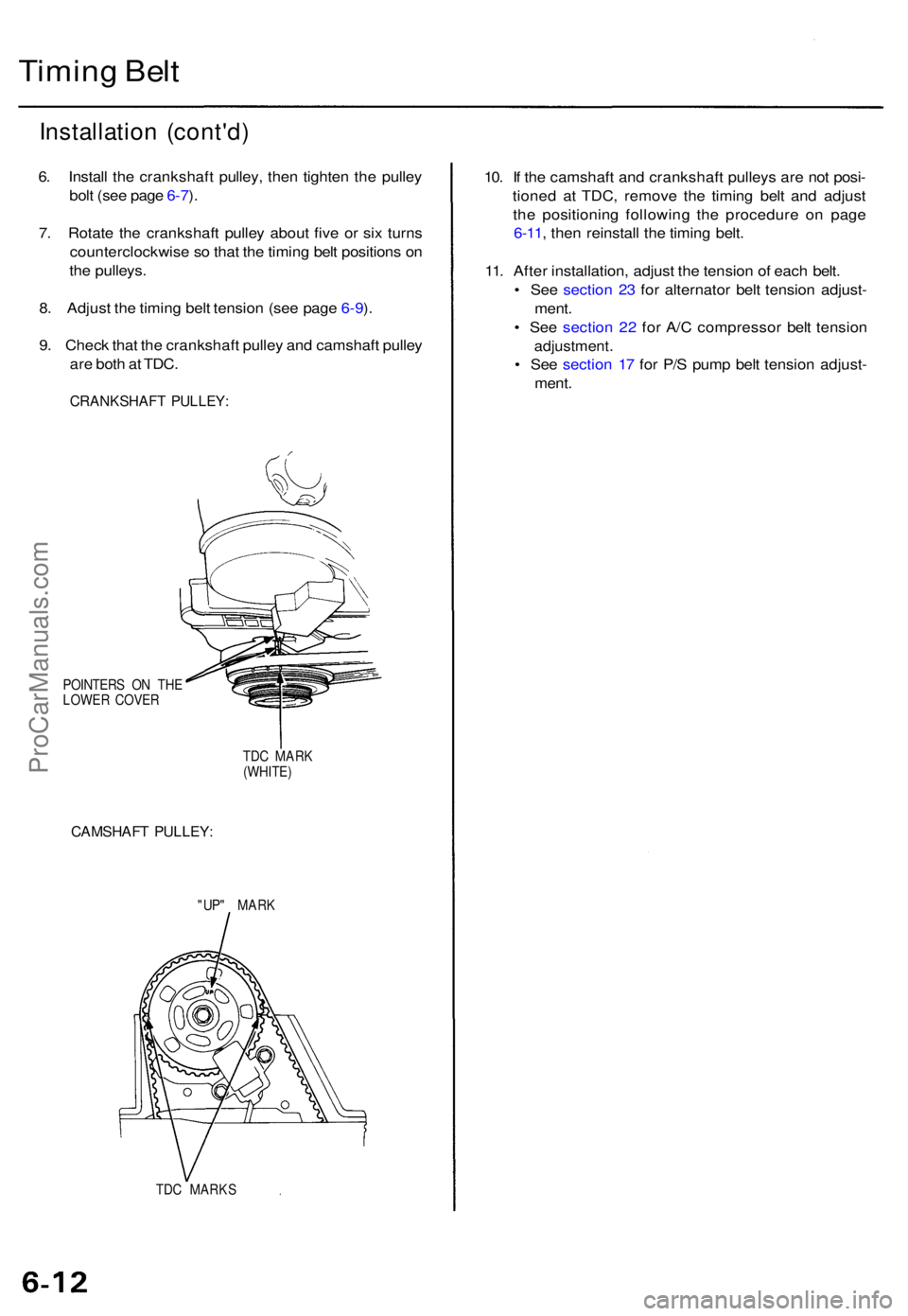
Timing Bel t
Installatio n (cont'd )
6. Instal l th e crankshaf t pulley , the n tighte n th e pulle y
bol t (se e pag e 6-7 ).
7 . Rotat e th e crankshaf t pulle y abou t fiv e o r si x turn s
counterclockwis e s o tha t th e timin g bel t position s o n
th e pulleys .
8 . Adjus t th e timin g bel t tensio n (se e pag e 6-9 ).
9 . Chec k tha t th e crankshaf t pulle y an d camshaf t pulle y
ar e bot h a t TDC .
CRANKSHAF T PULLEY :
POINTER S O N TH E
LOWE R COVE R
TDC MAR K
(WHITE )
CAMSHAF T PULLEY :
"UP" MAR K
TD C MARK S
10. I f th e camshaf t an d crankshaf t pulley s ar e no t posi -
tione d a t TDC , remov e th e timin g bel t an d adjus t
th e positionin g followin g th e procedur e o n pag e
6-11 , the n reinstal l th e timin g belt .
11 . Afte r installation , adjus t th e tensio n o f eac h belt .
• Se e sectio n 2 3 fo r alternato r bel t tensio n adjust -
ment .
• Se e sectio n 2 2 fo r A/ C compresso r bel t tensio n
adjustment .
• Se e sectio n 1 7 fo r P/ S pum p bel t tensio n adjust -
ment .
ProCarManuals.com
Page 747 of 1771
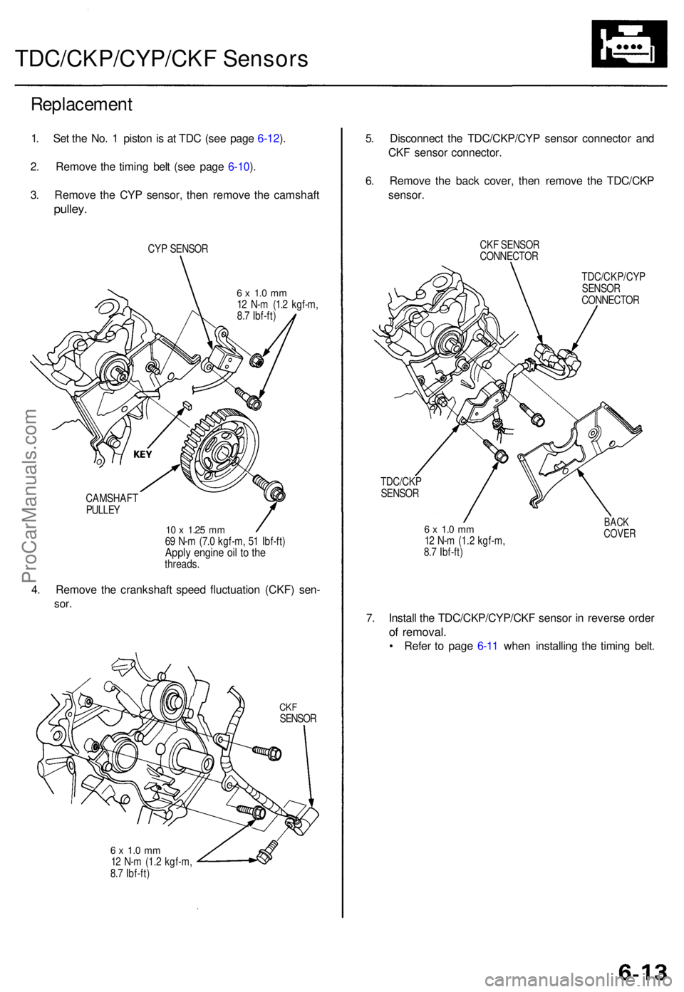
TDC/CKP/CYP/CKF Sensor s
Replacemen t
1. Se t th e No . 1 pisto n is a t TD C (se e pag e 6-12 ).
2 . Remov e th e timin g bel t (se e pag e 6-10 ).
3 . Remov e th e CY P sensor , the n remov e th e camshaf t
pulley.
CYP SENSO R
6 x 1. 0 m m12 N- m (1. 2 kgf-m ,
8. 7 Ibf-ft )
CAMSHAF T
PULLE Y
10 x 1.2 5 mm69 N- m (7. 0 kgf-m , 5 1 Ibf-ft )Apply engin e oi l t o th ethreads .
4. Remov e th e crankshaf t spee d fluctuatio n (CKF ) sen -
sor.
CKFSENSO R
6 x 1. 0 m m12 N- m (1. 2 kgf-m ,
8. 7 Ibf-ft )
5. Disconnec t th e TDC/CKP/CY P senso r connecto r an d
CK F senso r connector .
6 . Remov e th e bac k cover , the n remov e th e TDC/CK P
sensor .
CKF SENSO R
CONNECTO R
TDC/CKP/CY P
SENSO R
CONNECTO R
TDC/CK P
SENSO R
6 x 1. 0 m m12 N- m (1. 2 kgf-m ,
8. 7 Ibf-ft )
BACKCOVE R
7. Instal l th e TDC/CKP/CYP/CK F senso r i n revers e orde r
of removal .
• Refe r t o pag e 6-1 1 whe n installin g th e timin g belt .
ProCarManuals.com
Page 748 of 1771
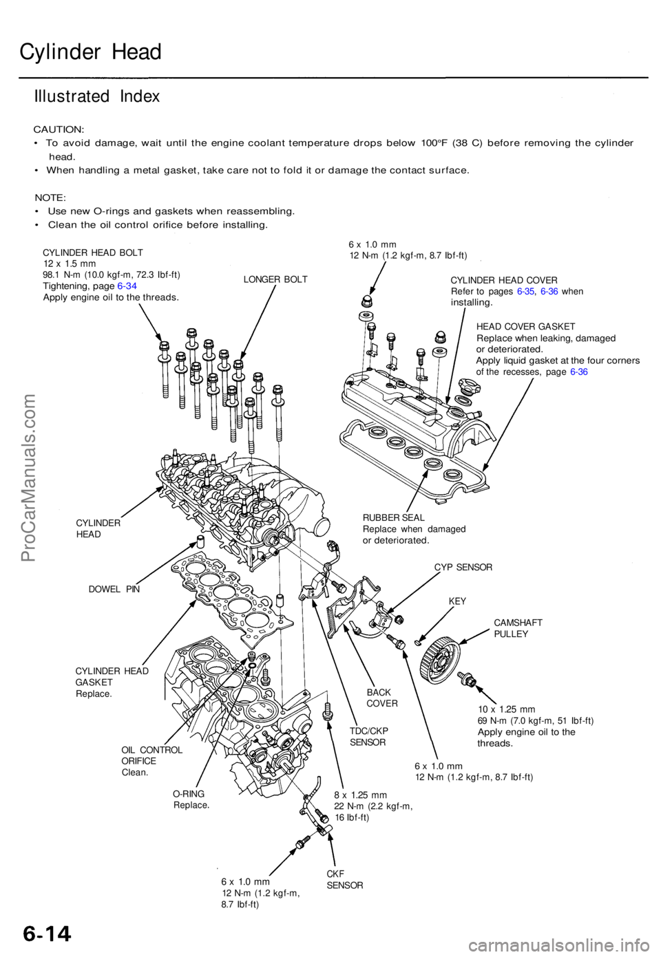
Cylinder Hea d
Illustrate d Inde x
CAUTION :
• T o avoi d damage , wai t unti l th e engin e coolan t temperatur e drop s belo w 100° F (3 8 C ) befor e removin g th e cylinde r
head.
• Whe n handlin g a meta l gasket , tak e car e no t t o fol d it o r damag e th e contac t surface .
NOTE:
• Us e ne w O-ring s an d gasket s whe n reassembling .
• Clea n th e oi l contro l orific e befor e installing .
CYLINDER HEA D BOL T12 x 1. 5 m m98. 1 N- m (10. 0 kgf-m , 72. 3 Ibf-ft )Tightening , pag e 6-3 4Appl y engin e oi l t o th e threads .
6 x 1. 0 m m12 N- m (1. 2 kgf-m , 8. 7 Ibf-ft )
LONGE R BOL T
CYLINDE R
HEA D
DOWE L PI N
CYLINDE R HEA D
GASKE T
Replace . CYLINDE
R HEA D COVE R
Refe r t o page s 6-35 , 6-3 6 whe n
installing .
HEAD COVE R GASKE TReplace whe n leaking , damage dor deteriorated .Apply liqui d gaske t a t th e fou r corner sof th e recesses , pag e 6-3 6
CAMSHAF T
PULLEY
OIL CONTRO L
ORIFIC E
Clean .
10 x 1.2 5 mm69 N- m (7. 0 kgf-m , 5 1 Ibf-ft )Apply engin e oi l t o th ethreads .
6 x 1. 0 m m12 N- m (1.2 kgf-m , 8. 7 Ibf-ft )
O-RIN G
Replac e
6 x 1. 0 m m12 N- m (1. 2 kgf-m ,
8. 7 Ibf-ft )
CKFSENSO R
8 x 1.2 5 mm22 N- m (2. 2 kgf-m ,
1 6 Ibf-ft )
TDC/CK
P
SENSO R
BACKCOVE R
CYP SENSO R
KEY
RUBBE R SEA L
Replac e whe n damage d
or deteriorated .
ProCarManuals.com
Page 749 of 1771
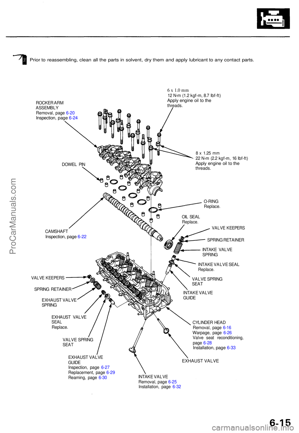
Prior t o reassembling , clea n al l th e part s in solvent , dr y the m an d appl y lubrican t t o an y contac t parts .
ROCKE R AR M
ASSEMBL Y
Removal , pag e 6-2 0
Inspection , pag e 6-2 4
6 x 1. 0 m m12 N- m (1. 2 kgf-m , 8. 7 Ibf-ft )Apply engin e oi l t o th ethreads .
DOWE L PI N
O-RING
Replace .
CAMSHAF TInspection, pag e 6-2 2
VALV E KEEPER S
SPRING RETAINE R
EXHAUS T VALV E
SPRIN G
EXHAUS T VALV E
SEALReplace .
VALVE SPRIN GSEAT
8 x 1.2 5 mm22 N- m (2. 2 kgf-m , 1 6 Ibf-ft )Apply engin e oi l t o th ethreads .
VALVE KEEPER S
SPRING RETAINE R
INTAK E VALV E
SPRIN G
INTAK E VALV E SEA L
Replace .
VALVE SPRIN G
SEA T
EXHAUS T VALV E
GUID E
Inspection , pag e 6-2 7
Replacement , pag e 6-2 9
Reaming , pag e 6-3 0 CYLINDE
R HEA D
Removal , pag e 6-1 6
Warpage , pag e 6-2 6
Valv e sea t reconditioning ,
pag e 6-2 8
Installation , pag e 6-3 3
EXHAUST VALVE
INTAK E VALV E
Removal , pag e 6-2 5
Installation , pag e 6-3 2OI
L SEA L
Replace .
INTAKE VALV E
GUID E
ProCarManuals.com
Page 750 of 1771
Cylinder Hea d
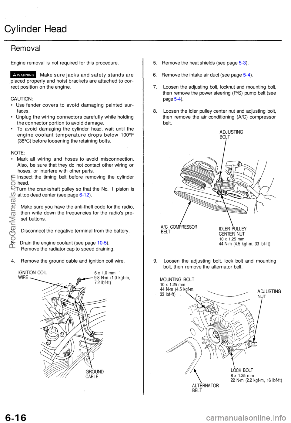
Remova l
Engine remova l i s no t require d fo r thi s procedure .
Mak e sur e jack s an d safet y stand s ar e
place d properl y an d hois t bracket s ar e attache d to cor -
rec t positio n o n th e engine .
CAUTION :
• Us e fende r cover s t o avoi d damagin g painte d sur -
faces .
• Unplu g th e wirin g connector s carefull y whil e holdin g
th e connecto r portio n to avoi d damage .
• T o avoi d damagin g th e cylinde r head , wai t unti l th e
engin e coolan t temperatur e drop s belo w 100° F
(38°C ) befor e loosenin g th e retainin g bolts .
NOTE :
• Mar k al l wirin g an d hose s t o avoi d misconnection .
Also , b e sur e tha t the y d o no t contac t othe r wirin g o r
hoses , o r interfer e wit h othe r parts .
• Inspec t th e timin g bel t befor e removin g th e cylinde r
head .
• Tur n th e crankshaf t pulle y s o tha t th e No . 1 pisto n i s
a t to p dea d cente r (se e pag e 6-12 ).
1 . Mak e sur e yo u hav e th e anti-thef t cod e fo r th e radio ,
the n writ e dow n th e frequencie s fo r th e radio' s pre -
se t buttons .
2 . Disconnec t th e negativ e termina l fro m th e battery .
3 . Drai n th e engin e coolan t (se e pag e 10-5 ).
Remov e th e radiato r cap to spee d draining .
4 . Remov e th e groun d cabl e an d ignitio n coi l wire .
IGNITIO N COI LWIRE6 x 1. 0 m m9.8 N- m (1. 0 kgf-m ,
7. 2 Ibf-ft )
GROUN DCABLE
5. Remov e th e hea t shield s (se e pag e 5-3 ).
6 . Remov e th e intak e ai r duc t (se e pag e 5-4 ).
7 . Loose n th e adjustin g bolt , locknu t an d mountin g bolt ,
the n remov e th e powe r steerin g (P/S ) pum p bel t (se e
page 5-4 ).
8 . Loose n th e idle r pulle y cente r nu t an d adjustin g bolt ,
the n remov e th e ai r conditionin g (A/C ) compresso r
belt .
ADJUSTIN GBOLT
A/ C COMPRESSO R
BELTIDLE R PULLE YCENTER NU T10 x 1.2 5 mm44 N- m (4. 5 kgf-m , 3 3 Ibf-ft )
9. Loose n th e adjustin g bolt , loc k bol t an d mountin g
bolt , the n remov e th e alternato r belt .
MOUNTIN G BOL T10 x 1.2 5 mm44 N- m (4. 5 kgf-m ,
3 3 Ibf-ft )ADJUSTIN GNUT
LOC K BOL T8 x 1.2 5 mm22 N- m (2. 2 kgf-m , 1 6 Ibf-ft )
ALTERNATO R
BELT
ProCarManuals.com