maintenance reset Alfa Romeo Brera/Spider 2010 Owner handbook (in English)
[x] Cancel search | Manufacturer: ALFA ROMEO, Model Year: 2010, Model line: Brera/Spider, Model: Alfa Romeo Brera/Spider 2010Pages: 271, PDF Size: 4.45 MB
Page 9 of 271
7
SAFETY
DEVICES
WARNING
LIGHTS AND
MESSAGES
IN AN
EMERGENCY
CAR
MAINTENANCE
TECHNICAL
SPECIFICATIONS
INDEX
DASHBOARD
AND
CONTROLS
CORRECT USE
OF THE CAR
DASHBOARD
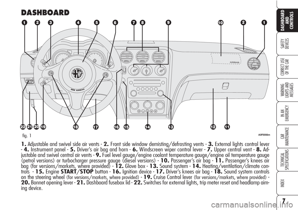
A0F0056mfig. 1
1.Adjustable and swivel side air vents - 2.Front side window demisting/defrosting vents - 3.External lights control lever
-4.Instrument panel - 5.Driver’s air bag and horn - 6.Windscreen wiper control lever - 7.Upper central vent - 8.Ad-
justable and swivel central air vents - 9.Fuel level gauge/engine coolant temperature gauge/engine oil temperature gauge
(petrol versions) or turbocharger pressure gauge (diesel versions) - 10.Passenger’s air bag - 11.Passenger’s knees air
bag (for versions/markets, where provided) - 12.Glove box - 13.Sound system - 14.Heating/ventilation/climate con-
trols - 15.EngineSTART/STOPbutton - 16.Ignition device - 17.Driver’s knees air bag - 18.Sound system controls
on the steering wheel
(for versions/markets, where provided)-19.Cruise Control lever (for versions/markets, where provided)-
20.Bonnet opening lever - 21.Dashboard fusebox lid - 22.Switches for external lights, trip meter reset and headlamp aim-
ing device.
Page 27 of 271
25
SAFETY
DEVICES
WARNING
LIGHTS AND
MESSAGES
IN AN
EMERGENCY
CAR
MAINTENANCE
TECHNICAL
SPECIFICATIONS
INDEX
DASHBOARD
AND
CONTROLS
CORRECT USE
OF THE CAR
AUTOMATIC INSTRUMENT
PANEL LIGHT DIMMER
To give max. visibility and comfort un-
der whatever driving conditions (e.g.:
lights on in daylight, tunnels, etc…), the
speedometer is fitted with a sensor for
adjusting automatically, after fitting the
electronic key into the ignition device and
pressing button START/STOP, the
light intensity of the instrument panel dis-
play, sound system display, climate con-
trol system display, radionavigation sys-
tem display (for versions/markets,
where provided), and instruments (i.e.:
fuel level gauge, engine oil temperature
gauge for petrol versions or turbocharg-
er pressure gauge for diesel versions, and
engine coolant temperature gauge).
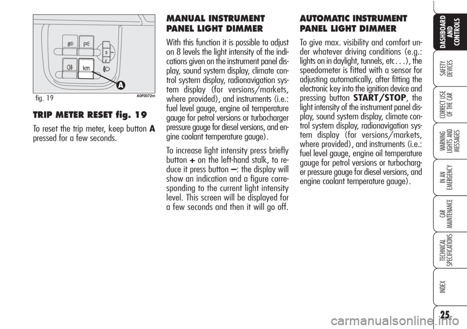
TRIP METER RESET fig. 19
To reset the trip meter, keep button A
pressed for a few seconds.
MANUAL INSTRUMENT
PANEL LIGHT DIMMER
With this function it is possible to adjust
on 8 levels the light intensity of the indi-
cations given on the instrument panel dis-
play, sound system display, climate con-
trol system display, radionavigation sys-
tem display (for versions/markets,
where provided), and instruments (i.e.:
fuel level gauge, engine oil temperature
gauge for petrol versions or turbocharger
pressure gauge for diesel versions, and en-
gine coolant temperature gauge).
To increase light intensity press briefly
button+on the left-hand stalk, to re-
duce it press button –: the display will
show an indication and a figure corre-
sponding to the current light intensity
level. This screen will be displayed for
a few seconds and then it will go off.
A0F0072mfig. 19
Page 31 of 271
29
SAFETY
DEVICES
WARNING
LIGHTS AND
MESSAGES
IN AN
EMERGENCY
CAR
MAINTENANCE
TECHNICAL
SPECIFICATIONS
INDEX
DASHBOARD
AND
CONTROLS
CORRECT USE
OF THE CAR
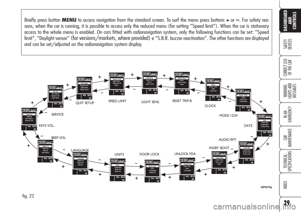
Briefly press button MENUto access navigation from the standard screen. To surf the menu press buttons +or–. For safety rea-
sons, when the car is running, it is possible to access only the reduced menu (for setting “Speed limit”). When the car is stationary
access to the whole menu is enabled. On cars fitted with radionavigation system, only the following functions can be set: “Speed
limit”, “Daylight sensor”
(for versions/markets, where provided)e “S.B.R. buzzer reactivation”. The other functions are displayed
and can be set/adjusted on the radionavigation system display.
fig. 22
BEEP VOL.SERVICEQUIT SETUPLIGHT SENS.RESET TRIP B
CLOCK
MODE 12/24
DATE
AUDIO RPT.
INDEP. BOOT
UNLOCK FDA
DOOR LOCK
UNITS KEYS VOL.
LANGUAGESPEED LIMIT
A0F0218g
Page 32 of 271
30
SAFETY
DEVICES
WARNING
LIGHTS AND
MESSAGES
IN AN
EMERGENCY
CAR
MAINTENANCE
TECHNICAL
SPECIFICATIONS
INDEX
DASHBOARD
AND
CONTROLS
CORRECT USE
OF THE CAR
Automatic headlight daylight
sensor (Light Sens.)
(for versions/markets,
where provided)
With this function it is possible to adjust
the light sensor sensitivity according to
3 levels.
To adjust the volume proceed as follows:
❒briefly press button MENU: the pre-
viously set level will be displayed;
❒press button +or–for setting as re-
quired;
❒briefly press buttonMENUto go
back to the menu screen or press the
button for long to go back to the
standard screen.
Reset Trip B
This function enables to select Trip B re-
set mode (Automatic or Manual).
For further information see paragraph
“Trip computer”. Speed limit (Speed limit)
With this function it is possible to set the
car speed limit (km/h or mph), which,
if exceeded, automatically sounds a
buzzer and displays a special message
(see section “Warning lights and mes-
sages”) to alert the driver.
To set the speed limit, proceed as fol-
lows:
❒briefly press button MENU:OFF
will be displayed;
❒press button +:ONwill be dis-
played;
❒briefly press button MENUthen,
use buttons +/–to set the required
speed (during setting the value will
flash).
❒briefly press button MENUto go
back to the menu screen or press the
button for long to go back to the
standard screen.IMPORTANTThe possible setting is
between 30 and 250 km/h (or be-
tween 20 and 150 mph) depending on
the unit set previously (see paragraph
“Units” described later). Every press
(pulse) of the button +/–increases or
decreases the value by 5 units. Keeping
the button +/–pressed obtains auto-
matic fast increase or decrease. When
you are near the required setting com-
plete adjustment with single presses.
To abort the setting:
❒briefly press button MENU:ON
will be displayed;
❒press button –:OFFwill be dis-
played;
❒briefly press button MENUto go
back to the menu screen or press the
button for long to go back to the
standard screen.
Page 38 of 271
36
SAFETY
DEVICES
WARNING
LIGHTS AND
MESSAGES
IN AN
EMERGENCY
CAR
MAINTENANCE
TECHNICAL
SPECIFICATIONS
INDEX
DASHBOARD
AND
CONTROLS
CORRECT USE
OF THE CAR
Reactivating the S.B.R.
(Seat Belt Reminder)
buzzer (Beep Seatb.)
This function is displayed only after the
system has been deactivated by Alfa
Romeo Authorized Services.
Exit Menu (Quit setup)
Selecting this option will bring back to
standard screen.ILLUMINATION OF REV
COUNTER/INSTRUMENTS
(NIGHT PANEL)
This function enables to turn on/off
(ON/OFF) the lights of the rev counter
and instruments. This function can be ac-
tivated (only with electronic key fitted in-
to ignition device, external lights on, and
speedometer built-in sensor at poor out-
side light setting), by pressing for long but-
ton–. When this function is on, the dis-
play will show a warning message.
Once on, the NIGHT PANELfunction
can be deactivated as follows:
❒by long press on button +(also with
external lights off);
❒removing the electronic key from the
ignition device.
When function is off the display will show
a warning message.
Messages stay on the display for a few
seconds, then they will go off. To stop
displaying before time, briefly press but-
tonMENU. Scheduled Servicing (Service)
Through this function it is possible to dis-
play information connected to proper car
servicing.
Proceed as follows:
❒briefly press button MENU: service
in km or mi, according to previous
setting, will be displayed (see para-
graph “Units”);
❒briefly press buttonMENUto go
back to the menu screen or press the
button for long to go back to the
standard screen.
IMPORTANTThe Service schedule in-
cludes car maintenance every 35,000 km
(or 21,000 mi); this is shown automat-
ically, with the electronic key into the ig-
nition device starting from 2,000 km (or
1,240 mi) from this deadline and it will
be displayed in km or miles according to
the unit set. When a scheduled service in-
terval (“coupon”) is near to come, fitting
the electronic key into the ignition device
will display a message followed by the
number of km/mi to go before car ser-
vicing. Contact Alfa Romeo Authorized Ser-
vices to carry out any service operation
provided by the Service schedule or by the
Annual inspection plan, and to reset the
display.
Page 39 of 271
37
SAFETY
DEVICES
WARNING
LIGHTS AND
MESSAGES
IN AN
EMERGENCY
CAR
MAINTENANCE
TECHNICAL
SPECIFICATIONS
INDEX
DASHBOARD
AND
CONTROLS
CORRECT USE
OF THE CAR
Reset TRIP B
End of partial mission
Start of new partial mission End of partial mission
Start of new
partial mission
Reset TRIP B
End of partial mission
Start of new
partial mission Reset GENERAL TRIP
End of complete mission
Start of new missionReset GENERAL TRIP
End of complete mission
Start of new mission
End of partial mission
Start of new
partial mission Reset TRIP B
Reset TRIP B TRIP B
TRIP B
TRIP B GENERAL TRIP
˙
˙
˙
˙˙
˙
˙ ˙
fig. 23
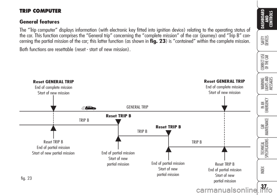
TRIP COMPUTER
General features
The “Trip computer” displays information (with electronic key fitted into ignition device) relating to the operating status of
the car. This function comprises the “General trip” concerning the “complete mission” of the car (journey) and “Trip B” con-
cerning the partial mission of the car; this latter function (as shown in fig. 23) is “contained” within the complete mission.
Both functions are resettable (reset - start of new mission).
Page 41 of 271
39
SAFETY
DEVICES
WARNING
LIGHTS AND
MESSAGES
IN AN
EMERGENCY
CAR
MAINTENANCE
TECHNICAL
SPECIFICATIONS
INDEX
DASHBOARD
AND
CONTROLS
CORRECT USE
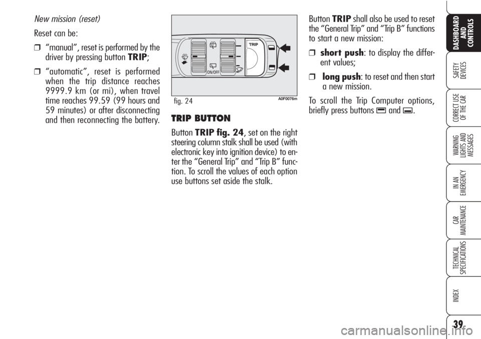
OF THE CARTRIP BUTTON
ButtonTRIP fig. 24, set on the right
steering column stalk shall be used (with
electronic key into ignition device) to en-
ter the “General Trip” and “Trip B” func-
tion. To scroll the values of each option
use buttons set aside the stalk.ButtonTRIPshall also be used to reset
the “General Trip” and “Trip B” functions
to start a new mission:
❒ short push: to display the differ-
ent values;
❒ long push: to reset and then start
a new mission.
To scroll the Trip Computer options,
briefly press buttons
-and..
New mission (reset)
Reset can be:
❒“manual”, reset is performed by the
driver by pressing button TRIP;
❒“automatic”, reset is performed
when the trip distance reaches
9999.9 km (or mi), when travel
time reaches 99.59 (99 hours and
59 minutes) or after disconnecting
and then reconnecting the battery.
A0F0076mfig. 24
Page 42 of 271
40
SAFETY
DEVICES
WARNING
LIGHTS AND
MESSAGES
IN AN
EMERGENCY
CAR
MAINTENANCE
TECHNICAL
SPECIFICATIONS
INDEX
DASHBOARD
AND
CONTROLS
CORRECT USE
OF THE CARIMPORTANT“General Trip” reset will
also reset the “Trip B” function, where-
as “Trip B” reset will only reset the in-
formation associated with this function.
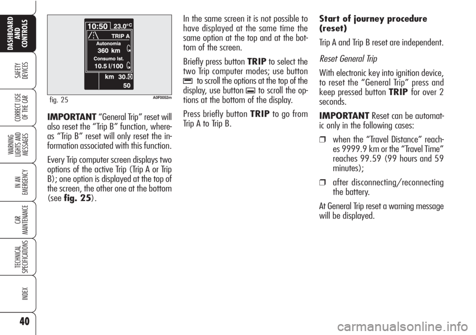
Every Trip computer screen displays two
options of the active Trip (Trip A or Trip
B); one option is displayed at the top of
the screen, the other one at the bottom
(seefig. 25).In the same screen it is not possible to
have displayed at the same time the
same option at the top and at the bot-
tom of the screen.
Briefly press button TRIPto select the
two Trip computer modes; use button
-to scroll the options at the top of the
display, use button
.to scroll the op-
tions at the bottom of the display.
Press briefly button TRIPto go from
Trip A to Trip B.Start of journey procedure
(reset)
Trip A and Trip B reset are independent.
Reset General Trip
With electronic key into ignition device,
to reset the “General Trip” press and
keep pressed button TRIPfor over 2
seconds.
IMPORTANTReset can be automat-
ic only in the following cases:
❒when the “Travel Distance” reach-
es 9999.9 km or the “Travel Time”
reaches 99.59 (99 hours and 59
minutes);
❒after disconnecting/reconnecting
the battery.
At General Trip reset a warning message
will be displayed.
A0F0052mfig. 25
Page 55 of 271
53
SAFETY
DEVICES
WARNING
LIGHTS AND
MESSAGES
IN AN
EMERGENCY
CAR
MAINTENANCE
TECHNICAL
SPECIFICATIONS
INDEX
DASHBOARD
AND
CONTROLS
CORRECT USE
OF THE CAR
CLIMATE CONTROL
(fast cooling)
IMPORTANTThe compressor √can
be enabled only if the ventilation is en-
abled.
Proceed as follows:
❒turn knob Acompletely leftwards;
❒turn knob Cto top speed;
❒turn knob BtoO;
❒press buttons √andv(buttons
leds on).
How to keep the required
cooling
Proceed as follows:
❒turn air recirculation off (if on).
❒turn knob Ato the required tem-
perature;
❒turn the knurled ring Cto the re-
quired fan speed.
LOOKING AFTER
THE SYSTEM
During the winter, the climate control
system
√must be turned on at least
once a month for about ten minutes.
Before summer, have the system
checked at Alfa Romeo Authorized Ser-
vices.
RECIRCULATION
To turn this function on press button
v: the button led will turn on.
This function is particularly useful when
the outside air is heavily polluted (in a
traffic jam, tunnel, etc.) However, it is
better not to use it for long periods, es-
pecially if there are several people in the
car to prevent window misting up.
Do not use the air recirculation function
on rainy/cold days as it would consid-
erably increase the possibility of the win-
dows misting inside.
IMPORTANTThe inside air recircula-
tion system makes it possible to reach
the required (“heating” or “cooling”)
conditions faster.
After connecting/discon-
necting the battery,
wait for 3 minutes at
least before fitting the elec-
tronic key into the ignition de-
vice in order to allow the cli-
mate control system control unit
to reset the positions of the
electric actuators that adjust air
temperature and distribution.
Page 56 of 271
54
SAFETY
DEVICES
WARNING
LIGHTS AND
MESSAGES
IN AN
EMERGENCY
CAR
MAINTENANCE
TECHNICAL
SPECIFICATIONS
INDEX
DASHBOARD
AND
CONTROLS
CORRECT USE
OF THE CARTo guarantee perfect
and regular sensor op-
eration do not apply
stickers in the “monitoring”
area between sensor and wind-
screen. Keep windscreen and
sensor clean and avoid to accu-
mulate dust or other sub-
stances.
AUTOMATIC
TWO-ZONE CLIMATE
CONTROL SYSTEM
(for versions/markets,
where provided)
DESCRIPTION
The car is fitted with a two-zone climate
control system which makes it possible
to separately adjust the air temperature
in the two passenger’s compartment ar-
eas to reach the required comfort.
To obtain top control of both zones, the
system is fitted with outside temperature
sensor, passenger’s compartment tem-
perature sensor and bilateral sun radia-
tion sensor.
The climate control system automatically
controls and adjusts the following pa-
rameters and functions:
❒air temperature at driver/passengers
vents;
❒fan speed;
❒air distribution at driver/passenger
vents;
❒compressor activation;
❒air recirculation.
The following parameters and functions
can be set or changed manually:
❒required temperature;
❒fan speed;
❒air distribution on seven levels;
❒compressor on/off;
❒window demisting/defrosting;
❒air recirculation.
The system is fitted with AQS (Air Qual-
ity System) sensor (where provided),
that turns on air recirculation automati-
cally when it detects the presence of out-
side polluted air (for example in queues
and tunnels).
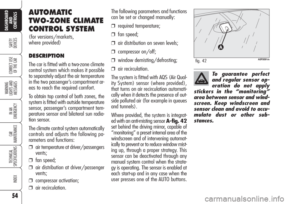
Where provided, the system is integrat-
ed with an anti-misting sensor A-fig. 42
set behind the driving mirror, capable of
“monitoring” a preset internal area of the
windscreen and of intervening automat-
ically to prevent or to reduce window mist-
ing up, through a proper strategy. This
sensor can be deactivated through any
manual system control when the strate-
gy is operating. The sensor is enabled at
each start-up and in any case when the
user presses one of the AUTO buttons.
A0F0091mfig. 42