ASTON MARTIN DB7 1997 Workshop Manual
Manufacturer: ASTON MARTIN, Model Year: 1997, Model line: DB7, Model: ASTON MARTIN DB7 1997Pages: 421, PDF Size: 9.31 MB
Page 391 of 421
The Aston Martin Lagonda Diagnostic System
Users Guide ^=2?
Transmission Diagnostics
Automatic transmission DB7s are fitted with a GM4L80-
E gearbox electronically controlled by a Transmission
Control Unit (TCM)
The TCM is mounted on the rear left wheel
arch.
It may be
electronically accessed from the upper diagnostic socket.
The TCM continuously monitors requests made by the
driver via the gear selector, throttle pedal, mode switch,
etc. This data is used in conjunction with speed input from
the transmission unit to calculate the optimum shift points
undercurrentconditions.Shiftpressureand ignition retard
are also controlled from this data to enhance shift quality
and reduce transmission wear.
TheTCM also detects faults within the transmission system
and stores the relevant fault codes for later analysis.
Gearshifts are controlled by two solenoid valves and a
pressure regulator within the transmission valve block
assembly.
If a serious fault occurs, the TCM removes all electrical
power from these valves and the transmission defaults to
a 'limp home' condition. In this state, only mechanical
selection of either reverse or second gear is available.
Gearshift Timing
Inputs from the performance mode switch (Sport, Normal
or 1st Gear Inhibit) and the throttle position sensor are
used to modify transmission gearshift operation
as
required
by the driver.
Sport mode raises the roadspeed at which gearshifts occur
enabling higher acceleration rates for the vehicle.
1st gear inhibit prevents engagement of first gear to reduce
the risk of wheel slip in icy conditions.
The throttle position sensor signal is continuously
monitored by the TCM to detect a rapid throttle opening.
If the throttle position sensor signal rises rapidly to above
4.5 volts, a 'Kickdown' condition is initiated. In this
condition,
upshifts are delayed to higher road speeds to
provide the higher acceleration required for overtaking
etc.
TCM - PCM Communication
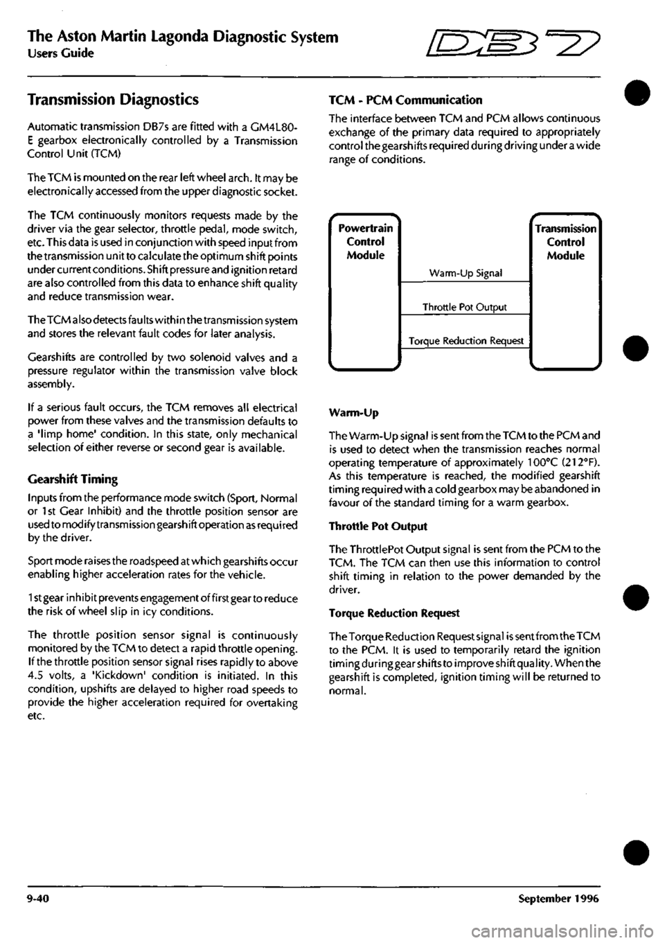
The interface between TCM and PCM allows continuous
exchange of the primary data required to appropriately
control the gearshifts required during driving under
a
wide
range of conditions.
Powertrain
Control
Module
^.. ^
Warm-Up Signal
Throttle Pot Output
Torque Reduction Request
^ •- -^ Transmission
Control
Module
Warm-Up
The Warm-Up signal is sent from the TCM to the PCM and
is used to detect when the transmission reaches normal
operating temperature of approximately 100°C (212"'F).
As this temperature is reached, the modified gearshift
timing required with a cold gearbox may be abandoned in
favour of the standard timing for a warm gearbox.
Throttle Pot Output
The ThrottlePot Output signal is sent from the PCM to the
TCM.
The TCM can then use this information to control
shift timing in relation to the power demanded by the
driver.
Torque Reduction Request
The Torque Reduction Requestsignai
is
sent from the TCM
to the PCM. it is used to temporarily retard the ignition
timing during gear shifts to improve shift quality. When the
gearshift is completed, ignition timing will be returned to
normal.
9-40 September 1996
Page 392 of 421
^^?
The Aston Martin Lagonda Diagnostic System
Users Guide
Transmission Diagnostics
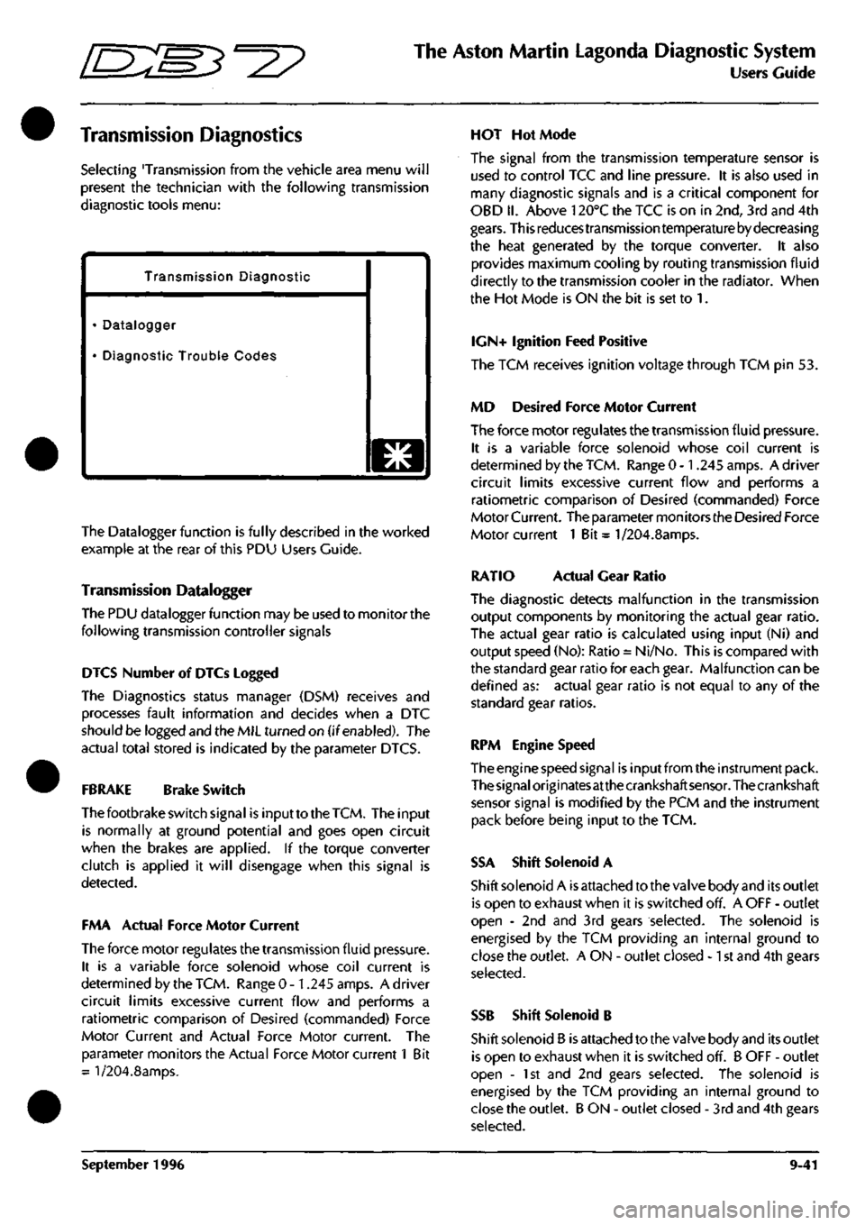
Selecting 'Transmission from the vehicle area menu will
present the technician with the following transmission
diagnostic tools menu:
Transmission Diagnostic
• Datalogger
• Diagnostic Trouble Codes
o
The Datalogger function is fully described in the worked
example at the rear of this PDU Users Guide.
Transmission Datalogger
The PDU datalogger function may be used to monitor the
following transmission controller signals
DIGS Number of DTCs Logged
The Diagnostics status manager (DSM) receives and
processes fault information and decides when a DTC
should be logged and the MIL turned on (if enabled). The
actual total stored is indicated by the parameter DTCS.
FBRAKE Brake Switch
The footbrake switch signal is input to the
TCM.
The input
is normally at ground potential and goes open circuit
when the brakes are applied. If the torque converter
clutch is applied it will disengage when this signal is
detected.
FMA Actual Force Motor Current
The force motor regulates the transmission fluid pressure.
It is a variable force solenoid whose coil current is
determined by the TCM. Range 0 -1.245 amps. A driver
circuit limits excessive current flow and performs a
ratiometric comparison of Desired (commanded) Force
Motor Current and Actual Force Motor current. The
parameter monitors the Actual Force Motor current 1 Bit
= l/204.8amps.
HOT Hot Mode
The signal from the transmission temperature sensor is
used to control TCC and line pressure. It is also used in
many diagnostic signals and is a critical component for
OBD II. Above 120°C the TCC is on in 2nd, 3rd and 4th
gears.
This reduces transmission temperature by decreasing
the heat generated by the torque converter. It also
provides maximum cooling by routing transmission fluid
directly to the transmission cooler in the radiator. When
the Hot Mode is ON the bit is set to 1.
IGN+ Ignition Feed Positive
The TCM receives ignition voltage through TCM pin 53.
MD Desired Force Motor Current
The force motor regulates the transmission fluid pressure.
It is a variable force solenoid whose coil current is
determined by the TCM. Range 0 -1.245 amps. A driver
circuit limits excessive current flow and performs a
ratiometric comparison of Desired (commanded) Force
Motor Current. The parameter mon itors the Desired Force
Motor current 1 Bit = 1/204.8amps.
RATIO Actual Gear Ratio
The diagnostic detects malfunction in the transmission
output components by monitoring the actual gear ratio.
The actual gear ratio is calculated using input (Ni) and
output speed (No): Ratio = Ni/No. This is compared with
the standard gear ratio for each gear. Malfunction can be
defined as: actual gear ratio is not equal to any of the
standard gear ratios.
RPM Engine Speed
The engine speed signal is input from the instrument pack.
The
signal
origi
nates
at the crankshaft
sensor.
The crankshaft
sensor signal is modified by the PCM and the instrument
pack before being input to the TCM.
SSA Shift Solenoid A
Shift solenoid A is attached to the valve body and its outlet
is open to exhaust when it is switched off. A OFF - outlet
open - 2nd and 3rd gears selected. The solenoid is
energised by the TCM providing an internal ground to
close the outlet. A ON - outlet closed -1 st and 4th gears
selected.
SSB Shift Solenoid B
Shift solenoid B is attached to the valve body and its outlet
is open to exhaust when it is switched off. B OFF - outlet
open - 1st and 2nd gears selected. The solenoid is
energised by the TCM providing an internal ground to
close the outlet. B ON - outlet closed - 3rd and 4th gears
selected.
September 1996 9-41
Page 393 of 421
The Aston Martin Lagonda Diagnostic System
Users Guide ^7
TCCS Torque Convertor Clutch Solenoid
The torque converter clutch solenoid is mounted on the
valve body. The signal is Pulse Width Modulated at 32Hz
to provide closed loop control of the pressure across the
converter clutch plates. 1 bit = 0.39% Range 0 to 100%
TP Throttle Position
This is provided by the EECV Engine Management System
as a Pulse Width Modulated signal derived from the
throttle position signal read by that module from the
throttle position sensor.
TCS Torque Convertor Slip
Torque converter slip is defined
as
the difference between
the Input/turbine (ni) speed and the Engine speed (Ne):
Slip = Ne-Ni. The PWM duty cycle may increase from 0
to 100% when TCC is fully applied. In practice a 100%
duty cycle will be achieved only if
a
large slip is detected.
Normal ly only a 50 to 95% duty cycle will be required for
full application of the TCC. Slip is expressed in rpm. 1 Bit
- 1/8 rpm. Range -4096 to +4096 rpm.
TCSW Transmission Control Switch
A three position switch allows the driver to select Sport,
Normal or 1st Gear Inhibit mode. When 'Sport' is selected
gearshifts take place at higher engine revs. When '1st
Gear Inhibit' is selected, the transmission only operates in
the higher forward ratios to prevent wheel slip in icy
conditions.
TISSA Turbine Input Shaft Speed
Turbine speed is the speed of the input shaft of the
transmission measured by the input speed sensor mounted
on the transmission. An alternating waveform is induced
in the sensor by 31 serrations on the forward clutch
housing as it rotates. The waveform frequency and
amplitude is low at low speeds and high at high speeds.
The TCM changes this signal into a digital signal. 1 bit =
1/8 RPM. Range: 0 - 8192 RPM.
TOS+ Transmission Output Speed
The output speed sensor is mounted on the transmission
case and measures the speed of the output shaft. As the
shaft rotates an alternating waveform is induced in the
sensor which varies in frequency and voltage. The wave
form is converted into
a
digital signal by the TCM and used
to control TCC, line pressure, shift timing and torque
management. 1 bit = 1/8 RPM. Range 0-8192 RPM
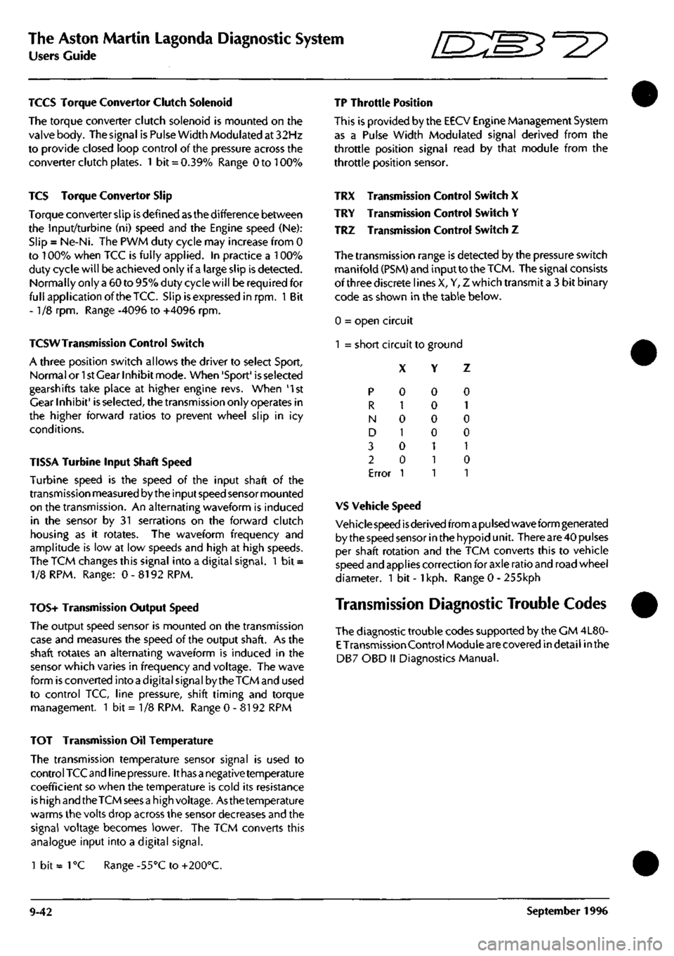
TRX Transmission Control Switch X
TRY Transmission Control Switch Y
TRZ Transmission Control Switch Z
The transmission range is detected by the pressure switch
manifold (PSM) and input to the
TCM.
The signal consists
of three discrete lines X, Y, Z which transmit a 3 bit binary
code as shown in the table below.
0 = open circuit
1 = short circuit to ground
X Y Z
p
R
N
D
3
2
Error
0
1
0
1
0
0
1
0
0
0
0
1
1
1
0
1
0
0
1
0
1
VS Vehicle Speed
Veh icie speed
is
derived from
a pu Ised
wave form generated
by the speed sensor in the hypoid unit. There are 40 pulses
per shaft rotation and the TCM converts this to vehicle
speed and applies correction for axle ratio and road wheel
diameter. 1 bit -
1
kph. Range 0 - 255kph
Transmission Diagnostic Trouble Codes
The diagnostic trouble codes supported by the CM 4L80-
E
Transmission Control Module are covered indetail inthe
DB7 OBD II Diagnostics Manual.
TOT Transmission Oil Temperature
The transmission temperature sensor signal is used to
control TCC and line
pressure.
It
has a
negative temperature
coefficient so when the temperature is cold its resistance
is high and the TCM sees
a
high voltage. Asthe temperature
warms the volts drop across the sensor decreases and the
signal voltage becomes lower. The TCM converts this
analogue input into a digital signal.
1 bit =
1
°C Range -55°C to +200°C.
9-42 September 1996
Page 394 of 421
^?
The Aston Martin Lagonda Diagnostic System
Users Guide
Climate Control Diagnostics
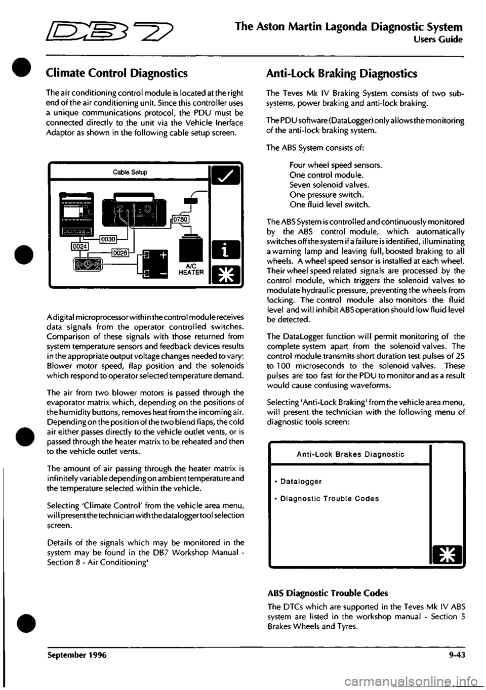
The air conditioning control module is located at the right
end of the air conditioning unit. Since this controller uses
a unique communications protocol, the PDU must be
connected directly to the unit via the Vehicle Inerface
Adaptor as shown in the following cable setup screen.
Cable Setup
Adigitalmicroprocessorwithin the control module receives
data signals from the operator controlled switches.
Comparison of these signals with those returned from
system temperature sensors and feedback devices results
in the appropriate output voltage changes needed to vary:
Blower motor speed, flap position and the solenoids
which respond to operator selected temperature demand.
The air from two blower motors is passed through the
evaporator matrix which, depending on the positions of
the humidity buttons, removes heat from the incoming air.
Dependingon the position of the two blend flaps, the cold
air either passes directly to the vehicle outlet vents, or is
passed through the heater matrix to be reheated and then
to the vehicle outlet vents.
The amount of air passing through the heater matrix is
infinitely variable depending on ambienttemperature and
the temperature selected within the vehicle.
Selecting 'Climate Control' from the vehicle area menu,
will presentthetechnician with the dataloggertool selection
screen.
Details of the signals which may be monitored in the
system may be found in the DB7 Workshop Manual -
Section 8 - Air Conditioning'
Anti-Lock Braking Diagnostics
The Teves Mk IV Braking System consists of two sub
systems, power braking and anti-lock braking.
The PDU software(DataLogger) only allows the monitoring
of the anti-lock braking system.
The ABS System consists of:
Four wheel speed sensors.
One control module.
Seven solenoid valves.
One pressure switch.
One fluid level switch.
The ABS System
is
controlled and continuously monitored
by the ABS control module, which automatically
switchesoffthesystemifafailure is identified, illuminating
a warning lamp and leaving
full,
boosted braking to all
wheels. A wheel speed sensor is installed at each wheel.
Their wheel speed related signals are processed by the
control module, which triggers the solenoid valves to
modulate hydraulic pressure, preventing the wheels from
locking.
The control module also monitors the fluid
level and will inhibit ABS operation should lowfluid level
be detected.
The Datalogger function will permit monitoring of the
complete system apart from the solenoid valves. The
control module transmits short duration test pulses of 25
to 100 microseconds to the solenoid valves. These
pulses are too fast for the PDU to monitor and as a result
would cause confusing waveforms.
Selecting 'Anti-Lock Braking' from the vehicle area menu,
will present the technician with the following menu of
diagnostic tools screen:
Anti-Lock Brakes Diagnostic
Datalogger
Diagnostic Trouble Codes
o
ABS Diagnostic Trouble Codes
The DTCs which are supported in the Teves Mk IV ABS
system are listed in the workshop manual - Section 5
Brakes Wheels and Tyres.
September 1996 9-43
Page 395 of 421
The Aston Martin Lagonda Diagnostic System
Users Guide
Em^'^?
ABS Datalogger
The following signals in the Teves Mk IV ABS system may
be monitored using the datalogger function.
DTCs Number of DTCs Logged
The Diagnostic status manager (DSM) receives and
processes fault information and decides when a DTC
should be logged and the MIL turned on. The actual total
stored is indicated by the parameter.
FBRAKE Brake Switch
The signal from the brake switch is used by the CM to
ensure that traction control is inhibited when the brakes
are applied. The input circuitry within the CM is a
1
OK
pull-up to ignition voltage. When the switch is closed the
parameter is set to 1.
FLWS Front Left Wheel Speed Sensor
An indication sensor outputs a sinusoidal wave form 48
pulses per revolution. The output is processed by the CM
to control braking and traction. The sensor is continually
monitored for open and short failure and operating range.
If its output exceeds 330km/h it is deemed to be faulty and
the CM is disabled. The parameter tracks the sensor
weaveform through 255 steps.
FRWS Front Right Wheel Speed Sensor
An indication sensor outputs a sinusoidal wave form 48
pulses per revolution. The output is processed by the CM
to control braking and traction. The sensor is continually
monitored for open and short failure and operating range.
If its output exceeds 330km/h it
is
deemed to be faulty and
the CM is disabled. The parameter tracks the sensor
weaveform through 255 steps.
RLWS Rear Left Wheel Speed Sensor
An indication sensor outputs a sinusoidal wave form 48
pulses per revolution. The output is processed by the CM
to control braking and traction. The sensor is continually
monitored for open and short failure and operating range.
If its output exceeds 330km/h it
is
deemed to be faulty and
the CM is disabled. The parameter tracks the sensor
weaveform through 255 steps.
RRWS Rear Right Wheel Speed Sensor
An indication sensor outputs a sinusoidal wave form 48
pulses per revolution. The output is processed by the CM
to control braking and traction. The sensor is continually
monitored for open and short failure and operating range.
If its output exceeds 330km/h it is deemed to be faulty and
the CM is disabled. The parameter tracks the sensor
waveform through 255 steps.
Passive Anti Theft (PATS) Diagnostics
Security System Diagnostics
Becauseof the requirementto maintain vehicle security,
the PATS and Security System operating instructions
and diagnostics are covered in the Vehicle Security
supplement to section 6 of the workshop manual. This
supplement has restricted circulation and is only
available to Aston Martin Dealers.
9-44 September 1996
Page 396 of 421

^^2?
The Aston Martin Lagonda Diagnostic System
Users Guide
Airbag System Diagnostics
WARNING: Whilst it
is
completely safe to
access
and read the airbag diagnostic module memory at
the diagnostic socket, significant personal risks
exist in the performance of any other
tasks
on the
airbag system or components. Therefore all
workshop manual warnings must be read and all
safety procedures must be followed before, during
and on completion of any other practical work on
the airbag system.
System Description
The airbag system installation comprises:
Airbag Diagnostic Module
Driver and passenger airbag modules
Two front impact (crash) sensors
One 'safing' sensor
Dedicated wiring harness
SRS indicator/warning lamp
The system is designed to provide protection for both
driver and front seat passenger by automatically
deploying airbags in the event of a collision during
forward travel.
Intheeventof
a
collision, the crash and safing sensors
will operate, completing the firing circuit and causing
the airbags to inflate within 32 milliseconds. At least
one crash sensor and the safing sensor must operate to
fire the airbags.
Any faults in system components, installation or wiring
will be indicated by a flashing code on the SRS/
AIRBAG warning lamp. Fault code information may
also be monitored using the PDU or scan
tool.
A full description of the airbag system components is
included in the workshop manual.
Airbag Diagnostics
The Airbag Control Module indicates a fault by
transmitting a pulsed signal down the Airbag System
Failure line to flash the SRS/AIRBAC warning lamp.
The fault code is repeated continuously. If there are
two or more faults, the fault code with the highest
priority is transmitted first. The second fault code is
only transmitted when the first fault has been rectified.
TheSRS/AIRBAC warning lamp is also used to indicate
any problem in the seat belt pretensioner system (if
fitted). Flashing of the lamp indicates an airbag fault,
constant illumination of the lamp indicates a seat belt
pretensioner fault.
At the top left of the PDU screen there is a bullet mark
which indicates the current state of the Airbag System
Failure line. As a code is transmitted the bullet mark
can be seen to flash.The PDU reads the fault code, and
writes the code number and fault description to the
screen.
The PDU continues to monitor the transmitted
code.
If the transmitted code changes, the new code
number and description will appear below the first.
PMC Airbag
32 Drivers airbag circuit
shorted or open
o
when remedial action has been taken to correct a
fault, press the Clear Button to clear down the PDU
display. Then use the PDU to ensure that no faults are
reported.
A series of audible beeps, continuously transmitted by
the Airbag Diagnostic Module, indicates that there is
an Airbag System fault to report and that the Airbag
System Failure line
is
open circuit. The PDU is notable
to monitor the fault line in this situation as there is no
pull-up resistor, normally provided by a warning lamp
in the instrument pack.
Rapid continuous flashing of the Instrument Pack
Airbag Failure Lamp indicates that both front impact
sensors are disconnected. No fault code is reported on
the PDU, however on close inspection the bullet mark
can be seen to flicker.
September 1996 9-45
Page 397 of 421

The Aston Martin Lagonda Diagnostic System //~~^ ^?~?^ " ^ ^
Users Guide
Airbag Diagnostic Trouble Code Monitor
The following diagnostic trouble codes are supported by the Airbag Control Module:
12 Low battery voltage
13 Air bag circuit shorted to ground
14 Front inpact sensor circuit shorted to ground
21 Safing impact sensor incorrectly mounter to vehicle
22 Safing impact sensor output shorted to battery voltage
23 Safing impact sensor input feed / return open circuit
24 Safing impact sensor output feed / return open circuit
32 Driver side airbag circuit high resistance or open
33 Passenger side airbag circuit high resistance or open
34 Driver side airbag circuit low resistance or short circuit
41 Front right impact sensor feed / return open circuit
42 Front left impact sensor feed / return open circuit
44 Front right impact sensor incorrectly mounted to vehicle
45 Front left impact sensor incorrectly mounted to vehicle
51 Airbag CM internal thermal fuse - intermittent short to ground
52 Back up power supply - voltage boost fault
53 Front impact sensor circuits resistance to ground or internal Airbag CM failure
9-46 September 1996
Page 398 of 421
^^?
The Aston Martin Lagonda Diagnostic System
Users Guide
Seat Belt Pretensioner Diagnostics
(where fitted)
Description
The DB7 seat belt pretensioner system operates the
drivers seat belt pretensioner in conjunction with the
Airbag system. The seat belt pretensioner control
module is located underthe right hand seat, beside the
seat control module.
The pretensioner control module calculates changes
in vehicle speed using an input signal from an
accelerometer. When a collision is detected (Rapid
reduction in vehicle speed) the pretensioner charge is
fired using electrical energy stored in a capacitor
within the pretensioner control module. Firing of the
pretensioner charge applies additional tension to the
drivers seat belt.
The airbag and seat belt pretensioner systems share the
SRS (Airbag) warning lamp. Any fault detected by the
pretensioner control module is indicated by constant
illumination ofthe
SRS
(Airbag) warning
lamp.
Flashing
of the SRS warning lamp indicates a fault in the airbag
system.
Should both systems develop faults, the pretensioner
system will permanently illuminate the warning lamp.
This would mask the airbag system warning indication.
Therefore, rectify the pretensioner fault and then retest
for faults in the airbag system
The pretensioner control module can log up to 10
diagnostic trouble codes together with a time since
each fault was alerted to the driver. Each fault will be
identified as 'Permanent' or 'Intermittent' on the PDU
diagnostic trouble codes screen.
System Connections
The Autoliv RC5 Pretensioner Control Module has an
18 pin connector featuring six shorting bridges. The
mating halves ofthe connector may be securely locked
using a double mechanical locking system.
The following pins on the control module connector
are used in the Aston Martin seat belt pretensioner
system:
Pin 1
Pin 2
Pin n
Pin 12
Pin 14
Pin 15
Case
September 1996
Ground
SRS/Airbag Warning Lamp
Drivers airbag positive
Drivers airbag negative
Serial communications
12 volt positive feed
Ground
System Fault Strategy
No single fault may cause an unexpected deployment.
The controller will supervise the airbag/pretensioner
electrical system in order to warn the driver should a
fault occur. Any fault detected by the self diagnostics
shall cause the airbag warning lamp to be activated,
and in some cases the pretensioner control module to
enter shutdown mode. In shutdown mode, the energy
ofthe reserve capacitors shall be discharged to avoid
unintended deployment.
As the ignition is switched on, the pretensioner
controller will directly discharge theenergy capacitors.
When the start up procedure is completed without
detecting any faults, the converter will be activated
allowing the capacitors to be
charged.
The system shall
be fully active within 11 seconds after switching the
ignition on providing that no faults are detected.
All system faults monitored by the controller are filtered
in software to avoid fault warnings due to transient
electrical disturbances.
If a fault which could lead to inadvertent deployment
bedetectedbythemicroprocessor,asoftwareshutdown
will be generated. However, a leakage to an earth or
positive potential in the pretensioner output circuit
shall not cause the controller to enter shutdown mode.
If
a
permanent short of the ignition transistor occurs, a
shutdown shall be generated by the hardware circuit.
If a shutdown occurs, the system shall be unable to
deploy the pretensioner after a period of
3
seconds (i.e.
capacitors discharged to under minimum deployment
voltage).
WARNING: To avoid the possibility of personal
injury caused by accidental deployment of the
pretensioner, disconnect the vehicle battery and
wait at least 10 minutes for all voltages to fully
discharge before working on the pretensioner
system. This covers the possibility of the normal
capacitor discharge circuits being inopera tive and
failing to discharge the capacitor when instructed
to do so.
If the module enters shutdown mode, all diagnostic
functions are stopped, but the communications link
remains active. A fault code corresponding to the
cause of the problem may be read by the PDU.
9-47
Page 399 of 421
The Aston Martin Lagonda Diagnostic System
Users Guide ^?
Seatbelt Pretensioner Diagnostic Trouble Codes
050A Pretensioner squib leak to battery positive
050B Pretensioner squib leak to ground
050C Pretensioner squib high resistance
050D Pretensioner squib low resistance
0D13 Capacitor voltage error
0D14 Capacitor capacitance
0D09 Energy reserve switch
0D1E Energy shutdown switch
050E Seatbelt pretensioner switch error
0109 Accelerometer function
01OA Acceleration out of range
01
OB Accelerometer offset
0209 Safing sensor error
030A Temperature sensor error
060C Warning lamp short circuit
060D Warning lamp open circuit
060E Warning lamp driver error
OAOC Analogue voltage error
0A09 Communications error
090A EEPROM not programmed
0909 EEPROM checksum
OAOA External watchdog error
OAOB External watchdog time out
020A Safing sensor not closed
090C RAM check error
9-48 September 1996
Page 400 of 421
^^
The Aston Martin Lagonda Diagnostic System
Users Guide
Print Facility
The print trace and print screen facilities provided on
DB7 CD2 will enable the Dealer to print directly to a
serial printer via an isolated RS 232 cable.
General Information
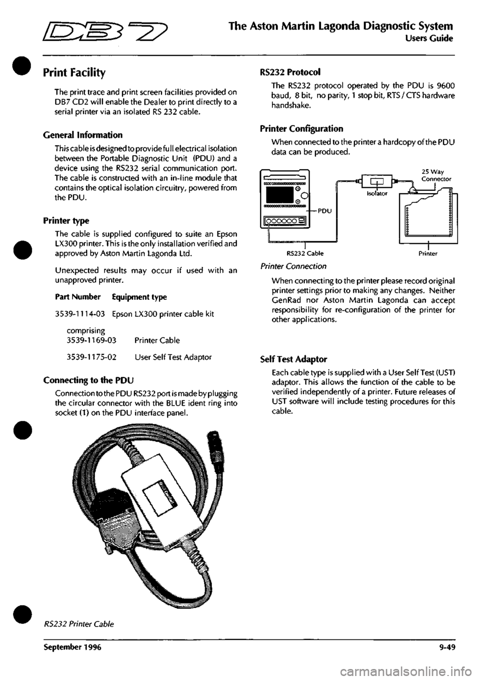
This cable isdesigned to provide full electrical isolation
between the Portable Diagnostic Unit (PDU) and a
device using the RS232 serial communication port.
The cable is constructed with an in-line module that
contains the optical isolation circuitry, powered from
the PDU.
Printer type
The cable is supplied configured to suite an Epson
LX300 printer. This is the only instal lation verified and
approved by Aston Martin Lagonda Ltd.
Unexpected results may occur if used with an
unapproved printer.
Part Number Equipment type
3539-1114-03 Epson LX300 printer cable kit
comprising
3539-1169-03 Printer Cable
3539-1175-02 User Self Test Adaptor
Connecting to the PDU
Connection to the PDU RS232 port
is
made by plugging
the circular connector with the BLUE ident ring into
socket (1) on the PDU interface panel.
RS232 Protocol
The RS232 protocol operated by the PDU is 9600
baud,
8 bit, no parity,
1
stop bit,
RTS
/ CTS hardware
handshake.
Printer Configuration
When connected to the printer
a
hardcopy of the PDU
data can be produced.
25 Way Connector c rp '*= Isolator •—*«
RS232 Cable
Printer Connection
Printer
When connecting to the printer please record original
printer settings prior to making any changes. Neither
CenRad nor Aston Martin Lagonda can accept
responsibility for re-configuration of the printer for
other applications.
Self Test Adaptor
Each cable type is supplied with a User Self Test (UST)
adaptor. This allows the function of the cable to be
verified independently of a printer. Future releases of
UST software will include testing procedures for this
cable.
RS232 Printer Cable
September 1996 9-49