ASTON MARTIN DB7 1997 Workshop Manual
Manufacturer: ASTON MARTIN, Model Year: 1997, Model line: DB7, Model: ASTON MARTIN DB7 1997Pages: 421, PDF Size: 9.31 MB
Page 361 of 421
The Aston Martin Lagonda Diagnostic System
Installation Instructions
[ES^'^?
Powering-Up the Base Station
When first operating the System or when first using
a PDU fitted with substitute batteries, it will take up
to36 hourstoachievefull charge. Inthemeantime,
the PDU can be used whilst connected to the base
station or to the vehicle battery.
Vi/\RNmGS:
When using the system equipment, basic safety
precautions should always be followed, including:
Carefully read and follow all instructions.
Care should be taken as burns can occur from
touching hot parts.
Do not operate the appliance with a damaged
mains lead or if the appliance has been dropped or
damaged. Call your local GenRad Service Centre
immediately for a substitute
part.
Do not let the mains lead hang over the
edge
of the
table, bench or counter or come into contact with
hot manifolds or moving fan blades.
The Aston Martin Portable Diagnostic Unit
is
fitted with an
auto switching power supply suitable for voltage supplies
of 100 - 240 VAC 50 - 60 Hz. You need only check that
the power cord connector is of the correct type for your
power outlets.
1.
Connect the mains lead to the mains outlet.
2.
Check that the green indicator lamp above the base
station door is illuminated. If the green lamp does
not come on, see the problem solving section for
advice.
3. After a few seconds, during which the electronics
module completes its self-test, the red OK indicator
lamp should illuminate. If the red lamp does not
come on, see the problem solving section for
advice.
4.
Allow the base station electronics module to reach
working temperature. This will take approximately
BOminutes, after which time the base station will be
ready to accept the software on CD-ROM.
5. Slide the PDU into its carrying case and place the
associated cables and probes in the carrying case
compartments.
6. Place the carrying case onto the base station at the
far left side (Fig 5). This is the normal place for
charging the battery, loading software and storing
the PDU. Note that it is retained by raised retaining
blocks which fit inside the recesses under the
carrying cases (Fig 5).
7. Remove the protective coverfromthe PDU interface
panel socket (Fig
1
-7.6)
8. Usingthe PDU to base station cable (0064) connect
panel socket 6 to the base station left socket (Fig
1
-
19).
The indicator lamp will glow orange during
fast charge and yellow during trickle charging.
9. A second PDU can be fitted on the central position
on the base station and may be connected to the
right charging socket using a second cable (0064).
Note that both units may be charged simultaneously
but software may only be loaded from CD-ROM
using the left base station socket.
Figure 5. Normal PDU position
9-10 May 1996
Page 362 of 421
'D::B^^?
The Aston Martin Lagonda Diagnostic System
Installation Instructions
Installing the CD-ROM (Early Systems) Installing the CD-ROM (Later Systems)
2.
3.
5.
Ensure that your hands are clean before touching
the CD-ROM disc, disc caddy, or the CD-ROM
drive.
Open the base station door to gain access to the
CD-ROM drive.
Open the CD caddy by squeezing the sides whilst
lifting the hinged door upwards (Fig 6).
Handling the CD by the edges only, remove it from
the protective sleeve and insert it into the caddy
with the image side uppermost. Close the caddy
door.
Insert the CD caddy into the CD drive in the base
station.
Close and lock the CD-ROM drive door.
The base station is now ready for use.
Figure 6. CD-ROM Installation (Early Systems)
Later PDU systems have an improved CD-ROM
drive incorporating a tray loading mechanism for
the CD-ROM disc.
1.
Ensure that your hands are clean before touching
the CD-ROM disc, or the CD-ROM drive.
2.
Open the base station door to gain access to the
CD-ROM drive.
3. Press the tray eject button on the CD-ROM drive
(Fig 7). The tray will open automatically.
4.
Remove the CD from its protective sleeve and place
it on the tray with the image side uppermost.
5. Gently push on the tray and the motorised
mechanism will start to retractthe tray automatically.
Alternatively, pressing the eject button will cause
the tray to close.
6. Close and lock the CD-ROM drive door. The base
station is now ready for use.
Figure 7. CD-ROM Installation (Later Systems)
May 1996 9-11
Page 363 of 421
The Aston Martin Lagonda Diagnostic System
Installation Instructions ^^?
Removing the CD-ROM (Early Systems) Removing the CD-ROM (Later Systems)
1.
Ensure that your hands are clean before touching
the CD-ROM disc, disc caddy, or the CD-ROM
drive.
2.
Unlock and open the CD-ROM drive door.
3. Press the eject button on the CD-ROM drive (Fig
1
-
25).
4.
After a short delay, the CD caddy will be ejected.
Remove the caddy from the CD drive.
5. Open the caddy and remove the CD. Place the CD
into its storage sleeve and store in the base station
drawer (Fig 8).
1.
Ensure that your hands are clean before touching
the CD-ROM disc, or the CD-ROM drive.
2.
Unlock and open the CD-ROM drive door.
3. Press the eject button on the CD-ROM drive (Fig
1
-
25).
4.
The CD tray will open fully. Remove the CD from
the tray.
5. Gently push on the tray or press the eject button
again to close the motorised tray (Fig 9).
Figure 8. CD-ROM Removal (Early Systems)
Figure 9. CD-ROM Removal (Later Systems)
9-12 May 1996
Page 364 of 421
^^?
The Aston Martin Lagonda Diagnostic System
Installation Instructions
Powering-Up the PDU
1.
Install the CD-ROM.
2.
Press the PDU power on switch (Fig 1-2). An
audible tone will be hears and the green PDU
power on indicator (Fig 1-6) will illuminate. The
touch sensitive screen will also be activated. If this
does not happen, see the problem solving section.
3. Adjust the contrast control (Fig
1
-4).
4.
When the PDU is switched on, it will perform an
automaticself-checktotesttheinternal components.
On successful completion of the self-check, a PDU
symbol will appear with a 'tick' next to it (Fig 10).
The PDU will then display the language selection
screen (Fig 11).
5. Select the required language and confirm the
selection (Fig 11).
Hole: PDU text is available in
English,
French,
Italian,
German and Japanese.
6. The PDU will then load its software from the CD-
ROM and display the 'main menu' (Fig 12).
7. New users may select 'Training' and press the 'tick'
icon to enter the on-screen PDU training
programme.
iGenRad V 1.0 (£) 1992
y
Figure 10. Self-check completed screen
Figure 17. Language selection screen
Main Menu
• Run diagnostic
• Digital multimeter
Training
• PDU System self test
Figure 12. The main menu
May 1996 9-13
Page 365 of 421
The Aston Martin Lagonda Diagnostic System
Installation Instructions 5^27
Battery Charging
The PDU is fitted with internal NICAD batteries
which allow the PDU to be transported whilst
retaining programs. The batteries are not designed
to be used as a general power source. A special
circuit monitorstheamountofcharge in the batteries
so that they cannot be overcharged.
From the time when first operating the system or a
PDU fitted with substitute batteries, it will take up
to 36 hours to achieve full charge. In the meantime,
the PDU can be used whilst connected to the base
station or to the vehicle battery. Keep transit times
to and from the vehicle as short as reasonably
possible to preserve battery charge.
Subsequent battery charges
shou Id
take six to seven
hours from fully discharged. The PDU must always
be left connected to the base station when not in
use in order to keep the batteries fully charged.
CAUTION: The rechargeable NICAD batteries
fitted to the PDU are of a special type and must
only be replaced with GenRad approved parts. Do
not substitute the batteries with any other type.
Always
dispose
of old batteries in compliance with
local recycling regulations. The procedure for
changing the battery pack
is
described later in this
installation guide.
Operating Procedures
Refer to the Aston Martin Diagnostic System Users
Guide for detail on each of the PDU software
options
Selecting Diagnostics
1.
Switch on the PDU, the main menu will be
displayed.
2.
Select 'Run Diagnostic' from the main menu and
confirm the selection by pressing the 'tick'
icon.
A
sequence of menus will be displayed requesting
identification of the vehicle under test.
3. The system will load the appropriate software.
4.
On completion of software loading, disconnect the
PDU from the base station and transfer it in its
carrying case to the vehicle. The additional pockets
in the carrying case may be used for carrying any
interface cables required.
5. If the VIA is required, also transfer it in its carrying
case to the vehicle together with any vehicle
interface cable required.
Using the PDU on the Vehicle
At the vehicle, the PDU may be removed from its
carrying case if required. The PDU should always
be connected to the vehicle using the Vehicle
Battery Adaptor (VBA) (0024). The PDU will
continue to charge from the vehicle battery.
Vehicle Battery Adaptor
This unit transforms battery voltage to the correct
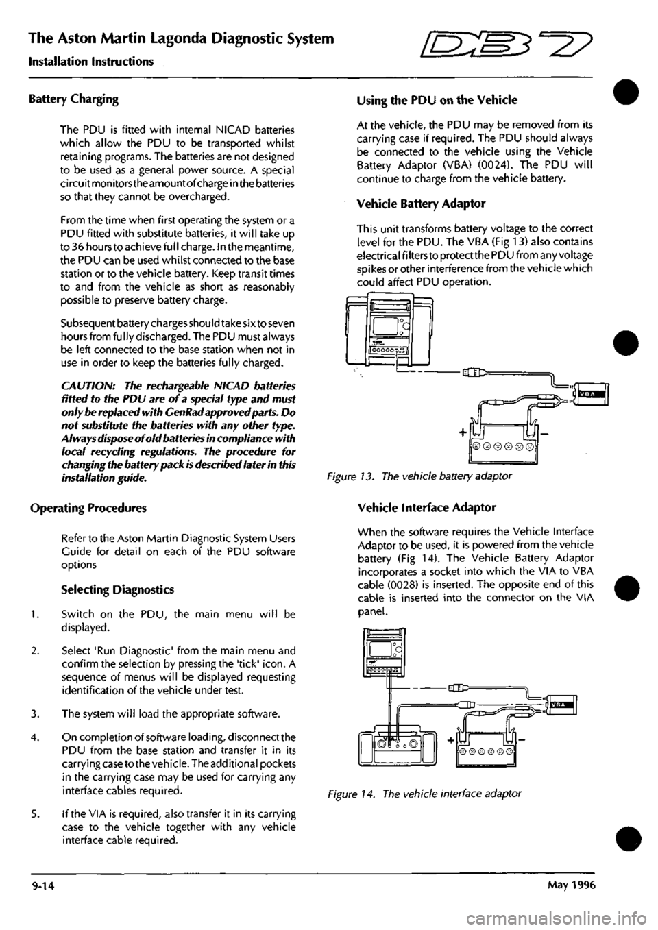
level for the PDU. The VBA (Fig 13) also contains
electrical filters to protect the PDU from any voltage
spikes or other interference from the vehicle which
could affect PDU operation.
f=l
a
OOOOOQS.fl
-dlD:
Figure 13. The vehicle battery adaptor
Vehicle Interface Adaptor
When the software requires the Vehicle Interface
Adaptor to be used, it is powered from the vehicle
battery (Fig 14). The Vehicle Battery Adaptor
incorporates a socket into which the VIA to VBA
cable (0028) is inserted. The opposite end of this
cable is inserted into the connector on the VIA
panel.
_a
hOOOOQpH"
-CIC=
=dD
n
S
© ® ® ® © ©
Figure 14. The vehicle interface adaptor
9-14 May 1996
Page 366 of 421

r^ ' ^ ^ The Aston Martin Lagonda Diagnostic System
Installation Instructions
Finishing the Test
When data analysis is finished, switch off the PDU
and disconnect it from the vehicle. Store the PDU
and cables in the carrying case and refit the case to
the base station.
Connect the PDU to the base station using cable
0064.
The base station will keep the PDU batteries
fully charged at all times (Fig 15).
Figure 15. PDU connected for recharging
Care of the Equipment
CAUTION: With the exception of those parts
referred to in the Servicing and Maintenance
section, there are no user serviceable parts. All
servicing must be carried out by GenRad Service
Centres.
Switch offthe power before cleaningtheequipment.
The Aston Martin Diagnostic System should only
be cleaned using a non-abrasive, mild cleaning
agent. Dust and other particles should be lightly
brushed from the surface before
cleaning.
Cleaning
agent should be applied to a soft lint-free cleaning
cloth and never directly to the unit. Do not soak the
cleaning cloth and take care not to allow cleaning
fluid to enter connectors.
CAUTION: Ifany liquid is spilt on theequipment,
switch off immediately.
Ensure
that the equipment
has
dried out completely before operating it again,
especially in connectors where fluid can lodge.
May 1996 9-15
Page 367 of 421
The Aston Martin Lagonda Diagnostic System
Installation Instructions ^7
Problem Solving
CAUTION: If any part of the
system
is damaged, do not use it. Call your local GenRad Service Centre immediately for
a substitute
part.
Refer to 'Parts Ordering'.
CAUTION: With the exception of
those
parts referred to in the Servicing and Maintenance section, there are no user
serviceable parts. All servicing must be carried out by GenRad Service Centres.
PDU Self-Test
The system self test routine should be run periodically even if there are no apparent problems with the system.
Running the system self-test will identify any problems before they impact on productivity.
If it is suspected that the system is operating incorrectly, run the PDU system self test option on the main menu).
If the system self test will not run, or the PDU will not switch on, the instructions in this section must be followed
carefully.
If one of the fol lowing test steps advises you to order or fit a new part, make a note of the test step, part number and
description. Then follow the parts ordering procedure later in this section.
Stepi
Connect the mains power to the base station. Is the green base station indicator illuminated?
YES - Go to step 4
NO - Go to step 2
Step 2
Check the mains supply, then check the mains
lead.
Is
the mains lead faulty?
YES - Renew the mains
lead.
NO - Go to step 3
Step 3
Remove the electronic module from the base station.
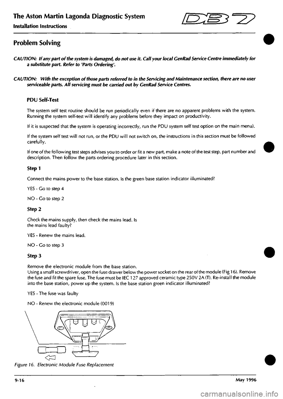
Using a small screwdriver, open the fuse drawer below the power socket on the rear of the module (Fig 16). Remove
the fuse and fit the spare fuse. The fuse must be lEC 127 approved ceramic type 250V 2A (T). Re-install the module
into the base station, power up the system. Is the base station green indicator illuminated?
YES - The fuse was faulty
NO - Renew the electronic module (0019)
Figure 16. Electronic Module Fuse Replacement
9-16 May 1996
Page 368 of 421
^^?
The Aston Martin Lagonda Diagnostic System
Installation Instructions
Step 4
Connect the mains power to the base station. Is the base station red indicator illuminated?
YES - Go to step 5
NO - Renew the electronic module (0019)
Steps
Switch off the PDU and disconnect
al I
cables. Set up the PDU to charge from the left charge socket on the base station
using one of the PDU to base station cables. Is the PDU charge indicator (Fig 1-5) illuminated.
YES - Go to step 9
NO - Go to step 6
Step 6
Set up the PDU to charge from the right socket on the base station using the same PDU to base station cable. Is the
PDU charge indicator (Fig 1-5) illuminated.
YES - Co to step 8
NO - Go to step 7
Step 7
Using the VBA, connect the PDU to a charged vehicle battery. Is the PDU charge indicator illuminated?
YES - Go to step 8
NO - Renew the PDU (001 7)
Steps
Switch off the PDU and disconnect all cables. Connect the PDU to the base station left connector using the second
PDU to base station cable (0064). Is the PDU charge indicator illuminated?
YES - The first PDU to base station cable (0064) is faulty, renew the cable.
NO - Renew the electronic module (0019).
Step 9
Switch on the PDU. Is the PDU power indicator (Fig 1-6) illuminated?
YES - Go to step 10.
NO - Renew the PDU (001 7).
Step 10
Is the PDU touch screen illuminated?
YES - Go to step 12.
NO - Go to step 11.
May 1996 9-17
Page 369 of 421
The Aston Martin Lagonda Diagnostic System
Installation Instructions -=2?
Step 11
Adjust the contrast control. Is the PDU touch screen illuminated?
YES - Co to step 12
NO - Renew the PDU (0017)
Step 12
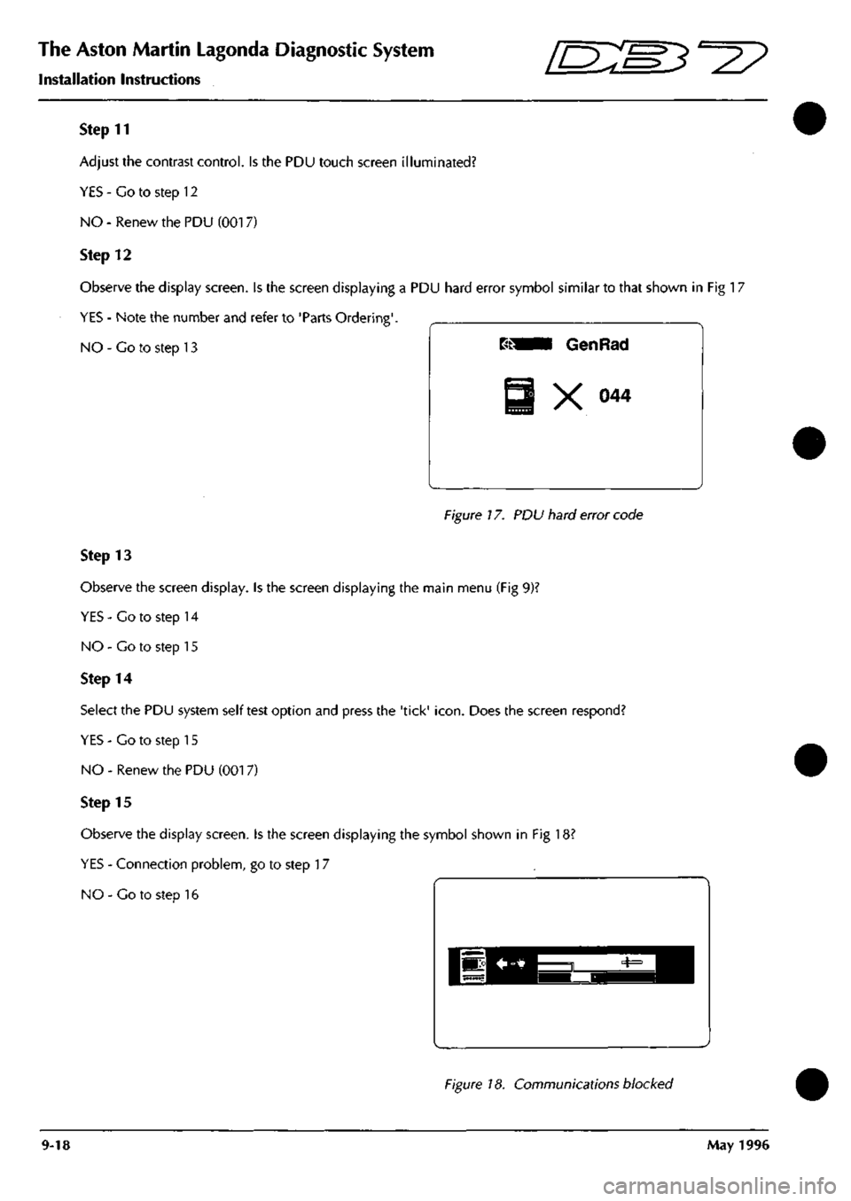
Observe the display screen. Is the screen displaying a PDU hard error symbol similar to that shown in Fig 17
YES - Note the number and refer to 'Parts Ordering'.
NO - Co to step 13
Figure 17. PDU hard error code
Step 13
Observe the screen display. Is the screen displaying the main menu (Fig 9)?
YES-Co to step 14
NO - Go to step 15
Step 14
Select the PDU system self test option and press the 'tick'
icon.
Does the screen respond?
YES - Co to step 15
NO - Renew the PDU (001 7)
Step 15
Observe the display screen. Is the screen displaying the symbol shown in Fig 18?
YES - Connection problem, go to step 17
NO - Co to step 16
Figure 18. Communications blocked
9-18 May 1996
Page 370 of 421
^^
The Aston Martin Lagonda Diagnostic System
Installation Instructions
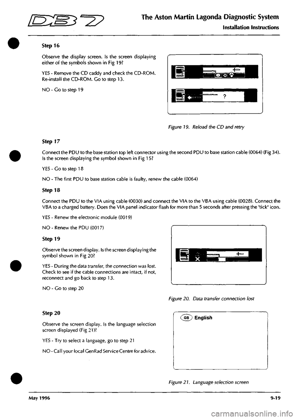
Step 16
Observe the display screen. Is the screen displaying
either of the symbols shown in Fig 19?
YES - Remove the CD caddy and check the CD-ROM.
Re-install the CD-ROM. Go to step 13.
NO - Co to step 19
Figure 19. Reload the CD and retry
Step 17
Connect the PDU to the base station top left connector using the second PDU to base station cable (0064) (Fig 34).
Is the screen displaying the symbol shown in Fig 15?
YES - Go to step 18
NO - The first PDU to base station cable is faulty, renew the cable (0064)
Step 18
Connect the PDU to the VIA using cable (0030) and connect the VIA to the VBA using cable (0028). Connect the
VBA to a charged battery. Does the VIA panel indicator flash for more than 5 seconds after pressing the 'tick'
icon.
YES - Renew the electronic module (0019)
NO - Renew the PDU (001 7)
Step 19
Observe the screen display. Is the screen displaying the
symbol shown in Fig 20?
YES - During the data transfer, the connection was lost.
Check to see if the cable connections are intact, if not,
reconnect and go back to step 13.
NO - Go to step 20
Figure 20. Data transfer connection lost
Step 20
Observe the screen display, is the language selection
screen displayed (Fig 21)?
YES - Try to select a language, go to step 21
NO-Call your local GenRad Service Centre for advice.
(^G?) English
Figure 2
7.
Language selection screen
May 1996 9-19