ASTON MARTIN V8 VANTAGE 2010 Workshop Manual
Manufacturer: ASTON MARTIN, Model Year: 2010, Model line: V8 VANTAGE, Model: ASTON MARTIN V8 VANTAGE 2010Pages: 947, PDF Size: 43.21 MB
Page 941 of 947

Service Bulletin SB-17-0298
February 2009 Page 4 of 5
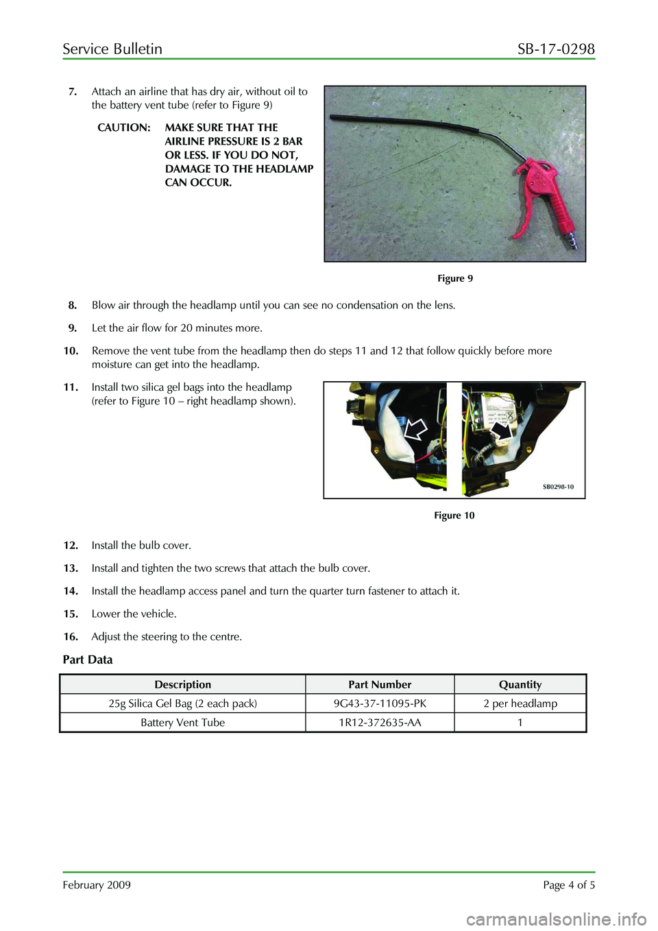
7. Attach an airline that has dry air, without oil to
the battery vent tube (refer to Figure 9)
CAUTION: MAKE SURE THAT THE
AIRLINE PRESSURE IS 2 BAR
OR LESS. IF YOU DO NOT,
DAMAGE TO THE HEADLAMP
CAN OCCUR.
Figure 9
8. Blow air through the headlamp until you can see no condensation on the lens.
9. Let the air flow for 20 minutes more.
10. Remove the vent tube from the headlamp then do steps 11 and 12 that follow quickly before more
moisture can get into the headlamp.
11. Install two silica gel bags into the headlamp
(refer to Figure 10 – right headlamp shown).
Figure 10
12. Install the bulb cover.
13. Install and tighten the two screws that attach the bulb cover.
14. Install the headlamp access panel and turn the quarter turn fastener to attach it.
15. Lower the vehicle.
16. Adjust the steering to the centre.
Part Data
Description Part Number Quantity
25g Silica Gel Bag (2 each pa ck) 9G43-37-11095-PK 2 per headlamp
Battery Vent Tube 1R12-372635-AA 1
Page 942 of 947

Service Bulletin SB-17-0298
February 2009 Page 5 of 5
Warranty Data
DBS and DB9, Coupe and Volante
Description Time Allowed Labour Code
Headlamp Condensation Drying Procedure – The
two sides 0.9 hrs. 17.01.BG
Headlamp Condensation Drying Procedure – One
Side 0.45 hrs. 17.01.BH
Vantage Coupe and Roadster
Description Time Allowed Labour Code
Headlamp Condensation Drying
Procedure – The two sides. 1.0 hrs. 17.01.BG
Headlamp Condensation Drying
Procedure – One Side 0.5 hrs. 17.01.BH
If you have any queries related to th
is Service Bulletin, please contact: Aston Martin Technical Services on:
+44 (0) 1926 644720 or facsimile: +44 (0) 1926 644733.
E-mail: [email protected]
. Or contact your After Sales Manager.
The English version of this Service Bulletin is written in Simplified Technical English to ASD STE-100™.
Page 943 of 947

SB0286V2
December 2009 Page 1 of 5
SERVICE BULLETIN
To: All Dealers
For the attention of: Service Manager/After Sales Manager
Please copy to: The Dealer Principal
Aston Martin Technician(s)
The Parts Manager
Reference
SB0286V2
Issued:
25 December 2009
Model: All Models
VIN Range: All
Subject: Rear Lamp Assembly Condensation Removal and
Repair Procedure Page 1 of 5
Reason for Version 2 of this Service Bulletin (SB0286)
Version 2 of this Service Bulletin has been issued to change the criteria for the quantity of water in the rear lamp,
before you change the lamp. Amendments to this document have a black line against them in the left-side
margin. Please destroy all copies of SB0286 that you have and replace them with this Service Bulletin SB0286V2.
Reason for this Service Bulletin
This Service Bulletin has been issued to give a procedure to dry out and repair a rear lamp assembly (lamp) that
has condensation inside. If a rear lamp has condensation inside, do the Workshop Procedure that follows:
Note: If there is moisture inside the lamp then there must be some damage.
Note: Before you do the Workshop Procedure you must make sure that the lamp unit operates correctly
because it is possible that water can have caused a shor t in the circuitry. It is also possible that if the
unit does not operate correctly, this drying out procedure can
repair the problem.
Workshop Procedure
1. Do a check of the operation of the lamp.
2. If two or more functions of the lamp do not operate correctly, install a new lamp.
3. Do a check for moisture in the rear lamp. If you can s ee water in the rear lamp that is not condensation on
the lens, install a new lamp.
CAUTION: WHEN YOU WORK ON THE LAMP MAKE SURE TH AT IT IS ON A PROTECTIVE SURFACE TO
PREVENT DAMAGE.
4. Remove the rear lamp assembly (Refer to the Workshop Manual procedure 17.02.AA (Left Side) or
17.02.AB (Right Side)).
5. If you do not replace the lamp because of the conditions in steps 2 or 3, do the procedure that follows to
dry the lamp.
Page 944 of 947

Service Bulletin SB0286V2
December 2009 Page 2 of 5
6. On the bottom of the lamp, make a mark for
the centre-point of the hole. The hole must be
40mm from the outside edge and at the centre
of the area shown in Figure 1.
Figure 1
CAUTION: WHEN YOU DRILL THE HOLE AT STEP 7, DO NOT DRILL THROUGH INTO THE LAMP
UNIT MORE THAN 10 MM. IF YOU DO, DAMAGE TO THE INTERNAL FITTINGS CAN
OCCUR.
7. Use a sharp 12 to 13 mm drill bit to drill a hole
at the position marked in Step 6. Drill slowly
and carefully to make sure that no swarf goes
into the lamp unit (Refer to Figure 2).
Figure 2
8 Turn the lamp unit to let the water drain out of the hole.
8. Find the location of the water leak (see the
example in Figure 3). Refer to ‘ Water Leak
Locations ’ after this Workshop Procedure for
the usual crack or split locations.
Figure 3
Page 945 of 947

Service Bulletin SB0286V2
December 2009 Page 3 of 5
Note: The location of the water leak can be difficult to find.
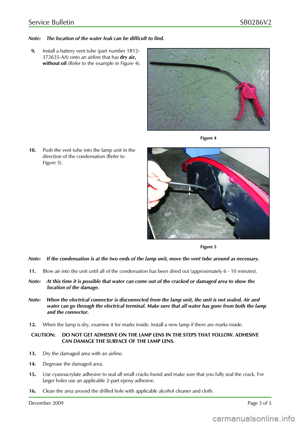
9. Install a battery vent tube (part number 1R12-
372635-AA) onto an airline that has dry air,
without oil (Refer to the example in Figure 4).
Figure 4
10. Push the vent tube into the lamp unit in the
direction of the condensation (Refer to
Figure 5).
Figure 5
Note: If the condensation is at the two ends of the la mp unit, move the vent tube around as necessary.
11. Blow air into the unit until all of the condensati on has been dried out (approximately 6 - 10 minutes).
Note: At this time it is possible that water can come out of the cracked or damaged area to show the
location of the damage.
Note: When the electrical connector is disconnected from the lamp unit, the unit is not sealed. Air and
water can go through the electrical terminal. Make sure that all water has gone from both the lamp
and the connector.
12. When the lamp is dry, examine it for marks inside. Install a new lamp if there are marks inside.
CAUTION: DO NOT GET ADHESIVE ON THE LAMP LENS IN THE STEPS THAT FOLLOW. ADHESIVE
CAN DAMAGE THE SURFACE OF THE LAMP LENS.
13. Dry the damaged area with an airline.
14. Degrease the damaged area.
15. Use cyanoacrylate adhesive to seal all small cracks fo und and make sure that you fully seal the crack. For
larger holes use an applicab le 2-part epoxy adhesive.
16. Clean the area around the drilled hole with applicable alcohol cleaner and cloth.
Page 946 of 947

Service Bulletin SB0286V2
December 2009 Page 4 of 5
17. Apply the adhesive patch (part number 4G43-
L20220-AA) to seal the hole (refer to Figure 6).
Figure 6
CAUTION: INSTALL NEW FOAM SEALS ON THE ATTACHMENT SCREWS WHEN YOU DO THE STEP
THAT FOLLOWS. IF YOU DO NOT, WATER CAN LEAK INTO THE VEHICLE.
18. Install the rear lamp assembly (Refer to the Work shop Manual procedure 17.02.AA (Left Side) or 17.02.AB
(Right Side).
Water Ingress Locations
Possible areas include:
• A crack in the lens under the infi ll panel (Figure 7 and Figure 8).
• Cracks in the housing around the mounting points (It em A, Figure 9), rub-through on the edge of the
lens (Item B, Figure 9) and lens /housing separation because of lo ad between the lens and the panel
(Figure 10).
Figure 7
Figure 8
Page 947 of 947

Service Bulletin SB0286V2
December 2009 Page 5 of 5
Figure 9
Figure 10
Parts Data
Description Part Number Quantity
Battery Vent Tube 1R12-372635-AA 1
Adhesive Sealing Patch 4G43-L20220-AA 1
Warranty Data
DB9 Coupe and Volante
Description Time Allowed Labour Code
Rear Lamp Unit – Left Side - Drying
Procedure 0.8 17.03.AC
Rear Lamp Unit – Right Side -
Drying Procedure 0.8 17.03.AD
V8 Vantage and Roadster
Description Time Allowed Labour Code
Rear Lamp Unit – Le
ft Side - Drying
Procedure 0.65 17.03.AC
Rear Lamp Unit – Right Side -
Drying Procedure 0.70 17.03.AD
DBS
Description Time Allowed Labour Code
Rear Lamp Unit – Le
ft Side - Drying
Procedure 0.8 17.03.AC
Rear Lamp Unit – Right Side -
Drying Procedure 0.8 17.03.AD
A
B
If you have any queries related to th
is Service Bulletin, please contact: Aston Martin Technical Services on:
+44 (0) 1926 644720 or facsimile: +44 (0) 1926 644733.
E-mail: [email protected]
. Or contact your After Sales Manager.
The English version of this Service Bulletin is written in Simplified Technical English to ASD STE-100™.