ASTON MARTIN V8 VANTAGE 2010 Workshop Manual
Manufacturer: ASTON MARTIN, Model Year: 2010, Model line: V8 VANTAGE, Model: ASTON MARTIN V8 VANTAGE 2010Pages: 947, PDF Size: 43.21 MB
Page 901 of 947

Aston Martin V8 Vantage 2009 MY EOBD DocumentationAston Martin/Ford Confidential
Component/ System Fault Code Monitor Strategy
Description Malfunction Criteria Threshold Parameter Secondary Parameters Entry Parameters Time Required DTC
StorageMIL Illumin-
ation
TPPC chip failure in
PCM P0606 TPPC chip to CPU
communication fault Number of attempts > 1
Continuous Footnote a) Footnote c)
Engine rpm > 1000 rpmEngine coolant temp > 15 deg C
(> 60 deg F)Continuous Footnote a) Footnote c)
Sensor signal voltage < 1.22 volts or > 3.42 volts
Engine load > 0.7 * 100% or < 0.2 *
100%
Time with sensor out of
range > 3.0 sec
Time with low throttle
voltage at TPPC or PCM >= 0.176 seconds
Sensor signal voltage < 0.2 volts
Time with high throttle
voltage at TPPC or PCM >= 0.176 seconds
Sensor signal voltage > 4.87 volts
Time with low throttle
voltage at TPPC or PCM >= 0.176 seconds
Sensor signal voltage < 0.08 volts
Time with high throttle
voltage at TPPC or PCM >= 0.176 seconds
Sensor signal voltage > 4.80 volts
Time with correlation
failure from the TPPC or
PCM or Equizzer >= 240 sec
Magnitude of the
difference of the relative
readings of the sensor
signal voltage > 0.073 volts
(6.533deg)
P2104 ETC FMEM – forced idle Two or three pedal sensors failed, throttle
plate stuck>= 100 to 400 msec None
N/AContinuous Footnote a) Footnote c)
P2105 ETC FMEM – forced engine shutdown Equizzer detected fault >= 16 to 960 msec None
N/AContinuous Footnote a) Footnote c)
P2106 ETC FMEM – pedal-follower mode Sensor fault: MAF, one
TP, CKP, TSS, OSS, stuck
throttle, throttle actuator
circuit fault>= 16 to 960 msec None
N/AContinuous Footnote a) Footnote c)
P2110 ETC FMEM – default throttle angle Two TPs failed; TPPC
detected fault>= 600 to 800 msec None
N/AContinuous Footnote a) Footnote c)
P2111
(Stuck Open) Functional test
Desired throttle angle vs.
actual throttle angle
measured in a rolling
average routine during
throttle tip-in> 3.5 degrees None
N/AContinuous Footnote a) Footnote c)
P2112
(Stuck Closed) Functional test
Desired throttle angle vs.
actual throttle angle
measured in a rolling
average routine during
throttle tip-out> 3.5 degrees None
N/AContinuous Footnote a) Footnote c)
P2107 TPPC processor check Internal processor test, lost communication with
main CPU>= 60 msec None N/A Continuous Footnote a) Footnote c)
P2100 Circuit check Throttle actuator circuit open>= 1750 msec None N/A Continuous Footnote a) Footnote c)
P2101 Range check Throttle actuator range/performance test,
throttle plate angle does
not followed commanded
angle>= 500 msec None N/A Continuous Footnote a) Footnote c)Electronic Throttle Control
Rationality check
None
TP Sensor
Inconsistent With
MAF Sensor
TP Sensor A/B
Correlation
TP Sensor 'B' Input
Out Of Range P0122 (Low)
P0123 (High)
Range check
Rationality check vs. MAF
input
Throttle Actuator
Control System
Throttle Plate
Position Controller
(TPPC)
Throttle Actuator
Control Motor P2135
N/AContinuous Footnote a) Footnote c) Footnote c)
None
P0222 (Low) Range check N/AContinuous Footnote a)
P0223 (High)
TP Sensor 'A' Input
Out Of Range
None
N/A Continuous Footnote a) Footnote c)
P0068
13
Page 902 of 947

Aston Martin V8 Vantage 2009 MY EOBD DocumentationAston Martin/Ford Confidential
At 98% DC:
At 0% DC:
FNMISPCT_97
Load RPM700 950 1500 2000 2500 3000 4000 5000 6000 7500
0.10.20 0.20 0.20 0.20 0.20 0.20 0.17 0.12 0.12 0.100.150.20 0.20 0.20 0.20 0.20 0.20 0.17 0.12 0.12 0.100.20.20 0.20 0.20 0.20 0.20 0.20 0.17 0.12 0.12 0.100.30.20 0.20 0.20 0.20 0.20 0.16 0.15 0.11 0.12 0.090.40.20 0.20 0.20 0.20 0.16 0.14 0.12 0.10 0.10 0.090.50.20 0.20 0.20 0.16 0.16 0.14 0.12 0.09 0.09 0.080.70.20 0.20 0.20 0.16 0.14 0.13 0.12 0.08 0.08 0.080.90.20 0.20 0.20 0.16 0.14 0.13 0.12 0.08 0.08 0.08
Misfire Monitor Time Delay Since Engine Start Up = 0 seconds + FNMISACT valu
eFNMISACTACT ( degC )-40 -29 -7 60 66 93
output_axis [s]180 180 0 0 0 0
FNMISOK_97
Load RPM 700 950 1500 2000 2500 3000 4000 5000 6000 7500 0.10.043 0.043 0.001 0.043 0000000.150.614 0.614 0.833 0.614 1 0.444 0 0 0 00.21 1 1 1 1 1 0.474 0.029 0 00.31 1 1 1 1 1 1 0.885 0.474 0.0430.4111111111 0.6140.511111111110.711111111110.91111111111
FN_TCSTRT (sec)
TCSTRT [degC] -28.8 -17.7 -6.6 10 26.6 37.7 46.1 82.2 93.3 output_axis [s] 12093581086555
FN384 (RPM)ECT [degC] -160 -17.7 10 15.5 32.2 123.3
output_axis [RPM] 200 200 250 250 250 250
FN202 ("H20)SYS DELPR (kPa)29.09 33.86 40.63 54.18 67.72 88.04
output_axis [kPa]6.77 6.97 9.41 16.52 26.71 47.74
FN654S (sec)
TCSTRT [degC] -160 -34.4 -23.3 -15 -6.6 10 48.8 123.3
output_axis [s] 1400 1400 1150 990 870 670
340 340
FNECTWUT (degF)TCSTRT [degC] -160 -9.4 -6.6 123.3
output_axis [degC] 71.1 71.1 77.2 77.2
FNWUT_LDTCSTRT [degC] -160 -17.7 -6.6 123.3
output_axis 0.3 0.3 0.3 0.3
FNWUT_VS (mph)TCSTRT [degC] -160 -17.7 10 26.6 123.3
output_axis [mph] 20 20 25 30 30
FNCAM_ACT_FKDEG CRK0 0.2 2 2.8 60
output_axis [mph] 0.01 0.04 0.4 1 1
CAM_RANGE_SENSDEG CRK -50 -30 -15 0 20
output_axis 22222
DMTL total small leak threshold = TDMKLGTF+TDMKLGTF
DMTL total small leak threshold = TDMKLGTF+TDMKLGTF+FN_KFTDSTAB
TDMKLGTF
GVTAF0.15 0.25 0.5 0.75 0.85
output_axis [s] 115 125 150 188 210
TDMGLGTFGVTAF0.15 0.25 0.5 0.75 0.85
output_axis [s] 0.1 0.1 0.1 0.1 0.1
FIPTGLRIPTGH [A]01234
5678
output_axis [s] 0.5 0.5 0.5 0.5 0.5 0.5 0.5 0.5 0.5
FIPTGLRIPTGH [A]01234
5678
output_axis [s] 11111
1111
FN_KFTDSTABGVTAF/IPTGH01234
5678
0.15 76 76 76 76 76 76 76 76 76
0.25 105 105 105 105 105 105 105 105 105
0.35 135 135 135 135 135 135 135 135 135
0.45 167 167 167 167 167 167 167 167 167
0.55 205 205 205 205 205 205 205 205 205
0.65 262 262 262 262 262 262 262 262 262
0.75 318 318 318 318 318 318 318 318 318
0.85 380 380 380 380 380 380 380 380 380
Signal circuit voltage threshold calculation for DTC P0443
[(42 x Battery voltage) - 150] x 5.0/1024 volts
[(32 x Battery voltage) - 200] x 5.0/1024 volts
14
Page 903 of 947
2009 MY OBD-II Documentation4.7L, Aston Martin V8 VantageAston Martin / Ford Confidential
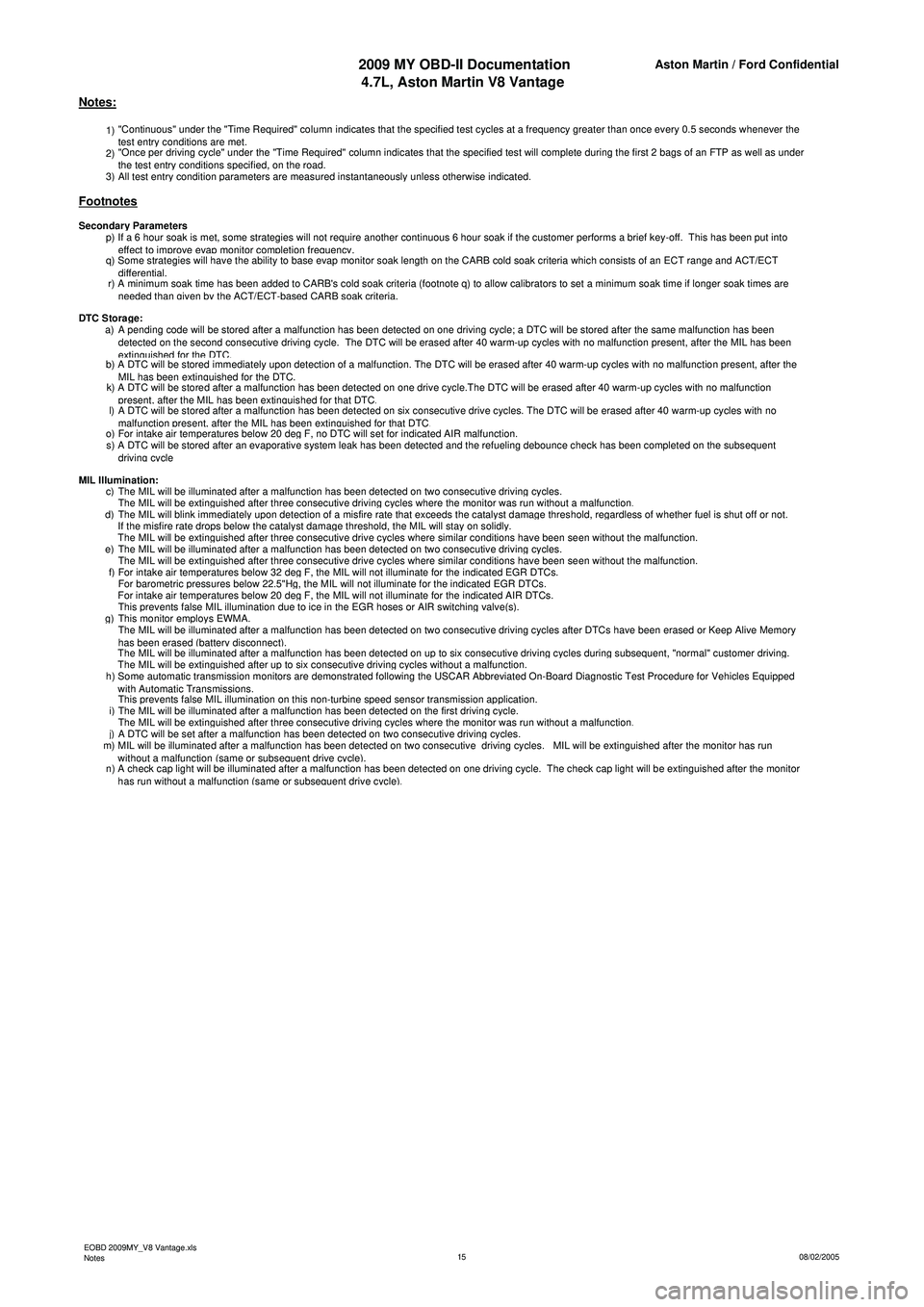
1) "Continuous" under the "Time Required" column indicates that the specified test cycles at a frequency greater than once every 0.5 seconds whenever the
test entry conditions are met.
2) "Once per driving cycle" under the "Time Required" column indicates that the specified test will complete during the first 2 bags of an FTP as well as under
the test entr
y conditions specified, on the road.
3)All test entry condition parameters are measured instantaneously unless otherwise indicated.
p) If a 6 hour soak is met, some strategies will not require another continuous 6 hour soak if the customer performs a brief key-off. This has been put into
effect to improve evap monitor completion frequency.
q) Some strategies will have the ability to base evap monitor soak length on the CARB cold soak criteria which consists of an ECT range and ACT/ECT
differential.
r) A minimum soak time has been added to CARB's cold soak criteria (footnote q) to allow calibrators to set a minimum soak time if longer soak times are
n
eeded than given by the ACT/ECT-based CARB soak criteria.
a) A pending code will be stored after a malfunction has been detected on one driving cycle; a DTC will be stored after the same malfunction has been detected on the second consecutive driving cycle. The DTC will be erased after 40 warm-up cycles with no malfunction present, after the MIL has been
extinguished for the DTC.b) A DTC will be stored immediately upon detection of a malfunction. The DTC will be erased after 40 warm-up cycles with no malfunction present, after the MIL has been extinguished for the DTC.k) A DTC will be stored after a malfunction has been detected on one drive cycle.The DTC will be erased after 40 warm-up cycles with no malfunction present, after the MIL has been extinguished for that DTC.l) A DTC will be stored after a malfunction has been detected on six consecutive drive cycles. The DTC will be erased after 40 warm-up cycles with no malfunction present, after the MIL has been extinguished for that DTC.o)For intake air temperatures below 20 deg F, no DTC will set for indicated AIR malfunction.
s) A DTC will be stored after an evaporative system leak has been detected and the refueling debounce check has been completed on the subsequent
driving cycle
c)The MIL will be illuminated after a malfunction has been detected on two consecutive driving cycles.
The MIL will be extinguished after three consecutive driving cycles where the monitor was run without a malfunction.d)The MIL will blink immediately upon detection of a misfire rate that exceeds the catalyst damage threshold, regardless of whether fuel is shut off or not.
If the misfire rate drops below the catalyst damage threshold, the MIL will stay on solidly.
The MIL will be extinguished after three consecutive drive cycles where similar conditions have been seen without the malfunction.e)The MIL will be illuminated after a malfunction has been detected on two consecutive driving cycles.
The MIL will be extinguished after three consecutive drive cycles where similar conditions have been seen without the malfunction.f)For intake air temperatures below 32 deg F, the MIL will not illuminate for the indicated EGR DTCs.
For barometric pressures below 22.5"Hg, the MIL will not illuminate for the indicated EGR DTCs.
For intake air temperatures below 20 deg F, the MIL will not illuminate for the indicated AIR DTCs.
This prevents false MIL illumination due to ice in the EGR hoses or AIR switching valve(s).g)This monitor employs EWMA.
The MIL will be illuminated after a malfunction has been detected on two consecutive driving cycles after DTCs have been erased or Keep Alive Memory
h
as been erased (battery disconnect).
The MIL will be illuminated after a malfunction has been detected on up to six consecutive driving cycles during subsequent, "normal" customer driving.
The MIL will be extinguished after up to six consecutive driving cycles without a malfunction.
h) Some automatic transmission monitors are demonstrated following the USCAR Abbreviated On-Board Diagnostic Test Procedure for Vehicles Equipped
wi
th Automatic Transmissions.
This prevents false MIL illumination on this non-turbine speed sensor transmission application.
i)The MIL will be illuminated after a malfunction has been detected on the first driving cycle.
The MIL will be extinguished after three consecutive driving cycles where the monitor was run without a malfunction.j)A DTC will be set after a malfunction has been detected on two consecutive driving cycles.
m) MIL will be illuminated after a malfunction has been detected on two consecutive driving cycles. MIL will be extinguished after the monitor has run
wi
thout a malfunction (same or subsequent drive cycle).
n) A check cap light will be illuminated after a malfunction has been detected on one driving cycle. The check cap light will be extinguished after the monitor
h
as run without a malfunction (same or subsequent drive cycle).
MIL Illumination:
Notes:
Footnotes
Secondary Parameters
DTC Stora
ge:
EOBD 2009MY_V8 Vantage.xls
Notes 08/02/2005
15
Page 904 of 947

V8 4.7L EOBD Documentation
ASM Gearbox Tables
Page 905 of 947
Aston Martin V8 Vantage2009MY OBDII Documentation 4.7L Aston Martin Confidential
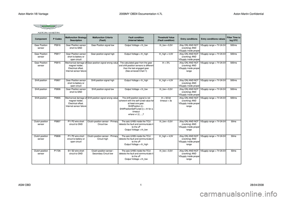
Component P CodesMalfunction Strategy
Description Malfunction Criteria
(Fault) Fault condition
(Internal labels) Threshold Value
(Fault condition) Entry conditions Entry conditions values Filter Time to
log DTC
Gear Position sensor P0916 Gear Position sensor
short to GND Gear Position signal low Output Voltage < th_low th_low = 0,5V (Key ON) AND NOT
(cranking) AND
VSupply inside prope
r VSupply range = 7V-24.5V 500ms
Gear Position sensor P0917 Gear Position sensor
short to battery or open circuit Gear position signal high Output Voltage > th_high
th_high = 4,5V (Key ON) AND NOT
(cranking) AND
VSupply inside proper VSupply range = 7V-24.5V 500ms
Gear Position sensor P0915 Mechanical damage o
f
magnet holder;
Electrical offset.
Internal sensor failure Gear position signal wrong value The calculated gear from the gear
and shift position sensors is different than the last engaged gear(See annexed Chart 1) th = 3% (Key ON) AND NOT
(cranking) AND
VSupply inside prope
r
range VSupply range = 7V-24.5V 500ms
Shift position P0907 Gear Position sensor short to battery or open circuit Shift position signal high Output Voltage > th_high
th_high = 4,5V (Key ON) AND NOT
(cranking) AND
VSupply inside proper VSupply range = 7V-24.5V 500ms
Shift position P0906 Gear Position sensor short to GNDShift position signal low
Output Voltage < th_low th_low = 0,5V (Key ON) AND NOT
(cranking) AND
VSupply inside proper VSupply range = 7V-24.5V 500ms
Shift position P0905 Mechanical damage o
f
magnet holder;
Electrical offset.
Internal sensor failure Shift position signal wrong value The shift position signal is not
coherent with the self tuned value fo
r
at least one gear.ShiftPosition (i) -
ShiftPositionSelfTuned (i) > th for a timeout
where i=1,2,…,7 th = 50 bit
timeout = 3s (Key ON) AND NOT
(cranking) AND
VSupply inside prope
r
range VSupply range = 7V-24.5V 500ms
Clutch position sensor P0807 P1/ P2 wire short
circuit to GND Clutch position sensor - Primary
Circuit low The asic UH05 inside the TCU
detects the fault and communicate it to the uP
Output Voltage < th_low th_low = 0,5V (Key ON) AND NOT
(cranking) AND
VSupply inside proper
range VSupply range = 7V-24.5V 50ms
Clutch position sensor P0808 P1/ P2 wire short
circuit to battery or open circuit Clutch position sensor - Primary
Circuit high The asic UH05 inside the TCU
detects the fault and communicate it to the uP
Output Voltage > th_high th_high = 4,5V (Key ON) AND NOT
(cranking) AND
VSupply inside proper
range VSupply range = 7V-24.5V 50ms
Clutch position sensor P173A S1/ S2 wire short
circuit to GND Clutch position sensor -
Secondary Circuit low The asic UH05 inside the TCU
detects the fault and communicate it to the uP
Output Voltage < th_low th_low = 0,5V (Key ON) AND NOT
(cranking) AND
VSupply inside proper
range VSupply range = 7V-24.5V 50ms
ASM OBD
128/04/2008
Page 906 of 947
Aston Martin V8 Vantage2009MY OBDII Documentation 4.7L Aston Martin Confidential
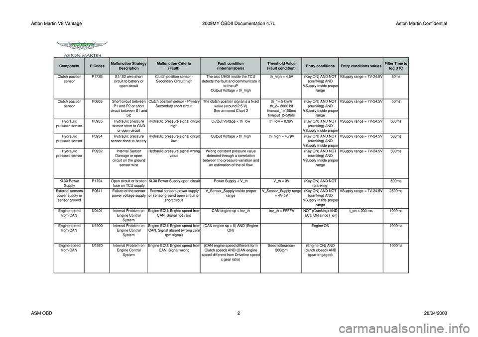
Component P CodesMalfunction Strategy
Description Malfunction Criteria
(Fault) Fault condition
(Internal labels) Threshold Value
(Fault condition) Entry conditions Entry conditions values Filter Time to
log DTCClutch position sensor P173B S1/ S2 wire short
circuit to battery or open circuit Clutch position sensor -
Secondary Circuit high The asic UH05 inside the TCU
detects the fault and communicate it to the uP
Output Voltage > th_high th_high = 4,5V (Key ON) AND NOT
(cranking) AND
VSupply inside prope
r
range VSupply range = 7V-24.5V 50ms
Clutch position sensor P0805 Short circuit between
P1 and P2 or short
circuit between S1 and S2 Clutch position sensor - Primary
Secondary short circuit The clutch position signal is a fixed
value (around 2.5 V)
See annexed Chart 2 th_1= 5 km/h
th_2= 2000 bit
timeout_1=100ms timeout_2=50ms (Key ON) AND NOT
(cranking) AND
VSupply inside proper
range VSupply range = 7V-24.5V 50ms
Hydraulic
pressure sensor P0935 Hydraulic pressure
sensor short to GND or open circuit Hydraulic pressure signal circuit
high Output Voltage < th_low th_low = 0,39V (Key ON) AND NOT
(cranking) AND
VSupply inside proper VSupply range = 7V-24.5V 500ms
Hydraulic
pressure sensor P0934 Hydraulic pressure
sensor short to battery Hydraulic pressure signal circuit
low Output Voltage > th_high th_high = 4,79V (Key ON) AND NOT
(cranking) AND
VSupply inside proper VSupply range = 7V-24.5V 500ms
Hydraulic
pressure sensor P0932 Internal Sensor
Damage or open
circuit on the ground sensor wire Hydraulic pressure signal wrong
value Wrong constant pressure value
detected through a correlation
between the pressure variation and an estimation of the oil flow (Key ON) AND NOT
(cranking) AND
VSupply inside proper
range VSupply range = 7V-24.5V 500ms
Kl.30 Power Supply P1794 Open circuit or broken
fuse on TCU supply Kl.30 Power Supply open circuit Power Supply < V_th
V_th = 3V (Key ON) AND NOT
(cranking) 500ms
External sensors power supply or sensor ground P0641 Failure of the sensor
power voltage supply External sensors power supply
or sensor ground open circuit or short circuit V_Sensor_Supply inside proper
range V_Sensor_Supply range
= 4V-5V (Key ON) AND NOT
(cranking) AND
VSupply inside proper
range VSupply range = 7V-24.5V 2500ms
Engine speed from CAN U0401 Internal Problem on
Engine Control System Engine ECU: Engine speed fro
m
CAN. Signal not valid
CAN engine sp = inv_th inv_th = FFFFh NOT (Cranking) AND
(ECU ON since t_on)t_on = 200 ms 1000ms
Engine speed from CAN U1900 Internal Problem on
Engine Control System Engine ECU: Engine speed fro
m
CAN. Signal absent (wrong zero
rpm signal) (CAN engine sp = 0) AND (Engine
ON) Engine ON 1000ms
Engine speed from CAN U1920 Internal Problem on
Engine Control System Engine ECU: Engine speed fro
m
CAN. Signal wrong
(CAN engine speed different form
Clutch speed) AND (CAN engine
speed different from Driveline speed x gear ratio) Seed tollerance=
500rpm (Engine ON) AND
(clutch closed) AND (gear engaged) 1000ms
ASM OBD
228/04/2008
Page 907 of 947
Aston Martin V8 Vantage2009MY OBDII Documentation 4.7L Aston Martin Confidential
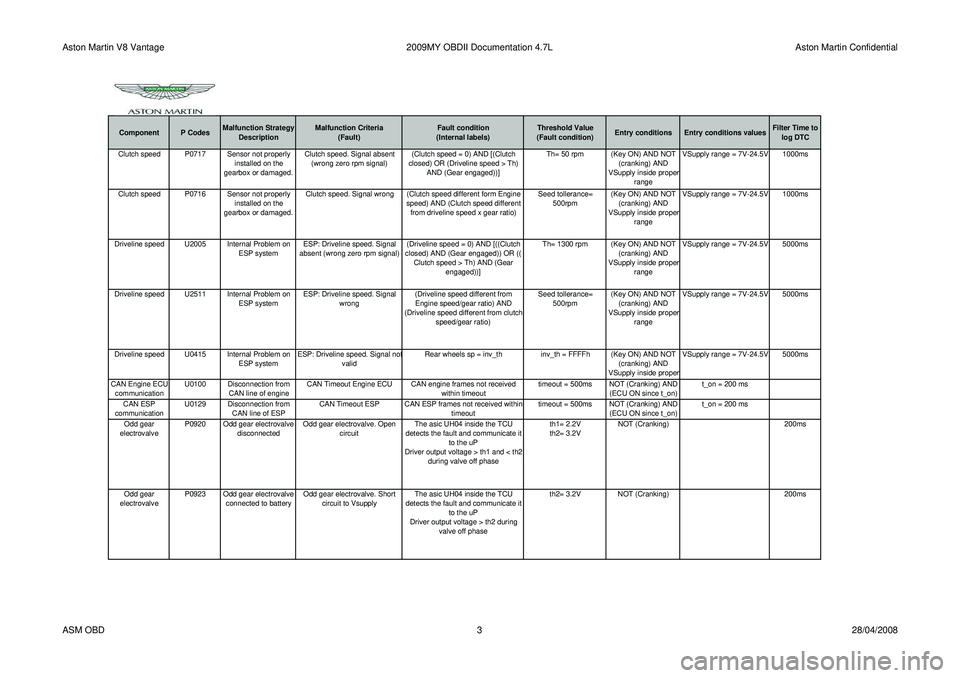
Component P CodesMalfunction Strategy
Description Malfunction Criteria
(Fault) Fault condition
(Internal labels) Threshold Value
(Fault condition) Entry conditions Entry conditions values Filter Time to
log DTCClutch speed P0717 Sensor not properly installed on the
gearbox or damaged. Clutch speed. Signal absent
(wrong zero rpm signal) (Clutch speed = 0) AND [(Clutch
closed) OR (Driveline speed > Th) AND (Gear engaged))] Th= 50 rpm (Key ON) AND NOT
(cranking) AND
VSupply inside prope
r
range VSupply range = 7V-24.5V 1000ms
Clutch speed P0716 Sensor not properly installed on the
gearbox or damaged. Clutch speed. Signal wrong (Clutch speed different form Engine
speed) AND (Clutch speed different from driveline speed x gear ratio) Seed tollerance=
500rpm (Key ON) AND NOT
(cranking) AND
VSupply inside proper
range VSupply range = 7V-24.5V 1000ms
Driveline speed U2005 Internal Problem on ESP systemESP: Driveline speed. Signal
absent (wrong zero rpm signal) (Driveline speed = 0) AND [((Clutch
closed) AND (Gear engaged)) OR (( Clutch speed > Th) AND (Gear engaged))] Th= 1300 rpm (Key ON) AND NOT
(cranking) AND
VSupply inside proper
range VSupply range = 7V-24.5V 5000ms
Driveline speed U2511 Internal Problem on ESP systemESP: Driveline speed. Signal
wrong (Driveline speed different from
Engine speed/gear ratio) AND
(Driveline speed different from clutch speed/gear ratio) Seed tollerance=
500rpm (Key ON) AND NOT
(cranking) AND
VSupply inside proper
range VSupply range = 7V-24.5V 5000ms
Driveline speed U0415 Internal Problem on ESP systemESP: Driveline speed. Signal no
t
valid Rear wheels sp = inv_th
inv_th = FFFFh (Key ON) AND NOT
(cranking) AND
VSupply inside prope
r VSupply range = 7V-24.5V 5000ms
CAN Engine ECU communication U0100 Disconnection from
CAN line of engine CAN Timeout Engine ECU CAN engine frames not received
within timeouttimeout = 500ms NOT (Cranking) AND
(ECU ON since t_on) t_on = 200 ms
CAN ESP
communication U0129 Disconnection from
CAN line of ESP CAN Timeout ESP CAN ESP frames not received within
timeouttimeout = 500ms NOT (Cranking) AND
(ECU ON since t_on) t_on = 200 ms
Odd gear
electrovalve P0920 Odd gear electrovalve
disconnected Odd gear electrovalve. Open
circuit The asic UH04 inside the TCU
detects the fault and communicate it to the uP
Driver output voltage > th1 and < th2 during valve off phase th1= 2.2V
th2= 3.2V
NOT (Cranking)
200ms
Odd gear
electrovalve P0923 Odd gear electrovalve
connected to battery Odd gear electrovalve. Short
circuit to Vsupply The asic UH04 inside the TCU
detects the fault and communicate it to the uP
Driver output voltage > th2 during valve off phase th2= 3.2V
NOT (Cranking) 200ms
ASM OBD 328/04/2008
Page 908 of 947
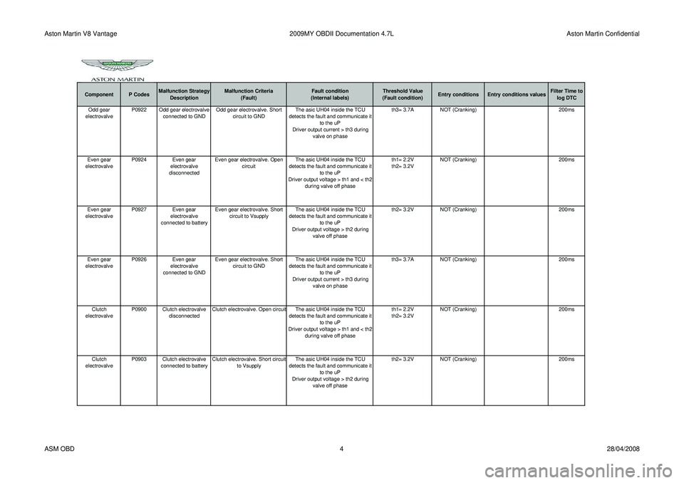
Aston Martin V8 Vantage2009MY OBDII Documentation 4.7L Aston Martin Confidential
Component P CodesMalfunction Strategy
Description Malfunction Criteria
(Fault) Fault condition
(Internal labels) Threshold Value
(Fault condition) Entry conditions Entry conditions values Filter Time to
log DTCOdd gear
electrovalve P0922 Odd gear electrovalve
connected to GND Odd gear electrovalve. Short
circuit to GND The asic UH04 inside the TCU
detects the fault and communicate it to the uP
Driver output current > th3 during valve on phase th3= 3.7A
NOT (Cranking) 200ms
Even gear
electrovalve P0924 Even gear
electrovalve
disconnected Even gear electrovalve. Open
circuit The asic UH04 inside the TCU
detects the fault and communicate it to the uP
Driver output voltage > th1 and < th2 during valve off phase th1= 2.2V
th2= 3.2V
NOT (Cranking)
200ms
Even gear
electrovalve P0927
Even gear
electrovalve
connected to battery Even gear electrovalve. Short
circuit to Vsupply The asic UH04 inside the TCU
detects the fault and communicate it to the uP
Driver output voltage > th2 during valve off phase th2= 3.2V
NOT (Cranking) 200ms
Even gear
electrovalve P0926 Even gear
electrovalve
connected to GND Even gear electrovalve. Short
circuit to GND The asic UH04 inside the TCU
detects the fault and communicate it to the uP
Driver output current > th3 during valve on phase th3= 3.7A
NOT (Cranking) 200ms
Clutch
electrovalve P0900 Clutch electrovalve
disconnected Clutch electrovalve. Open circuit The asic UH04 inside the TCU
detects the fault and communicate it to the uP
Driver output voltage > th1 and < th2 during valve off phase th1= 2.2V
th2= 3.2V
NOT (Cranking)
200ms
Clutch
electrovalve P0903 Clutch electrovalve
connected to battery Clutch electrovalve. Short circuit
to Vsupply The asic UH04 inside the TCU
detects the fault and communicate it to the uP
Driver output voltage > th2 during valve off phase th2= 3.2V
NOT (Cranking) 200ms
ASM OBD 428/04/2008
Page 909 of 947
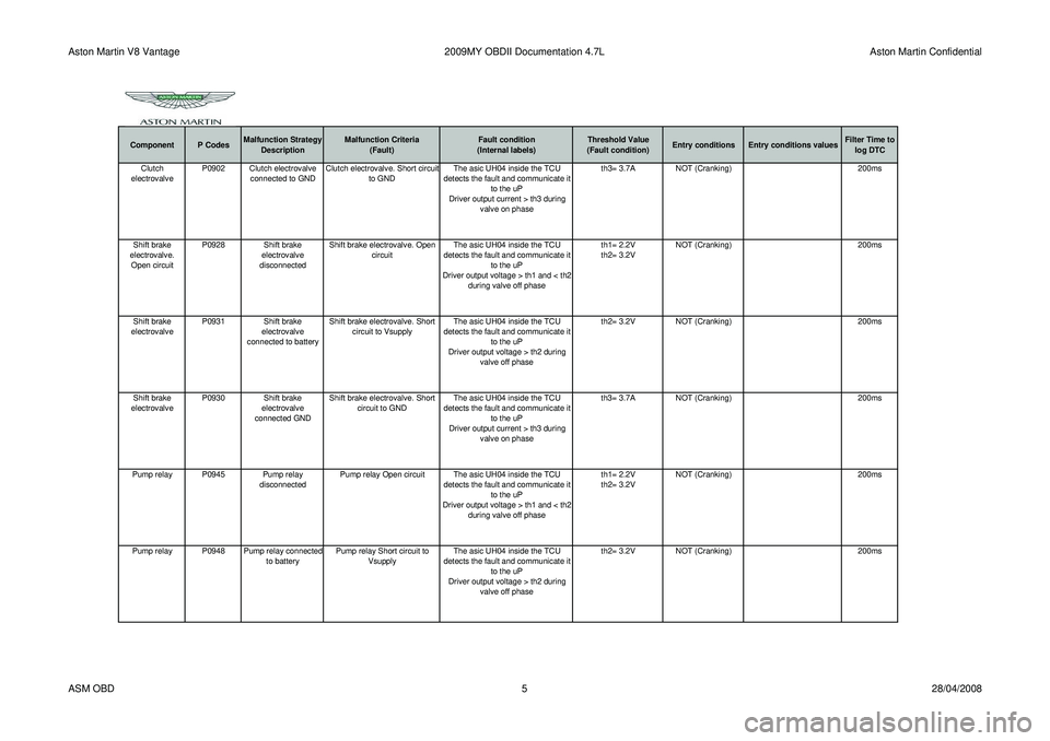
Aston Martin V8 Vantage2009MY OBDII Documentation 4.7L Aston Martin Confidential
Component P CodesMalfunction Strategy
Description Malfunction Criteria
(Fault) Fault condition
(Internal labels) Threshold Value
(Fault condition) Entry conditions Entry conditions values Filter Time to
log DTCClutch
electrovalve P0902 Clutch electrovalve
connected to GND Clutch electrovalve. Short circuit
to GND The asic UH04 inside the TCU
detects the fault and communicate it to the uP
Driver output current > th3 during valve on phase th3= 3.7A
NOT (Cranking) 200ms
Shift brake
electrovalve. Open circuit P0928 Shift brake
electrovalve
disconnected Shift brake electrovalve. Open
circuit The asic UH04 inside the TCU
detects the fault and communicate it to the uP
Driver output voltage > th1 and < th2 during valve off phase th1= 2.2V
th2= 3.2V
NOT (Cranking)
200ms
Shift brake
electrovalve P0931 Shift brake
electrovalve
connected to battery Shift brake electrovalve. Short
circuit to Vsupply The asic UH04 inside the TCU
detects the fault and communicate it to the uP
Driver output voltage > th2 during valve off phase th2= 3.2V
NOT (Cranking) 200ms
Shift brake
electrovalve P0930 Shift brake
electrovalve
connected GND Shift brake electrovalve. Short
circuit to GND The asic UH04 inside the TCU
detects the fault and communicate it to the uP
Driver output current > th3 during valve on phase th3= 3.7A
NOT (Cranking) 200ms
Pump relay P0945 Pump relay disconnectedPump relay Open circuit The asic UH04 inside the TCU
detects the fault and communicate it to the uP
Driver output voltage > th1 and < th2 during valve off phase th1= 2.2V
th2= 3.2V
NOT (Cranking)
200ms
Pump relay P0948 Pump relay connected to batteryPump relay Short circuit to
Vsupply The asic UH04 inside the TCU
detects the fault and communicate it to the uP
Driver output voltage > th2 during valve off phase th2= 3.2V
NOT (Cranking) 200ms
ASM OBD 528/04/2008
Page 910 of 947

Aston Martin V8 Vantage2009MY OBDII Documentation 4.7L Aston Martin Confidential
Component P CodesMalfunction Strategy
Description Malfunction Criteria
(Fault) Fault condition
(Internal labels) Threshold Value
(Fault condition) Entry conditions Entry conditions values Filter Time to
log DTCPump relay P0947 Pump relay connected GNDPump relay Short circuit to GND The asic UH04 inside the TCU
detects the fault and communicate it to the uP
Driver output current > th3 during valve on phase th3= 3.7A
NOT (Cranking) 200ms
Clutch system P186D Clutch or actuator or valve damagedClutch not opening before gear
shifting Clutch not open in a timeout timeout = 500ms (Gear shifting in
progress) AND
(Clutch opening
Gear Box system P1734 Mechanical or hydraulic problemGear Box. Disengage failed
(mechanical causes) Gear not disengaged in a timeout timeout = 500ms (Gear shifting phase)
AND (disengage phase)
Gear Box system P1701 Mechanical or hydraulic problemGear Box. Wrong gear
engagement The gear which is going to be
engaged is not the requested one (Gear shifting phase)
Hydraulic circuit P0868 Hydraulic leakage Hydraulic circuit. Pressure low Comparison between sensor pressure signal and threshold = f(oil temperature)
pressure < th Th= 25 bar @ -30°C
Th= 40 bar @120°C linear interpolation (Engine ON) AND
NOT (cranking) 200ms
Power grounds P1710 Power grounds. Disconnection both ground pins Power grounds. Disconnection
both ground pins The diagnosis is based on the batter
y
voltage modification during the
activation of the clutch electrovalve. Ubatt < Ubatt0 - DltUbatt Ubatt0 = Ubatt before
starting the testDltUbatt = 2,5V Wake-up phase
ASM OBD
628/04/2008