AUDI R8 2007 Repair Manual
Manufacturer: AUDI, Model Year: 2007, Model line: R8, Model: AUDI R8 2007Pages: 210, PDF Size: 8.1 MB
Page 61 of 210
Lights and vision59
Controls
Safety
Driving tips
General maintenance
Self-help
Technical data
Windscreen wipersWindscreen wipers
The windscreen wiper lever controls the windscreen
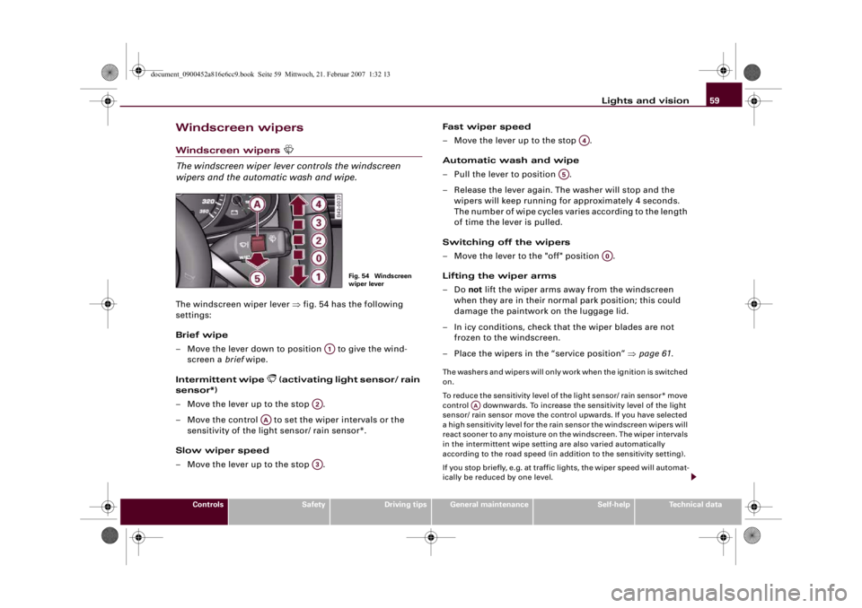
wipers and the automatic wash and wipe.The windscreen wiper lever ⇒fig. 54 has the following
settings:
Brief wipe
– Move the lever down to position to give the wind-
screen a brief wipe.
Intermittent wipe
(activating light sensor/ rain
sensor*)
– Move the lever up to the stop .
– Move the control to set the wiper intervals or the
sensitivity of the light sensor/ rain sensor*.
Slow wiper speed
– Move the lever up to the stop .Fast wiper speed
– Move the lever up to the stop .
Automatic wash and wipe
– Pull the lever to position .
– Release the lever again. The washer will stop and the
wipers will keep running for approximately 4 seconds.
The number of wipe cycles varies according to the length
of time the lever is pulled.
Switching off the wipers
– Move the lever to the "off" position .
Lifting the wiper arms
–Do not lift the wiper arms away from the windscreen
when they are in their normal park position; this could
damage the paintwork on the luggage lid.
– In icy conditions, check that the wiper blades are not
frozen to the windscreen.
–Place the wipers in the “service position” ⇒page 61.
The washers and wipers will only work when the ignition is switched
on.
To reduce the sensitivity level of the light sensor/ rain sensor* move
control downwards. To increase the sensitivity level of the light
sensor/ rain sensor move the control upwards. If you have selected
a high sensitivity level for the rain sensor the windscreen wipers will
react sooner to any moisture on the windscreen. The wiper intervals
in the intermittent wipe setting are also varied automatically
according to the road speed (in addition to the sensitivity setting).
If you stop briefly, e.g. at traffic lights, the wiper speed will automat-
ically be reduced by one level.
Fig. 54 Windscreen
wiper lever
A1
A2
AA
A3
A4
A5
A0
AA
document_0900452a816e6cc9.book Seite 59 Mittwoch, 21. Februar 2007 1:32 13
Page 62 of 210
Lights and vision 60The windscreen washer jets are heated when the ignition is
switched on.
When the lights are switched on you should only pull the lever
briefly to wash the windscreen, otherwise the headlight washers
will also be activated. This will use an unnecessary amount of fluid
from the reservoir.
WARNING
•
Poor visibility can cause accidents. Always ensure that the
wiper blades are in good condition ⇒page 62, “Changing wiper
blades”.
•
The light sensor/ rain sensor* is only intended to assist the
driver. The driver is still obliged to manually operate the wind-
screen wipers and the lights as required depending on visibility.
•
Do not use water-repellent coatings on the windscreen. In bad
visibility conditions such as light rain, low sun or when driving at
night these coatings can cause increased dazzle, which is a
serious safety hazard. Such coatings can also cause the wiper
blades to judder.Caution
•
In icy conditions, always check that the wiper blades are not
frozen to the glass before using the wiper for the first time. If you
switch on the wipers when the wiper blades are frozen to the glass,
this could damage both the wiper blades and the wiper motor.
•
Make sure you switch off the windscreen wiper system (lever in
position "0") before you use an automatic car wash. This will avoid
inadvertent triggering of the wipers and possible damage to the
wiper system.Note
•
Check that the washer fluid reservoir is full before starting a long
journey. Filling the reservoir ⇒page 164.
•
Worn or dirty wiper blades can cause smearing on the glass
which can also impair the effectiveness of the light sensor/ rain
sensor*. Please check the wiper blades regularly.
•
If you leave the windscreen wiper lever set to the intermittent
wipe function when the ignition is switched off, the light sensor/
rain sensor* will not be activated until you reach a road speed of at
least 6 km/h.
•
Applies to vehicles with light sensor/ rain sensor: If the wind-
screen wipers have been activated manually and it is raining, the
automatic headlights* will come on ⇒page 53, “Automatic (sensor-
controlled) headlights”. In the daytime the headlights will automat-
ically go off again once the wipers are switched off. The automatic
headlights* function is only available if the light switch is in the
“AUTO” position ⇒page 53, fig. 47.
Headlight washer systemWith the lights switched on, operate the automatic wind-
screen wash and wipe ⇒page 59, fig. 54 , and keep the
lever pulled towards you for at least 1 second.The headlight washer jets come out of the bumper automatically
(under water pressure).
Clean off stubborn dirt (insects, etc.) from the lenses at regular
intervals, for instance when stopping for fuel.
To ensure that the system works properly in winter, keep the nozzle
holders free of snow and remove any ice with a de-icer spray.
A5
document_0900452a816e6cc9.book Seite 60 Mittwoch, 21. Februar 2007 1:32 13
Page 63 of 210
Lights and vision61
Controls
Safety
Driving tips
General maintenance
Self-help
Technical data
Service position
The wiper blades can only be replaced when the wiper
arms are in the service position.The windscreen wipers will only function if the luggage lid
is completely closed.
Moving the wiper blades into the service
position
– In icy conditions, check that the wiper blades are not
frozen to the windscreen.
– Switch on the ignition.
– Move the windscreen wiper lever to position 0.
– Press the button repeatedly until the DISPLAY
TYPE menu appears in the driver information system
display.
– Use the rocker switch and the button to select
SET > WIPERS > FRONT > SERVICE POSITION ON. The
wiper arms will move into the service position.Returning the wiper blades to their normal park
position
– Make sure that the wiper blades are resting on the wind-
screen.
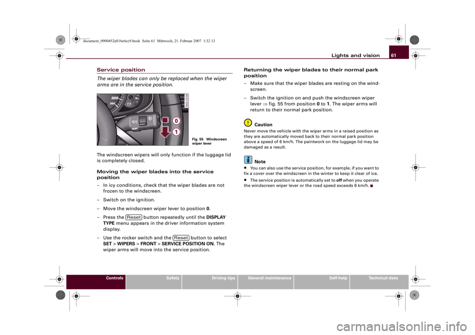
– Switch the ignition on and push the windscreen wiper
lever ⇒fig. 55 from position 0 to 1. The wiper arms will
return to their normal park position.
Caution
Never move the vehicle with the wiper arms in a raised position as
they are automatically moved back to their normal park position
above a speed of 6 km/h. The paintwork on the luggage lid may be
damaged as a result.
Note
•
You can also use the service position, for example, if you want to
fix a cover over the windscreen in the winter to keep it clear of ice.
•
The service position is automatically set to off when you operate
the windscreen wiper lever or the road speed exceeds 6 km/h.
Fig. 55 Windscreen
wiper lever
Reset
Reset
document_0900452a816e6cc9.book Seite 61 Mittwoch, 21. Februar 2007 1:32 13
Page 64 of 210
Lights and vision 62Changing wiper blades
Good wiper blades are essential for clear vision.Taking off the wiper blade
– Place the wipers in the service position ⇒page 61.
– Lift the wiper arm away from the glass.
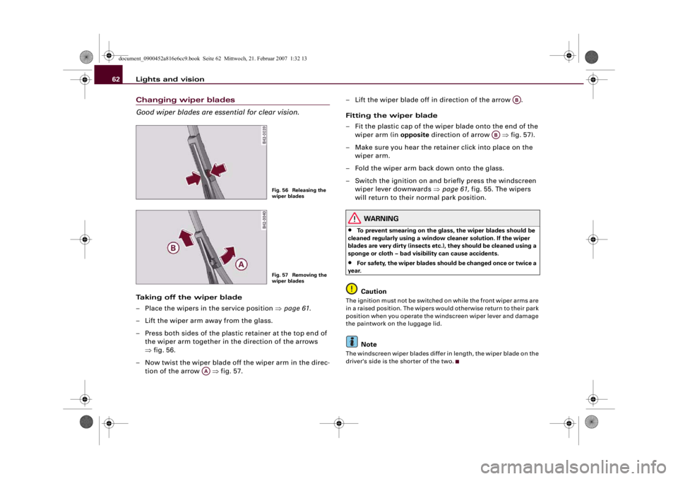
– Press both sides of the plastic retainer at the top end of
the wiper arm together in the direction of the arrows
⇒fig. 56.
– Now twist the wiper blade off the wiper arm in the direc-
tion of the arrow ⇒fig. 57.– Lift the wiper blade off in direction of the arrow .
Fitting the wiper blade
– Fit the plastic cap of the wiper blade onto the end of the
wiper arm (in opposite direction of arrow ⇒fig. 57).
– Make sure you hear the retainer click into place on the
wiper arm.
– Fold the wiper arm back down onto the glass.
– Switch the ignition on and briefly press the windscreen
wiper lever downwards ⇒page 61, fig. 55. The wipers
will return to their normal park position.
WARNING
•
To prevent smearing on the glass, the wiper blades should be
cleaned regularly using a window cleaner solution. If the wiper
blades are very dirty (insects etc.), they should be cleaned using a
sponge or cloth – bad visibility can cause accidents.
•
For safety, the wiper blades should be changed once or twice a
year.Caution
The ignition must not be switched on while the front wiper arms are
in a raised position. The wipers would otherwise return to their park
position when you operate the windscreen wiper lever and damage
the paintwork on the luggage lid.
Note
The windscreen wiper blades differ in length, the wiper blade on the
driver's side is the shorter of the two.
Fig. 56 Releasing the
wiper bladesFig. 57 Removing the
wiper blades
AA
AB
AB
document_0900452a816e6cc9.book Seite 62 Mittwoch, 21. Februar 2007 1:32 13
Page 65 of 210
Lights and vision63
Controls
Safety
Driving tips
General maintenance
Self-help
Technical data
Rear-view mirrorsManual anti-dazzle adjustmentNormal setting
– Push the lever at the bottom of the mirror away from you.
Anti-dazzle setting
– Pull the lever at the bottom of the mirror towards you.Applies to vehicles: with automatic anti-dazzle adjustment for interior mirrorAutomatic anti-dazzle interior mirror
The automatic anti-dazzle function can be switched on
and off as desired.Switching off anti-dazzle function
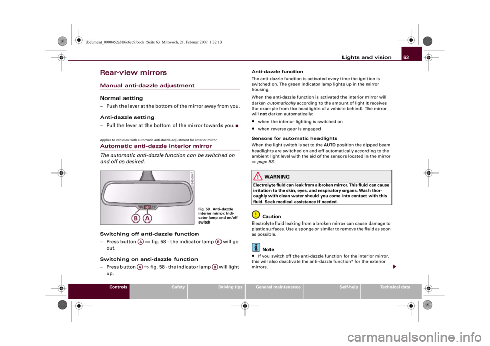
– Press button ⇒fig. 58 - the indicator lamp will go
out.
Switching on anti-dazzle function
– Press button ⇒fig. 58 - the indicator lamp will light
up.
Anti-dazzle function
The anti-dazzle function is activated every time the ignition is
switched on. The green indicator lamp lights up in the mirror
housing.
When the anti-dazzle function is activated the interior mirror will
darken automatically according to the amount of light it receives
(for example from the headlights of a vehicle behind). The mirror
will not darken automatically:•
when the interior lighting is switched on
•
when reverse gear is engaged
Sensors for automatic headlights
When the light switch is set to the AUTO position the dipped beam
headlights are switched on and off automatically according to the
ambient light level with the aid of the sensors located in the mirror
⇒page 53.
WARNING
Electrolyte fluid can leak from a broken mirror. This fluid can cause
irritation to the skin, eyes, and respiratory organs. Wash thor-
oughly with clean water should you come into contact with this
fluid. Seek medical assistance if needed.
Caution
Electrolyte fluid leaking from a broken mirror can cause damage to
plastic surfaces. Use a sponge or similar to remove the fluid as soon
as possible.
Note
•
If you switch off the anti-dazzle function for the interior mirror,
this will also deactivate the anti-dazzle function* for the exterior
mirrors.
Fig. 58 Anti-dazzle
interior mirror: Indi-
cator lamp and on/off
switch
AA
AB
AA
AB
document_0900452a816e6cc9.book Seite 63 Mittwoch, 21. Februar 2007 1:32 13
Page 66 of 210
Lights and vision 64•
The automatic anti-dazzle function will only work properly if
there are no objects preventing light from reaching the interior
mirror.
•
Do not attach any stickers to the windscreen in front of the
sensors, as this would interfere with the operation of the automatic
headlights and the automatic anti-dazzle function for the mirror.
Exterior mirrors
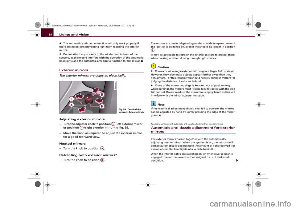
The exterior mirrors are adjusted electrically.Adjusting exterior mirrors
– Turn the adjuster knob to position (left exterior mirror)
or position (right exterior mirror) ⇒fig. 59.
– Move the knob as required to adjust the exterior mirror
for a good rearward view.
Heated mirrors
– Turn the knob to position .
Retracting both exterior mirrors*
– Turn the knob to position .
The mirrors are heated depending on the outside temperature until
the ignition is switched off, even if the knob is no longer in position
.
It may be advisable to retract* the exterior mirrors to protect them
when parking or when driving through tight spaces.
Caution
•
Convex or wide-angle exterior mirrors give a larger field of vision.
However, they also make objects appear further away than they
actually are. For this reason, you should not rely on these mirrors for
judging the distance of vehicles behind.
•
If one of the mirror housings is knocked out of position (e.g.
when parking), the mirrors must first be fully retracted with the elec-
tric control. Do not readjust the mirror housing by hand, as this will
interfere with the mirror adjuster function.Note
If the electrical adjustment should ever fail to operate, the mirrors
can be adjusted by hand by lightly pressing the edge of the mirror
glass.Applies to vehicles: with automatic anti-dazzle adjustment for exterior mirrorsAutomatic anti-dazzle adjustment for exterior mirrorsThe exterior mirrors darken together with the automatically
adjusting interior mirror. When the ignition is on, the mirrors will
darken automatically according to the amount of light received (for
example from the headlights of a vehicle behind).
When the interior lights are switched on, or when reverse gear is
engaged, the mirrors revert to their original (i.e. not darkened)
condition.
Fig. 59 Detail of the
armrest: Adjuster knob
AL
AR
AAAB
AA
document_0900452a816e6cc9.book Seite 64 Mittwoch, 21. Februar 2007 1:32 13
Page 67 of 210
Lights and vision65
Controls
Safety
Driving tips
General maintenance
Self-help
Technical data
WARNING
Electrolyte fluid can leak from a broken mirror. This fluid can cause
irritation to the skin, eyes, and respiratory organs. Wash thor-
oughly with clean water should you come into contact with this
fluid. Seek medical assistance if needed.
Caution
Electrolyte fluid leaking from a broken mirror can cause damage to
the paintwork or plastic surfaces. Use a sponge or similar to remove
the fluid as soon as possible.
Note
•
If you switch off the automatic anti-dazzle function for the inte-
rior mirror, this will also deactivate the automatic anti-dazzle func-
tion for the exterior mirrors.
•
The automatic anti-dazzle function will only work properly if
there are no objects preventing light from reaching the interior
mirror.
Digital compassApplies to vehicles: with digital compassActivating and deactivating the compass
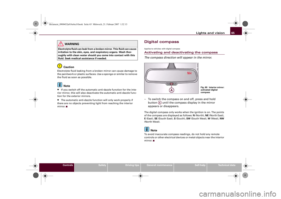
The compass direction will appear in the mirror.– To switch the compass on and off, press and hold
button until the compass display in the mirror
appears or disappears.The digital compass only works when the ignition is on. The points
of the compass are displayed as follows: N (North), NE (North East),
E (East), SE (South East), S (South), SW (South West), W (West), NW
(North West).
Note
To avoid inaccurate compass readings, do not hold any remote
controls or other electrical devices or metal objects near the interior
mirror.
Fig. 60 Interior mirror:
activated digital
compass
AA
document_0900452a816e6cc9.book Seite 65 Mittwoch, 21. Februar 2007 1:32 13
Page 68 of 210
Lights and vision 66Applies to vehicles: with digital compassSetting the correct compass calibration zone
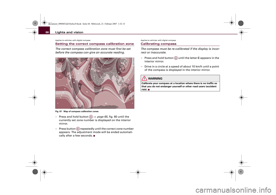
The correct compass calibration zone must first be set
before the compass can give an accurate reading.Fig. 61 Map of compass calibration zones– Press and hold button ⇒page 65, fig. 60 until the
currently set zone number is displayed on the interior
mirror.
– Press button repeatedly until the correct zone number
appears. The adjustment mode will be ended automati-
cally after a few seconds.
Applies to vehicles: with digital compassCalibrating compass
The compass must be re-calibrated if the display is incor-
rect or inaccurate.– Press and hold button until the letter C appears in the
interior mirror.
– Drive in a circle at a speed of about 10 km/h until a point
of the compass is displayed in the interior mirror.
WARNING
Calibrate your compass at a location where there is no traffic so
that you do not endanger yourself or other road users (accident
risk).
AA
AA
AA
document_0900452a816e6cc9.book Seite 66 Mittwoch, 21. Februar 2007 1:32 13
Page 69 of 210
Seats and storage67
Controls
Safety
Driving tips
General maintenance
Self-help
Technical data
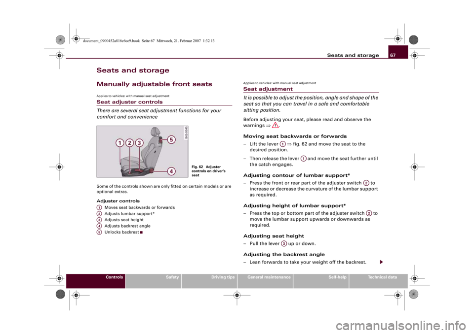
Seats and storageManually adjustable front seatsApplies to vehicles: with manual seat adjustmentSeat adjuster controls
There are several seat adjustment functions for your
comfort and convenienceSome of the controls shown are only fitted on certain models or are
optional extras.
Adjuster controls
Moves seat backwards or forwards
Adjusts lumbar support*
Adjusts seat height
Adjusts backrest angle
Unlocks backrest
Applies to vehicles: with manual seat adjustmentSeat adjustment
It is possible to adjust the position, angle and shape of the
seat so that you can travel in a safe and comfortable
sitting position.Before adjusting your seat, please read and observe the
warnings ⇒.
Moving seat backwards or forwards
– Lift the lever ⇒fig. 62 and move the seat to the
desired position.
– Then release the lever and move the seat further until
the catch engages.
Adjusting contour of lumbar support*
– Press the front or rear part of the adjuster switch to
increase or decrease the curvature of the lumbar support
as required.
Adjusting height of lumbar support*
– Press the top or bottom part of the adjuster switch to
move the lumbar support upwards or downwards as
required.
Adjusting seat height
– Pull the lever up or down.
Adjusting the backrest angle
– Lean forwards to take your weight off the backrest.
Fig. 62 Adjuster
controls on driver's
seat
A1A2A3A4A5
A1
A1
A2A2
A3
document_0900452a816e6cc9.book Seite 67 Mittwoch, 21. Februar 2007 1:32 13
Page 70 of 210
Seats and storage 68
– Turn the adjuster wheel to set the angle of the back-
rest as required.
Unlocking backrest
– Push the handle upwards.
– Fold the backrest forwards
WARNING
•
Never adjust the driver's seat when the vehicle is moving - this
could lead to an accident.
•
Be careful when adjusting the seat angle. Careless or uncon-
trolled use of the seat adjustment can cause injuries.
•
Do not drive with the backrests of the front seats reclined too
far as otherwise the seat belt and airbag could fail to restrain the
wearer properly in an accident, possibly leading to injury.
•
For safety reasons the front seat backrests must be locked
while driving.
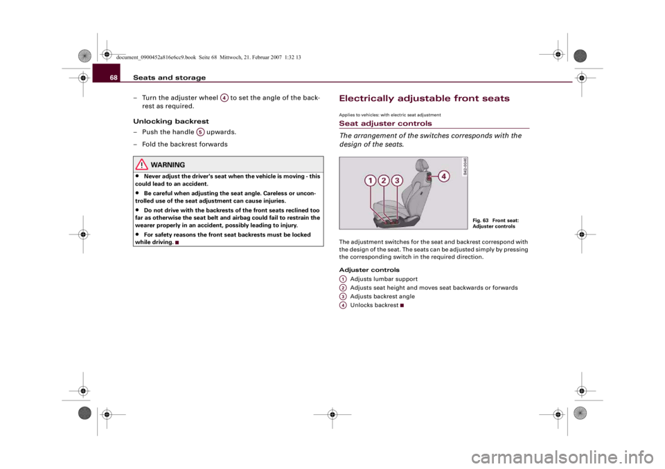
Electrically adjustable front seatsApplies to vehicles: with electric seat adjustmentSeat adjuster controls
The arrangement of the switches corresponds with the
design of the seats.The adjustment switches for the seat and backrest correspond with
the design of the seat. The seats can be adjusted simply by pressing
the corresponding switch in the required direction.
Adjuster controls
Adjusts lumbar support
Adjusts seat height and moves seat backwards or forwards
Adjusts backrest angle
Unlocks backrest
A4
A5
Fig. 63 Front seat:
Adjuster controls
A1A2A3A4
document_0900452a816e6cc9.book Seite 68 Mittwoch, 21. Februar 2007 1:32 13