AUDI TT ROADSTER 2018 Owners Manual
Manufacturer: AUDI, Model Year: 2018, Model line: TT ROADSTER, Model: AUDI TT ROADSTER 2018Pages: 310, PDF Size: 46.95 MB
Page 281 of 310
Cl co .... N ,....
N ...... 0 ,....
Vl co
-Always stor e damaged whee l, jack and too ls
securely in the luggage compartment. Oth erwise, in an accident or sudden maneuver
they could fly forward, caus ing injury to pas
sengers in the vehicle .
Spare tire
General information
Applies to: veh icles wit h space -saving spa re t ire (compact
spa re t ire)
A U DI
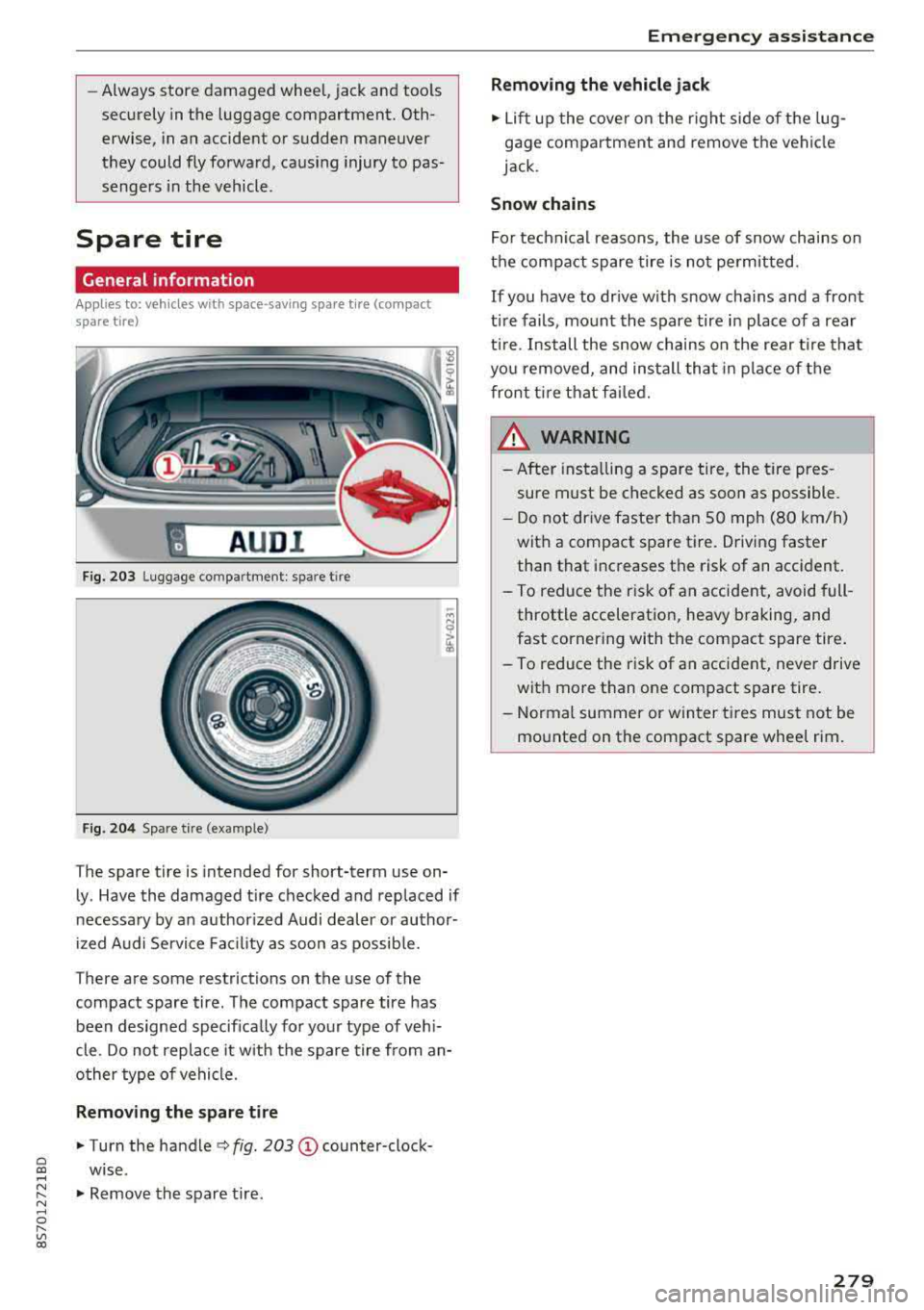
Fig. 203 Lugg age co mpar tment : spar e tir e
F ig . 204 Sp are t ire (ex ample)
The spare tire is intended for short-term use on
ly . Have the damaged t ire checked and replaced if
necessary by an author ized Audi dealer or author
i zed A udi Service Fac ility as soon as possib le.
T here are some restrictions on the use of the
compact spare tire . The compact spare tire has
been designed specifica lly for your type of veh i
cle . Do not replace it w ith the spare tire from an
o ther type of vehicle.
Removing the spare tire
.,. Turn the handle c::> fig . 203 (D counter-clock
wise.
.,. Remove the spare tire .
Emergen cy as sis tanc e
Removing the vehicle jack
.,. Lift up the cover on the right side of the lug
gage compartment and remove the vehicle
jack.
Snow chains
For technical reasons, the use of snow chains on
the compact spare tire is not pe rmit ted.
If you have to dr ive with snow chains and a front
t ire fails , mount the spare tire in place of a rear
t ir e. Install the snow chains on the rear t ire that
yo u removed, and ins tall that in place of the
front t ire that fai led.
_&, WARNING ..
- After insta lling a spare tire, the tire pres
sure must be checked as soon as possible .
- D o not dr ive faster than 50 mph (80 km/h)
with a compact spare tire. Driving faster
than that inc reases the risk of an accident.
- To reduce the r isk of an accident, avoid full
throttle acceleration, heavy braking, and
fast corner ing with the compact spare tire .
-
- To reduce the risk of an accident, neve r drive
with more than one compact spare tire .
- Normal summer or winter tires must not be mounted on the compact spare wheel rim.
279
Page 282 of 310
Fuses and bulbs
Fuses and bulbs
Electrical fuses
Replacing fuses
A fuse that has blown will have metal strips that
have burned through.
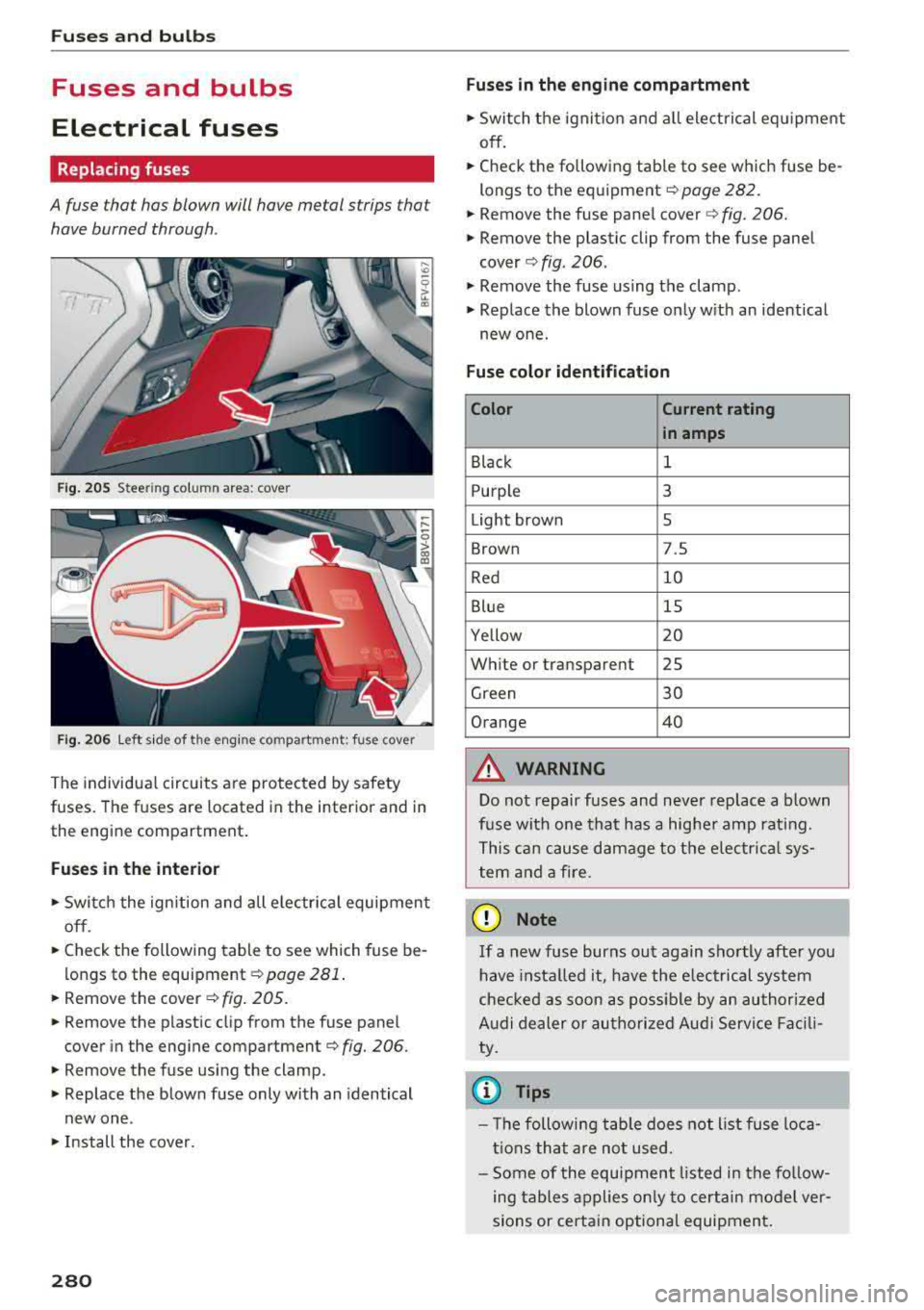
Fig. 20 5 Steering column area: cover
F ig. 20 6 Left side of the e ngine compartment: fuse cover
The individu al circuits are pro tec ted by safety
fuses. The fuses are located in the inter ior and in
the engine compartment .
Fuses in the interior
., Switch the ignition and all e lectr ica l equipment
off.
.. Check the following table to see which fuse be
l ongs to the
equipment ¢ page 281.
.. Remove the cover ¢ fig. 205.
.. Remove the plastic cl ip from the fuse panel
cover in the engine
compartment¢ fig. 206 .
.. Remove the fuse using the clamp.
., Replace the blow n fu se only with an identical
new one .
., Install the cover.
280
Fuses in the engine compartment
.. Switch the ignit io n and all electrical eq uipment
off .
.. Check the following table to see which fuse be
longs to th e eq uipment
¢page 282.
.. Remove the fuse pane l cover c> fig . 206.
.. Remove the plastic clip from the fuse panel
cover ¢ fig. 206 .
., Remove the fuse us ing the clamp .
.. Replace the blown fuse on ly w ith an ident ical
new one.
Fuse color identification
Color Current rating
in amps
Black 1
Purple 3
Light brown 5
Brown 7.S
Red
10
Blue 15
Yellow 20
Wh ite or transparent 25
Green 30
Orange 40
A WARNING
D o not repair fuses and neve r rep lace a blown
f u se with one tha t has a hig her amp rat ing.
T his ca n ca use damage to the e lectr ica l sys
tem and a fire .
(D Note
If a new fuse burns out again sho rtly after you
h ave insta lled it, have the e lectrical system
che cked as soon as possible by an au thori zed
A udi de aler or au tho riz ed Audi Service Fac ili
ty .
0) Tips
- Th e followi ng t able does not list fuse loca
t ions tha t are not used.
- Some of the e quipment listed in the fo llow
ing tables applies on ly to certain mo del ver
sions or certa in option al equipmen t.
Page 283 of 310
Cl co .... N ,....
N ...... 0 ,....
Vl co
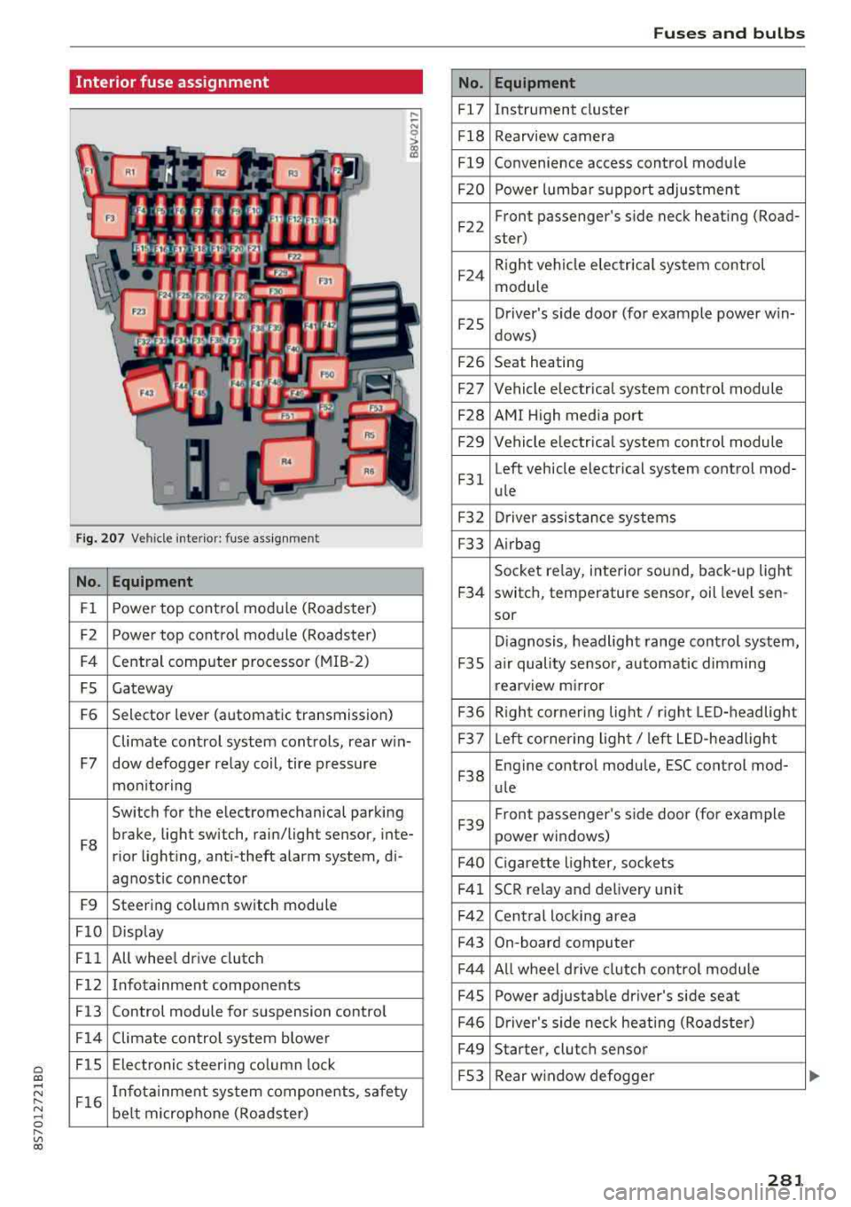
Interior fuse assignment
Fig. 207 Vehicle interior: fuse assignmen t
No. Equipment
Fl Power top cont
rol module (Roadster)
F2 Power top control module (Roadster)
F4 Central computer processor (MIB
-2)
FS Gateway
F6 Selector lever (automatic transmission)
Climate control system controls, rear w in-
F7 dow defogger relay coil, tire pressure
mon itoring
Switch for the electromechanical parking
F8 brake, light switch, rain/light sensor, inte-
rior lighting, anti -theft alarm system, di -
agnostic connector
F9 Steering column switch module
FlO Display
Fll All whee
l drive clutch
F12 Infotainment components
F13 Control module for suspension control
F14 Climate control system blowe r
FlS Electronic steering column
lock
F16 I
nfotainment system components, safety
be lt microphone (Roadster)
No.
Fl7
F1 8
Fl9
F20
F 22
F24
F 25
F 26
F 27
F28
F2 9
F 31
F3 2
F33
F 34
F 35
F36
F37
F3 8
F39
F40
F41
F 42
F43
F44
F45
F46
F49
F S3
Fuses and bulbs
Equipment
Instrument cluster
Rearview camera
Convenience access control module
Power lumbar support adjustment
Front passenger's side neck heating (Road-
ster)
R ight vehicle electrica l system control
module
Driver's s ide door (for example power w in-
dows)
Seat heating
Vehicle electrical system control module
AMI High media port
Vehicle e lectr ical system control module
Left vehicle electrical system contro l mod-
ule
Driver assistance systems
Airbag
Socket relay, inte rior sound , back-up light
switch, temperature sensor, oil leve l sen -
sor
Diagnosis, headlight range control system,
a ir quality sensor, automatic dimming
rearview mirror
R ight cornering light/ right LED-headlight
L eft cornering light/ left LED-headlight
Engine control module, ESC control mod-
ule
Front passenger's side door (for example
power windows)
C igarette lighter, sockets
SCR relay and delivery unit
Central locking area
On-board computer
A ll wheel d rive clutch control module
Power adjustable driver's side seat
Driver's side neck heating (Roadster)
Starter, clutch sensor
Rear window defogger
281
Page 284 of 310
Fuses and bulbs
The power seats* are protected via circuit break
ers
that automatically switch on after a few sec
onds after the overload has been reduced.
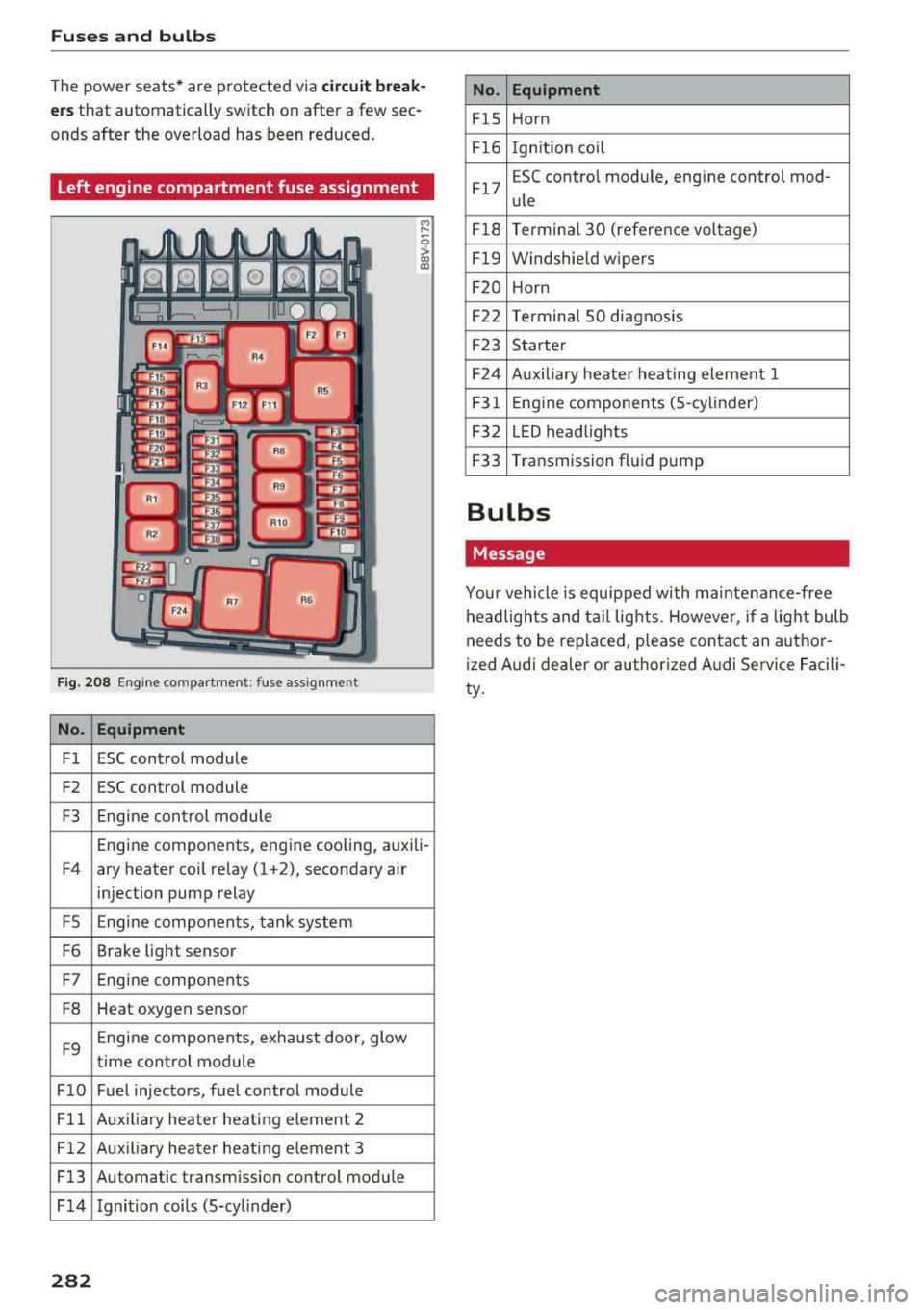
Left engine compartment fuse assignment
F ig. 208 Engine co mpartment : fuse assignment
No. Equipment
Fl ESC control module
F2 ESC control module
F3 Engine control module
M
" 0 > a, m
Engine components, engine cooling, auxili-
F4 ary heater coil relay (1 +2), secondary air
injection pump relay
FS Engine components, tank system
F6 Brake light sensor
F7 Engine components
F8 Heat oxygen sensor
F9 Engine components, exhaust door, glow
time control module
FlO Fuel injectors, fuel control module
Fll Auxiliary heater heating e lement 2
F 12 Aux iliary heater heat ing element 3
Fl3 Automatic transmission control module
F 14 Ignition coils (5-cylinder)
282
No. Equipment
FlS Horn
Fl6 Ignition coil
Fl7 E
SC contro l module, engine control mod-
ule
Fl8 Terminal
30 (reference voltage)
Fl9 Windshield wipers
F20 Horn
F22 Terminal SO diagnosis
F23 Starter
F24 Auxiliary heater heating element 1
F31 Engine
components (5 -cylinder)
F32 LED headlights
F33 Transmission fluid pump
Bulbs
Message
Your vehicle is equipped with ma intenance-free
headlights and tail lights. However, if a light bulb
needs to be replaced, please contact an author
ized Audi dealer or authorized Audi Service Facili
ty.
Page 285 of 310
Cl 00 .-< N r--N .-< 0 r--Vl 00
Emergency situations
General
This chapter is intended for trained emergency
crews and working personnel who have the nec
essary tools and equipment to perform these
operations.
Starting by pushing or
towing
~ Note
Vehicles with an automatic transmission can
not be started by pushing or towing.
Starting with jumper
cables
If necessary, the engine can be started by con
necting it to the battery of another vehicle .
If the engine should fail to start because of a dis
charged or weak battery, the battery can be con
nected to the battery of
another vehicle, using a
pair of jumper cables to start the engine.
Jumper cables
Use only jumper cables of sufficiently large cross
section
to carry the starter current safely. Refer
to the manufacturer's specifications.
Use only jumper cables with
insulated terminal
clamps which are distinctly marked :
plus(+) cable in most cases colored red
minus(-) cable
in most cases colored black.
A WARNING -
Batteries contain electricity, acid, and gas.
Any of these can cause very serious or fatal in
jury. Follow the instructions below for safe
handling of your vehicle's battery .
-Always shield your eyes and avoid leaning
over the battery whenever possible.
-A dead battery can freeze at temperatures
around 32 °F (0 °C) . If the vehicle battery is
frozen, you must thaw it before connecting
the jump start cables. If you do not, this in-
Emergency situations
creases the risk of an explosion and chemi
cal burns. After jump starting the vehicle,
drive to an authorized Audi dealer or author ized Audi Service Facility immediately to
have the vehicle battery checked.
- Do not allow battery acid to contact eyes or
skin . Flush any contacted area with water
immediately.
- Improper use of a booster battery to start a
vehicle may cause an explosion .
- Vehicle batteries generate explosive gases .
Keep sparks, flame and lighted cigarettes
away from batteries.
- Do not try to jump start any vehicle with a
low acid level in the battery .
- The voltage of the booster battery must also
have a 12-Volt rating . The capacity (Ah) of
the booster battery should not be lower
than that of the discharged battery. Use of
batteries of different voltage or substantial
ly different "Ah " rating may cause an explo
sion and personal injury.
- Never charge a frozen battery. Gas trapped
in the ice may cause an explosion.
- Never charge or use a battery that has been
frozen. The battery case may have be weak
ened.
- Use of batteries of different voltage or sub
stantially different capacity (Ah) rating may
cause an explosion and injury. The capacity
(Ah) of the booster battery should not be
lower than that of the discharged battery.
- Before you check anything in the engine
compartment, always read and heed all
WARNINGS
c>page 233.
@ Note
- Applying a higher voltage booster battery
will cause expensive damage to sensitive
electronic components, such as control
units, relays, radio, etc.
- There must be no electrical contact between
the vehicles as otherwise current could al
ready start to flow as soon as the positive
( + ) terminals are connected.
283
Page 286 of 310
Emergency situations
@ Tips
The discharged battery must be properly con·
nected to the vehicle's electrical system .
When jump starting or charging the battery,
never connect the negative ground cable to
the battery negative post because the battery
manager system must be able to detect the
battery's state of charge. Always connect the
negat ive g round cable to the negative ground
post of the battery manager control unit.
Using the jump start
cable
Both jump start cables must be connected in the
correct order!
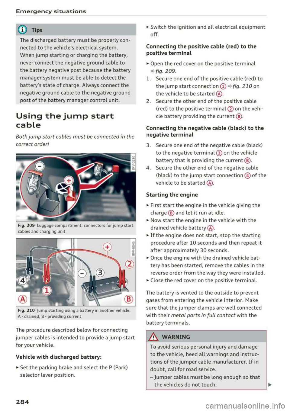
Fig. 209 luggage compartme nt: connectors for jump start
cables and charg ing unit
Fig. 210 Jump starting usi ng a battery in anot her vehicle:
A· drained, B • provid ing curren t
The procedure described below for connecting
jumper cables is intended to provide a jump start
for your vehicle.
Vehicle with discharged battery:
.. Set the parking brake and select the P (Park)
selector lever position.
284
.. Switch the ignition and all electrical equipment
off.
Connecting the positive cable (red) to the
positive terminal
.. Open the red cover on the positive terminal
<=:>fig. 209.
1. Secure one end of the positive cable (red) to
the ju mp start connection
(D c:> fig. 210 on
the vehicle to be started @.
2 . Secure the other end of the pos itive cable
(red) to the positive terminal @on the vehi·
cle battery prov iding the current @.
Connecting the negative cable (black ) to the
negative terminal
3 . Secure one end of the negative cable (black)
to the negative term inal @ on the vehicle
batte ry that is providing the current @.
4. Secure the other end of the negative cable
(black) to the jump start connection
@of the
vehicle to be started @.
Starting the engine
.,. First start the engine in the vehicle giving the
charge @ and let it run at idle .
.. Now start the engine in the vehicle with the
drained veh icle battery @.
.. If the engine does not start, stop the starting
procedure after 10 seconds and then repeat it
after approximately 30 seconds .
.. Once the engine with the drained vehicle bat·
tery has been started, remove the cables in the
reverse order from the way they were installed .
.. Close the red cover on the pos itive terminal.
The battery is vented to the outside to prevent
gases from enter ing the vehicle interior. Make
sure that the jumper clamps are well connected
with their
metal ports in full contact with the
battery termin als.
.&_ WARNING
To avoid serious personal injury and damage
to the vehicle, heed all warnings and instruc
tions of the jumper cable manufacturer. If in
doubt, call for road service .
- Jumper cables must be long enough so that
the vehicles do not touch.
Page 287 of 310
-When connecting jumper cables, make sure
that they cannot get ca ught in any mov ing
parts in the engine compartment.
- Do not bend over the batteries - danger of
chem ica l burns!
- The battery cell lock ing screws must be
t ightened sec ure ly.
- Be fore you check anything in the e ngine
compartment, a lways read and hee d all
WAR NINGS
q page 233 .
(D Note
Impro per hook -up of jum pe r cables can r uin
the gene rato r.
- Always connect POSITI VE (+ ) to POS ITIV E
( + ), and NEGATIVE( -) to NEGAT IVE( -)
g roun d post of t he battery mana ger contro l
u nit.
- Check that a ll sc rew p lugs on t he battery
cells are screwed in firmly. I f not, t ighten
plugs prior to connecting clamp on negative
batte ry terminal.
- Please note that the procedure fo r con nect
i ng a jumper cab le as desc ribed above ap
p lies specifica lly to the case of yo ur vehicle
being jump starte d. When you are giv ing a
ju mp s ta rt to anothe r vehicle, do
not con
n ect the neg ative (-) cab le to the neg ative
(-) t ermin al on the di sch arged b attery @
q fig. 210. In ste ad , securely connec t the
nega tive ( -) cab le to either a solid me tal
com ponent that is f irm ly bolted to the e n
gine block o r to the engine bloc k itself. If
the battery that is be ing cha rge d does not
vent to the outs ide, escap ing battery gas
could ignite and exp lode!
Towing with a tow truck
General hints
Your Audi requires special handling for towi ng .
The fo llow ing information is to be used by com
mercia l tow tr uck operators who know how to op-
a e rate the ir equip ment safe ly. co ....
~ - Never tow your Audi. Towing will cause dam-
"' 8 age to the engine and transmission . r--Vl co
Emergency situations
-Never wrap the safety chains or winch cables
around the brake lines .
- To prevent unnecessa ry damage , your Audi
must be transported with a flatbed truck.
- To load the vehicle on to the flatbed, use the
towing loop found in the vehicle tools and at
tach to the front or rear anchorage
¢ page 285 and ¢ page 286 .
A WARNING
-A veh icle being towed is not safe for passen-
ge rs. Neve r allow anyone to ride in a vehicle
b eing towed, fo r any r eason.
Front towing loop
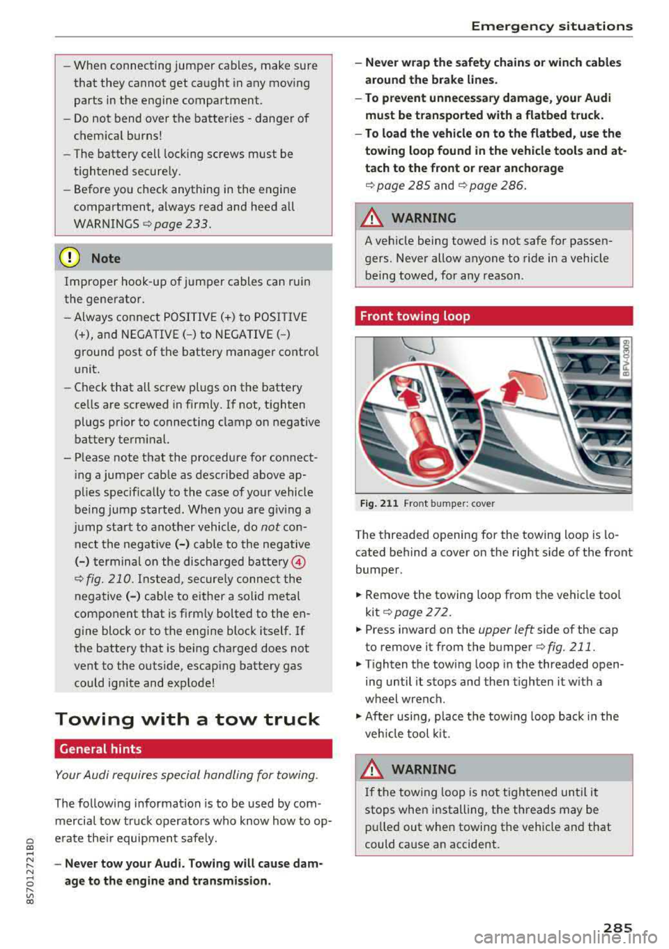
Fig. 2 11 Front bumper: cover
-
The threaded opening for the towing loop is lo
cated behind a cover on the right side of the front
bumper.
.,. Remove the towing loop from the vehicle too l
kit
¢ page 272.
.,. Press inward on the upper left side of the cap
to remove it from the bumper
¢fig. 211.
.,. Tighten the tow ing loop in the threaded open
ing until it sto ps and then tighten it w ith a
whe el wrench .
.,. After usi ng, p lace the tow ing loop b ack i n the
ve hicl e tool kit.
WARNING
If the towing loop is not ti ghtened until it
stops whe n installing, t he threads may be
pull ed out when towing the vehicle a nd that
could ca use an accident.
285
Page 288 of 310
Emergency situations
Rear towing loop
0
-M 0
ct Cl)
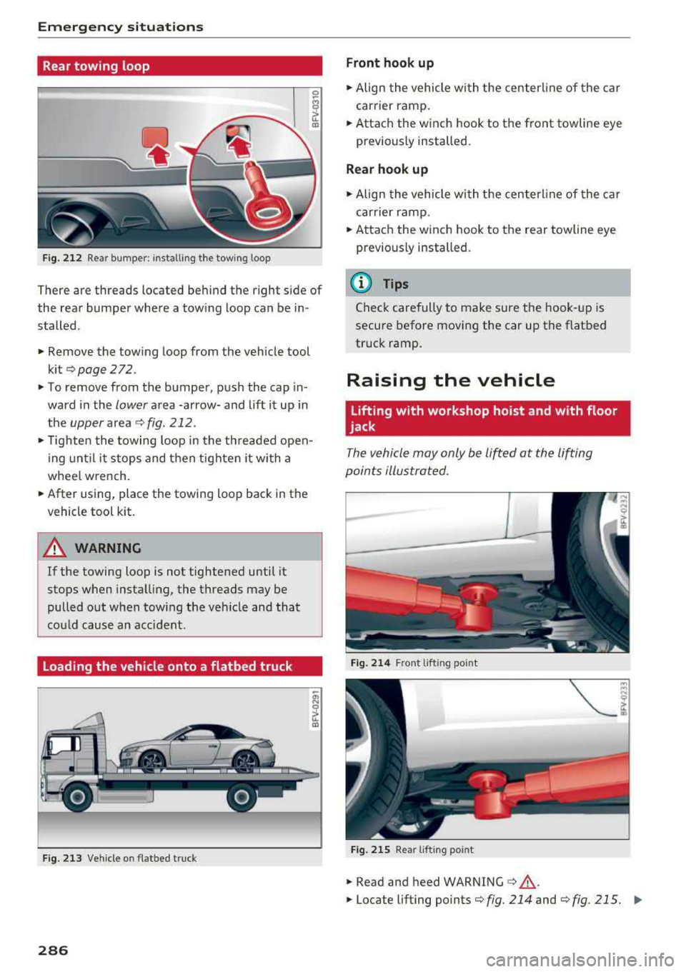
Fig. 212 Rear bumper: i nstalling the towing loop
There are threads located behind the right side of
the rear bumper where a towing loop can be in
stalled.
.. Remove the towing loop from the vehicle tool
kit
Q page 272.
.. To remove from the bumper, push the cap in
ward in the
lower area -arrow- and lift it up in
the
upper area ¢ fig. 212 .
.,. Tighten the towing loop in the threaded open
ing until it stops and then tighten it with a
whee l w rench .
.. After using, place the towing loop back in the
vehicle tool kit.
A WARNING
If the towing loop is not tightened until it
stops when installing, the threads may be
pulled out when tow ing the vehicle and that
cou ld cause an accident.
Loading the vehicle onto a flatbed truck
Fig. 213 Vehicle o n flatbed tru ck
286
Front hook up
.. Align the vehicle with the center line of the car
carrier ramp.
.. Attach the winch hook to the front towline eye
pr eviously installed.
Rear hook up
.,. Align the vehicle with the centerl ine of the car
carrier ramp .
.. Attach the winch hook to the rear towline eye
previously installed.
(D Tips
Check carefully to make sure the hook-up is
secure before moving the car up the flatbed
truck ramp .
Raising the vehicle
Lifting with workshop hoist and with floor
jack
The vehicle may only be lifted at the lifting
points illustrated .
Fig. 214 Front lifting point
Fig. 215 Rear lif ting po int
.,. Read and heed WARNING ¢&, .
.. Locate lifting points ¢fig. 214 and ¢fig . 215. II>
Page 289 of 310
Cl 00 .-< N r-N .-< 0 r-Vl 00
~ Adjust lifting a rms o f wo rkshop ho ist o r floo r
jack to match veh icle lifting points .
~ In se rt a r ubber pad between t he floor jack/
wor kshop hoist and the lifting points.
The vehicle jac k mode* must be activated so that
the automatic a djustment of the Adaptive Air
Suspension* does not make it more difficult to
raise t he ve hicle w it h the floor jac k.
If you must lift your vehicle with a floor jack to
work underneath , be sure the vehicle is safely
supported on stands intended for this purpose.
Front lifting point
T h e lif ting poi nt is locat ed on the floor pan re in
fo rceme nt abou t at t he s ame leve l as t he jac k
mo unt ing poin t
i::> fig . 214. Do not lift the vehi
cle at the vertical sill reinforcement.
Rear lifting point
T h e lif tin g point is loc ated o n the ve rt ical rein
f o rc eme nt of th e lowe r sil l fo r th e on-bo ard jac k
¢fig . 215.
Lifting with vehicle jack
Refer to i::> page 2 76 .
A WARNING
- T o re duc e th e risk of seri ous injur y an d vehi
cl e dama ge.
- A lways lift t he veh icle only at the s pecial
wo rksho p hoist and floo r jack lift po ints il
lust rated
¢ fig. 214 and ¢ fig. 215.
- Fa ilu re to li ft the vehicle at these points
could cause the vehicle t o til t or fa ll from
a li ft if there is a change in veh icle we ig ht
d istr ibu tion a nd balance. Th is m ight hap
p en , fo r e xamp le, wh en h eavy co m po
n e nts s uch a s the engi ne b lock or tran s
mission ar e re mo ved.
- W hen remo ving h eavy compo nents like
t h ese, anchor vehicle to hoi st or add cor re
s p ondi ng we ights to ma inta in t he ce nt er of
g ra vity . Ot herwise, the vehi cle m ight ti lt or
s lip off the hoist, causin g serio us persona l
injury .
Emergency situations
@ Note
-Be aware of t he fo llow ing poin ts befo re lift
in g th e vehicle:
-The vehicle should never be lifted or
jacked up from underneath the engine oil
pan, the transmission housing, the front
or rear axle or the body side members.
This could lead to serious damage.
- To avoid damage to the underbody or
chassis frame, a rubber pad must be in
serted between the floor jack and the lift
points.
- Before driving over a workshop hoist,
check that the vehicle weight does not
exceed the permissible lifting capacity of
the hoist.
- Before driving over a workshop hoist , en
sure that there is sufficient clearance be
tween the hoist and low parts of the ve
hicle.
287
Page 290 of 310
Technical data
Technical data
Vehicle specifications
XXXXX XX -X -X X XX XXX XX
©-+ = :::t::: XXXXXXXX XX X X X XX XX XX
IYP /rYP! XXX XXX
XX XXXXXXX XX X X XX
XXX
K W XXX
15\_J_ I lllfOlll(S ,/ liTR,kB. xxxx X XX XXX ~ Ut; . OOll / lllANS. 000!
©+ ~
1
:tf:l~
1
XXXX / XXXX XXX / XX
II. · AIJSliT. / OPTIONS
~--
EOA 7D 5 4U B 6XM 5S G 5R W
2 EH JO Z 1 LB 1AS 1BA
3FC
5 M U 7X 1
F O A 9G3 OG7 OY H OJF
TL 6 3KA 8EH U1A X 9B O Z7
lXW 803 908 8Z4 02D
7T6 C V7 7KO 4X3
2K2
3 L4 4KC 3Y O 413 50 2
1S A 7GB 0 1A 4G0
XX . X XX X XX X XXXX
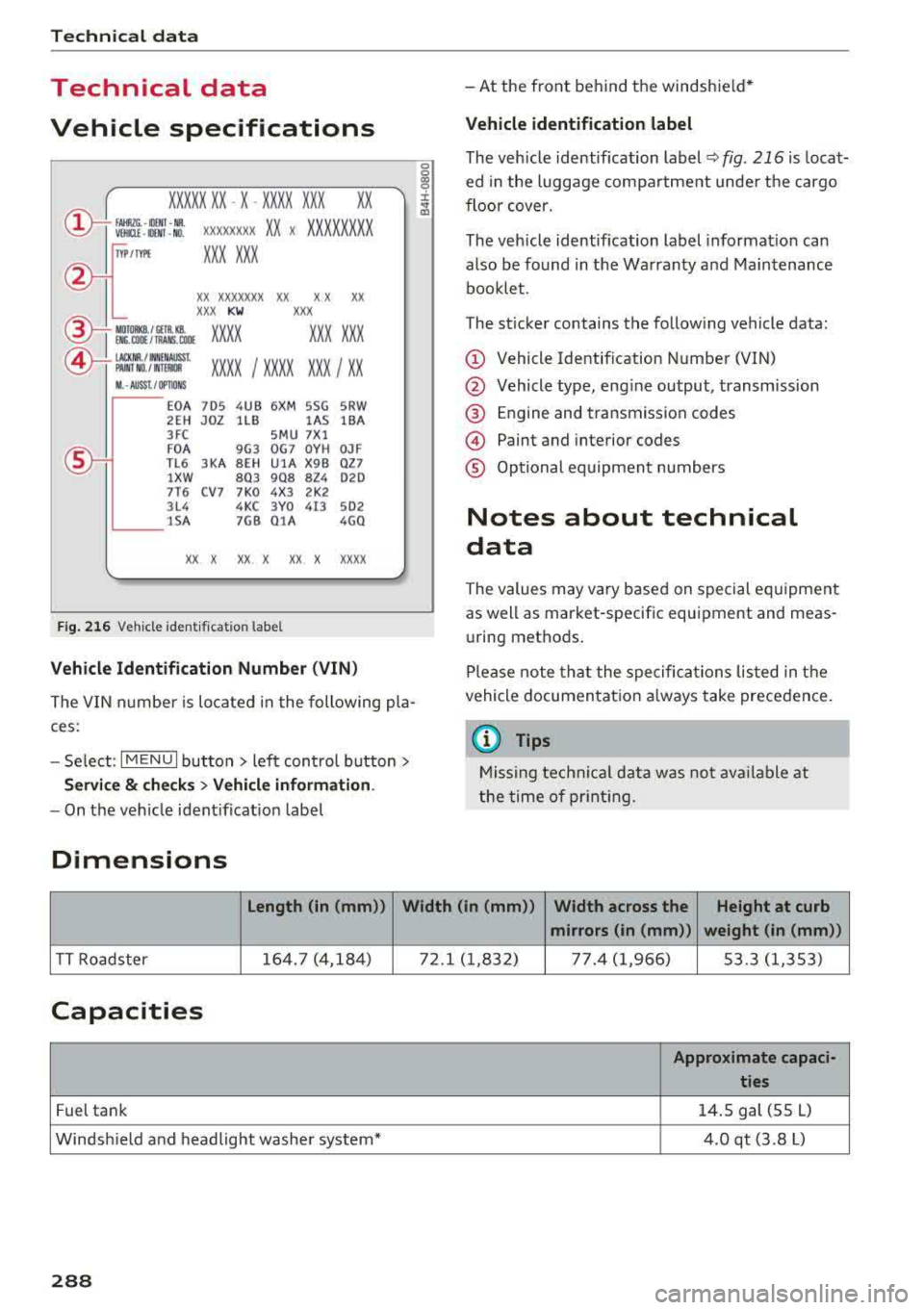
Fig. 21 6 Veh icl e ident ifi cation labe l
Vehicle Identification Number (VIN)
The VIN n umbe r is lo cated i n the following pla
ces :
-Select : I MENU I but to n > left con trol button>
Service & checks > Vehicle information .
-On the vehicle ident ificat io n label
Dimensions
0
0
~ :x: ... m
-At the front behind the windshie ld*
Vehicle identification label
The veh icle identification label Q fig . 216 is loca t·
ed in the luggage compartme nt unde r the cargo
floor cover.
The veh icle identification label informat ion can
also be found in t he Warranty and Maintenance
bookle t.
The st icker contains the follow ing vehicle data:
© Vehicle Identif ication Number (VIN)
@ Vehicle type, eng ine output, transmission
@ E ngine and transmission codes
© Paint and interior codes
® Op tional equipment numbers
Notes about technical
data
The values may vary based on special equipment
as well as market-specific equipment and meas u ring methods .
Please note that the spe cific ations liste d in the
vehicle documentat io n always take precedence .
a) Tips
Missing technical data w as not ava ilable at
the time of pr int ing.
length (in (mm )) Width (in (mm ))
Width across the Height at curb
mirrors (in (mm )) weight (in (mm))
TT Roadster 164. 7 (4,18
4) 72.1 ( 1,832) 77. 4 (1 ,966) 53.3 (1,353)
Capacities
Approximate capaci -
ties
Fuel tank 14
. 5 gal (55 L)
Windsh ield and headlight washe r system* 4.0 qt (3.8 L)
288