rear BMW 525i 1997 E39 Manual PDF
[x] Cancel search | Manufacturer: BMW, Model Year: 1997, Model line: 525i, Model: BMW 525i 1997 E39Pages: 1002
Page 448 of 1002
Downloaded from www.Manualslib.com manuals search engine
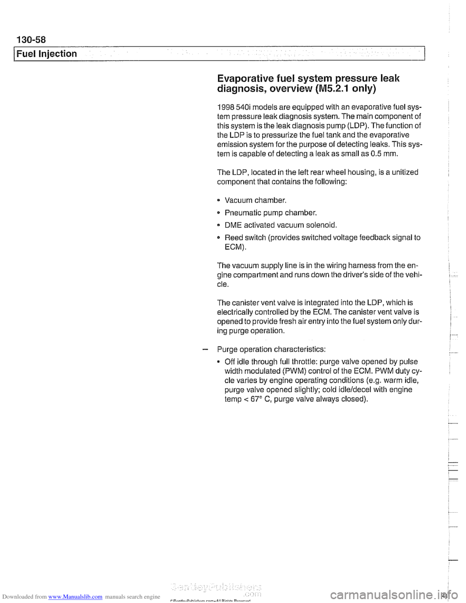
Fuel Injection Evaporative fuel system pressure leak
diagnosis, overview
(M5.2.1 only)
1998 540i models are equipped with an evaporative fuel sys-
tem pressure leak diagnosis system. The main component of
this system is the leak diagnosis pump (LDP). The function of
the LDP is to pressurize the fuel tank and the evaporative
emission system for the purpose of detecting
leaks. This sys-
tem is capable of detecting a leak as small as 0.5 mm.
The LDP, located in the left rear wheel housing, is a unitized
component that contains the following:
Vacuum chamber. Pneumatic pump chamber.
DME activated vacuum solenoid
Reed switch (provides switched voltage
feedback signal to
ECM).
The vacuum supply line is in the wiring harness from the en-
gine compartment and runs down the driver's side of the vehi-
cle.
The canister vent valve is integrated into the LDP, which is
electrically controlled by the ECM. The canister vent valve is
opened to provide fresh air entry into the fuel system only dur-
ing purge operation.
- Purge operation characteristics:
Off idle through full throttle: purge valve opened by pulse
width modulated (PWM) control of the ECM. PWM duty cy-
cle varies by engine operating conditions
(e.g. warm idle,
purge valve opened slightly; cold
idleldecel with engine
temp
< 67" C, purge valve always closed).
Page 451 of 1002
Downloaded from www.Manualslib.com manuals search engine
-. -
Fuel Injection
I 68 1 / Not used
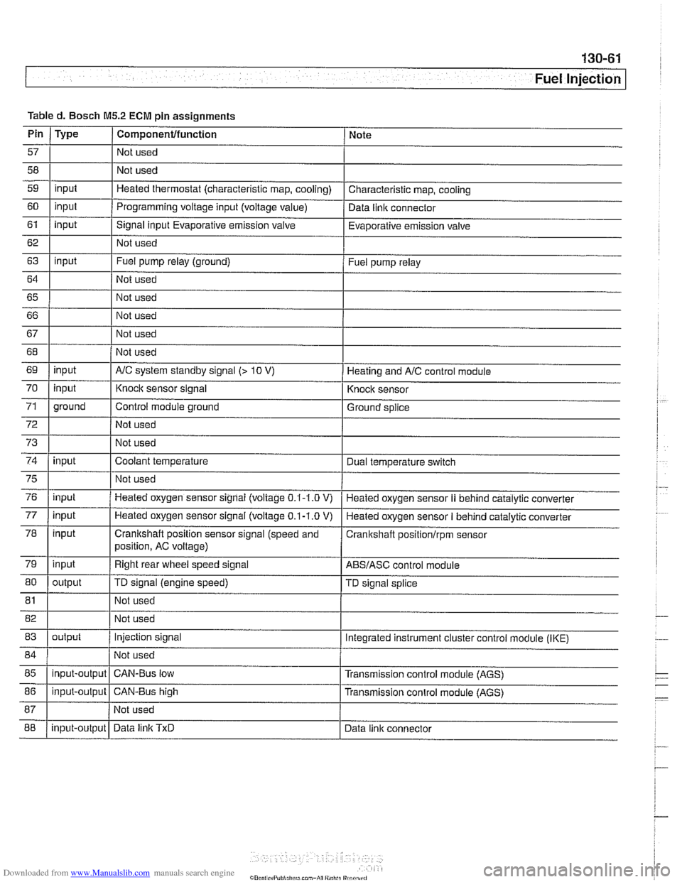
Table
d. Bosch
M5.2 ECM pin assignments
I I I
69 1 input I AIC system standby signal (> 10 V) 1 Heating and AIC control module
Pin
57
58
59
60
61
62
63
64
65 66
67
Type
input
input
input
input
I 70
72
73
74
Componentlfunction
Not used
Not used
Heated thermostat (characteristic map, cooling)
Programming voltage input (voltage
value)
Signal input Evaporative emission valve
Not used
Fuel pump relay (ground)
Not used
Not used
Not used
Not used
75
76
77
78
79
80
Note
Characteristic map, cooling
Data
llnlc connector
Evaporative emission valve
Fuel pump relay
71 1 ground I Control module ground I Ground splice
input
input
81
input input
input
input
output Not used
I
Knock sensor signal
Not used
Not used
Coolant temperature
82 1 I Not used
83
I I
Knock sensor
Dual temperature
swltch
Not used
Heated oxygen sensor signal (voltage
0.1-1.0 V)
Heated oxygen sensor
signal (voltage 0.1-1.0 V)
Crankshaft position sensor signal (speed and
position, AC voltage)
Right rear wheel speed signal
TD signal (engine speed)
85
I I I
Heated oxygen sensor II behind catalytic converter
Heated oxygen sensor
I behind catalytic converter
Cranitshaft positionlrpm sensor
ABSIASC control module
TD signal splice
84 1 / Not used 1
output
88
86
1 input-output 1 CAN-Bus high I Transmission conlrol module (AGS)
input-output
Injection signal
input-output Integrated instrument cluster control
module (IKE)
CAN-Bus low Transmission control module (AGS)
Data
linlc TxD Data link connector
Page 454 of 1002
Downloaded from www.Manualslib.com manuals search engine
-
Fuel Injection
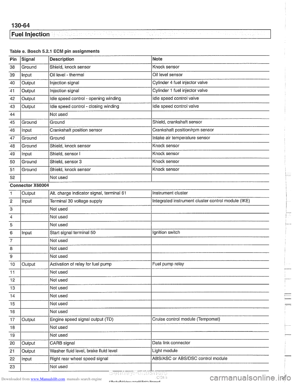
Table e. Bosch 5.2.1 ECM pin assignments
Pin
I~iqnal 1 Description 1 Note
I I I
46 llnput ICrankshaft position sensor Icrankshaft positionlrpm sensor
38
39
40
41
42
43
44
45 Ground Input
Output
Output
Output
Output
Ground
47
48
49
50
51
Not used
I Not used
52
Shield, knock sensor
Oil level
- thermal
Injection signal
injection signal
Idle speed control - opening winding
Idle speed control - closing winding
Not used
Ground
Ground
-- Ground Input
Ground
Ground Not used Knock sensor
Oil level sensor
Cylinder
4 fuel injector
valve
Cylinder
1 fuel injector valve
Idle speed control valve
Idle speed control valve
Shield, crankshaft sensor
5
6
7
12 Not used
Ground
Intake air temperature sensor
Connector
X60004
8
9 10
11
14 1 1 Not used I
Shield, knock sensor
Shield, sensor
I
Shield, sensor 3
Shield, itnock sensor
Input
- Knoclc sensor
Knock sensor
Knock sensor
Knock sensor
Instrument cluster
Output
2 llnput l~erminal 30 voltage supply /Megrated instrument cluster control module (IKE)
Alt. charge indicator signal, terminal 61 1
Not used
Start signal terminal
50
Not used
15
16
17
18
Output
Ignition switch
Not used
Not used
Activation of relay for fuel pump
Not used
19
Fuel pump relay
Output Not used
I I I 20 loutput ICARB signal /Data link connector
Not
used
Not used
Engine speed signal output (TD)
Not used
Light module
21
Cruise control module (Tempomat)
22 llnput I Right rear wheel speed signal /ABS/ASC or ABSIDSC control module
Oulput
Washer
fluid level,
brake fluid level
Page 456 of 1002
Downloaded from www.Manualslib.com manuals search engine
Fuel Injection
When system faults are detected, a diagnostic trouble code
(DTC) is stored in the engine control module (ECM). The MIL
also illuminates
if an emissions-related fault is detected.
When faults arise, or
if the malfunction indicator lamp (MIL) is
illuminated, begin troubleshooting by connecting BMW ser-
vice tester
DISplus, MoDiC, GTl or equivalent scan tool. The
capabilities of OBD
II software has the potential to save hours
of diagnostic time and to help avoid incorrect component re-
placement and possible damage to system components.
CA UTIOI\C
The tests in this section may set fault codes (DTCs) in the
ECM and illuminate the MIL. After all testing is completed,
access and clear DTC fault memory using an OBD
I1 or
BMW compatible scan tool. See OBD On-Board Diag-
nostics.
. Only use a digital multimeter for electrical tests.
Relay positions can vary. Be sure to confirm relay posi-
tion by identifying the wiring in the
socket using the wir-
ing diagrams found in ELE Electrical Wiring
Diaqrams.
NOTE-
= OBD I1 fault memory (including an illuminated MIL) can
only be reset using the special scan tool. Removing the
connector from the ECM or disconnecting the battery will
not erase the fault memory.
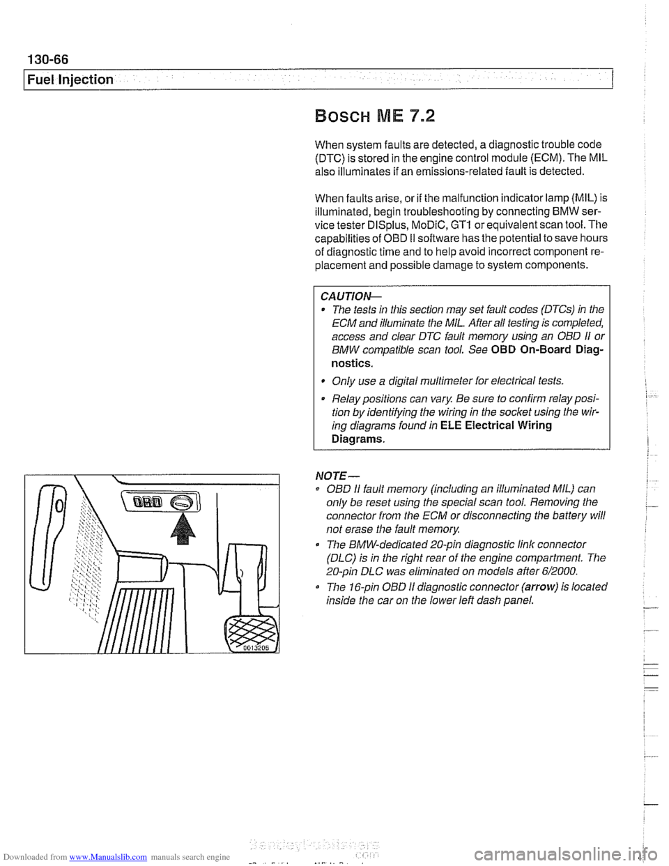
0 The BMW-dedicated 20-pin diagnostic link connector
(DLC) is in the right rear of the engine compartment. The
20-pin DLC was eliminated on models after
6/2000.
The 16-pin OBD I1 diagnostic connector (arrow) is located
inside the car on the lower left dash panel.
Page 460 of 1002
Downloaded from www.Manualslib.com manuals search engine
130-70
Fuel Injection
ECM relay
--
CAUTION-
Relay positions can vary Be sure to confirm relay position by
identifying the wiring in the
socl(et using the wiring diagrams
in ELE Electrical Wiring Diagrams.
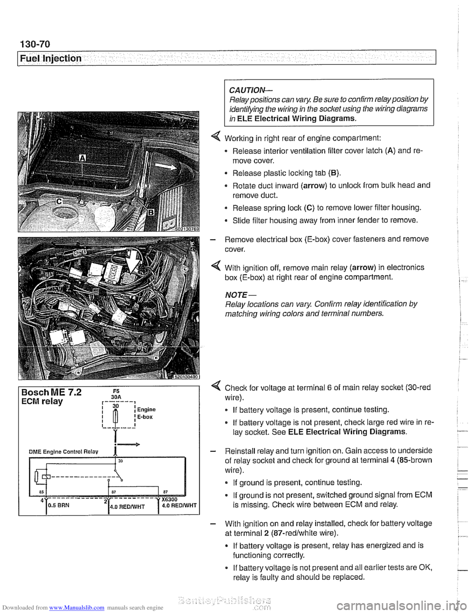
Working in right rear of engine compartment:
Release interior ventilation filter cover latch
(A) and re-
move cover.
Release plastic locking tab
(B).
Rotate duct inward (arrow) to unlock from bulk head and
remove duct.
Release spring
loclt (C) to remove lower filter housing.
Slide filter housing away from inner fender to remove.
- Remove electrical box (E-box) cover fasteners and remove
cover.
4 With ignition off, remove main relay (arrow) in electronics
box (E-box) at right rear of engine compartment.
NOTE-
Relay locations can vary Confirm relay identification by
matching wiring colors and terminal numbers.
4 Check for voltage at terminal 6 of main relay socket (30-red
wire).
If battery voltage is present, continue testing.
If battery voltage is not present, check large red wire in re-
lay socltet. See ELE Electrical Wiring Diagrams.
- Reinstall relay and turn ignition on. Gain access to underside
of relay socket and check for ground at terminal
4 (85-brown
wire).
If ground is present, continue testing.
If ground is not present, switched ground signal from ECM
is missing. Check wire between ECM and relay.
- With ignition on and relay installed, check for battery voltage
at terminal
2 (87-redlwhite wire).
If battery voltage is present, relay has energized and is
functioning correctly.
If battery voltage is not present and all earlier tests are OK.
relay is faulty and should be replaced.
Page 464 of 1002
Downloaded from www.Manualslib.com manuals search engine
130-74
I Fuel Injection
Evaporative system pressure leak
diagnosis, overview
The M62 TU engine is equipped wlth an evaporative fuel sys-
tem pressure leak diagnosis system. The main component of
this system is the leakdiagnosis pump (LDP). The function of
the LDP is to pressurize the fuel tank and the evaporative
emission system for the purpose of detecting leaks.
This system iscapable of detecting a
lealcas small as0.5 mm.
The LDP, located in the left rear wheel housing, contains the
following:
Vacuum chamber. Pneumatic pump chamber
DME activated vacuum solenoid
Reed switch (provides switched voltage
feedback signal to
DME).
The vacuum supply line is in the wiring harness from the en-
gine compartment and runs down the driver's side of the vehi-
cle.
The canister vent valve is
~ntegrated into the LDP, which IS
electrically controlled by the ECM. The canister vent valve is
opened to provide fresh air entry into the fuel system only dur-
ing purge operation.
- Purge operation characteristics:
Off idle through full throttle: purge valve opened by pulse
width modulated (PWM) control of the ECM. PWM duty cy-
cle varies by engine operating conditions
(e.g. warm idle,
purge valve opened slightly; cold
idleldecel with engine
temp
< 67" C. purge valve always closed).
Page 469 of 1002
Downloaded from www.Manualslib.com manuals search engine
Fuel Injection I
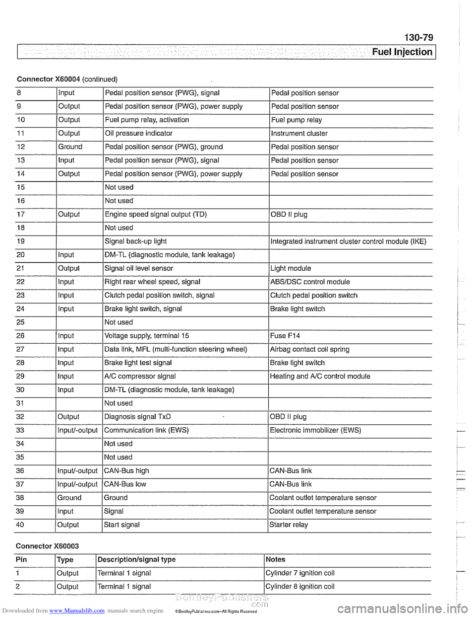
Connector X60004 (continued)
8 10
11
12
13
14
15
16
9
Output 0
Input
17
18
19
20
21
22
23
24
25
26
27
28
29
30
31
32
33
34
35
36
39
llnput lsignal l~oolant outlet temperature sensor
Output
Output
Ground
Input
Output
I I - I
40 /output Istart signal Istarter relay
Pedal position sensor (PWG), signal
Output Input
Output
input
Input
Input
Input
Input
Input
input
Input
Output
Input/-output
Input/-output
37
Connector X60003
Pedal position sensor
Fuel pump relay, activation
Oil pressure indicator Pedal position sensor (PWG), ground
Pedal position sensor (PWG), signal
Pedal position sensor (PWG), power supply
Not used
Not used Fuel
pump relay
Instrument cluster
Pedal position sensor
Pedal position sensor
Pedal position sensor
Engine speed signal output (TD)
Not used
Signal
back-up light
DM-TL (diagnostic module,
tank leakage)
Signal oil level sensor
Right rear wheel speed, signal
Clutch pedal position switch, signal
Brake light switch, signal
Not used
Voltage supply, terminal
15
Data link, MFL (multi-function steering wheel)
Brake light test signal
AJC compressor signal
DM-TL (diagnostic module, tank
leakage)
Not used
Diagnosis signal
TxD
Communication link (EWS)
Not used
Not used
CAN-BUS hiqh
38 1 Ground l~round I Coolant outlet temperature sensor
OED II plug
Integrated instrument cluster control module (IKE)
Light module
ABSIDSC control module
Clutch pedal position switch
Brake light switch
Fuse
F14
Airbag contact coil spring
Brake light switch
Heating and
A/C control module
OBD
II plug
Electronic immobilizer (EWS)
CAN-Bus link
CAN-Bus link
Input/-output CAN-Bus low
Page 477 of 1002
![BMW 525i 1997 E39 Manual PDF Downloaded from www.Manualslib.com manuals search engine
- Fuel Tank and Fuel pump]
Remove fuel pump
relay (arrow).
4 Connect relay socitet terminal 6 (redlviolet wire) to relay
socket termi](/img/1/2822/w960_2822-476.png "BMW 525i 1997 E39 Manual PDF Downloaded from www.Manualslib.com manuals search engine
- Fuel Tank and Fuel pump]
Remove fuel pump
relay (arrow).
4 Connect relay socitet terminal 6 (redlviolet wire) to relay
socket termi")
Downloaded from www.Manualslib.com manuals search engine
- Fuel Tank and Fuel pump]
Remove fuel pump
relay (arrow).
4 Connect relay socitet terminal 6 (redlviolet wire) to relay
socket terminal
2 (whitelblue wire) with a fused jumper wire.
After completing tests, remove jumper harness.
CA
UTIOG
Relay locations may vary Use care when identifying relays
and making electrical checks at
the fuse/relay panel. See
610 Electrical Component Locations for additional re-
lay information.
The fuel pump relay has a 1.5
md red/violet wire at
terminal
6 in the relay socket. Terminal2 has a 2.5md
white/blue wire. See ELE Electrical Wiring Diagrams
for additional wiring information.
NOTE-
* The fuel pump will run as soon as the jumper wire Is at-
tached.
The jumper wire should be 1.5
md (14 ga.) and include
an in-line fuse holder with a 15A fuse. To avoid
fuse/relay
panel damage from repeated connecting and disconnect-
ing, also include a toggle switch in the jumper harness.
- If pump does not run with jumper installed, fault could be in
fuel pump, fuses
F31 or F22 1 F54, or wiring to pump. Check
pump, fuses and its wiring as described below.
Fuel pump electrical circuit, testing
- The test given below assumes that the fuel pump relay circuit
is functioning correctly as described earlier. Access to the
pump is from below the rear seat bottom cushion.
- Remove rear seat lower cushion by lifting front edge off left
and right catches.
Page 485 of 1002
Downloaded from www.Manualslib.com manuals search engine
.-
err- .- Fuel Tank and Fuel Pump
FUELPUMP AND FUELLEVELSENDER
E39 models use a two-lobed fuel tank. Each lobe of the tank
has its own fuel level sending unit. Each sender has a float
connected to a variable resistance wipercontact. To equalize
fuel level between the two
tank lobes, a siphon pump is in-
stalled in the left lobe.
When replacing asender or fuel pump, always replace hose
clamps,
gasltets and O-rings.
WARNING
-
When removing the fuel level sender or the fuel pump, the
fuel tank should be drained to
1/4 capacity or below as de-
scribed later in this repair group.
NOTE-
The compensating siphon pump maintains the fuel level be-
tween the right and left tank lobes. If fuel level sender resis-
tances are not approximately the same on left and right,
remove the senders and visually inspect the level in each
lobe. If the levels are different, check the siphon pump.
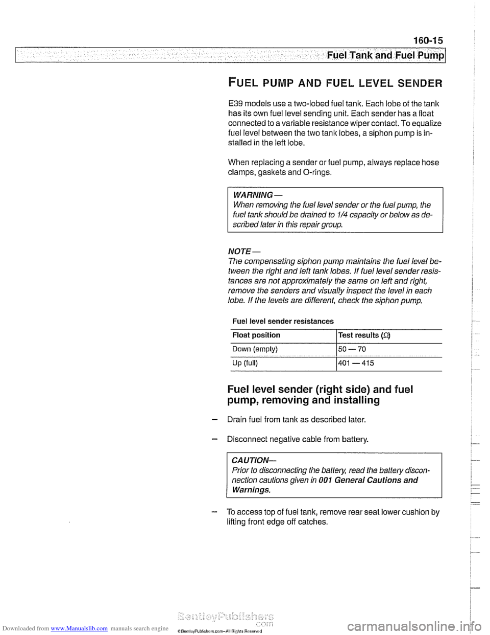
Fuel level sender resistances
Float position
l~est results (Q
Down (empty) 150- 70
Up (full) 1401 -415
Fuel level sender (right side) and fuel
pump, removing
and installing
- Drain fuel from tank as described later.
- Disconnect negative cable from battery.
CAUTION-
Prior to disconnecting the battery, read the battery discon-
nection cautions given in
001 General Cautions and
Warnings.
- To access top of fuel tank, remove rear seat lower cushion by
lifting front edge
off catches.
Page 487 of 1002
Downloaded from www.Manualslib.com manuals search engine
.- .
Fuel Tank and Fuel Pump
- To reinstall:
Use new sealing ring at tank collar.
* Align tab of sending unit with matching recess in opening
of tank.
Be sure that fuel line connections point in same direction
as they came out.
Reconnect harness connector and hose.
Fill tank and check for leaks by running engine.
Install access cover and its mounting fasteners.
CAUTIOI\C
After finishing repairs but before starting engine, be sure
there is at least
5 liters (1.5 gallons) of fuel in the tank. The
NOTE-
It is common practice to replace the fuel filter when the fuel
pump
unit is replaced. See 020 Maintenance.
Tightening torque
Tank collar locking ring to tank 35 Nm (26 lb-ft)
Fuel level sender (left side),
removing and installing
The procedure for removing and replacing the left side fuel
level sender is
simllar to that used for the r~ght side. There is
no fuel pump on the left side.
- Remove rear seat lower cushion by lifting off catches at front.
- Expose left side access cover:
- Peel forward lip of carpet.
Release rubber grommet from center of access cover
insulation.
Peel back insulation at
perforations to expose fuel tank
access cover.
Remove cover to expose electrical harness connector.
WARNING-
Fuel may be spilled. Do not smoke or work near heaters or
other fire hazards.
When disconnecting fuel hose, wrap shop rag around
end of hose to prevent spray of fuel under pressure.