rear BMW 525i 1997 E39 Manual Online
[x] Cancel search | Manufacturer: BMW, Model Year: 1997, Model line: 525i, Model: BMW 525i 1997 E39Pages: 1002
Page 490 of 1002
Downloaded from www.Manualslib.com manuals search engine
--
I Fuel Tank and Fuel Pump
The plastic fuel tank is mounted underneath the center of the
car (underneath the rear seat). Mounted in the fuel tank are
the fuel pump and fuel level sending units. Connecting lines
for the evaporative emission control system and expansion
tank are also attached to the tank.
Fuel
tank capacity for E39 models
Tank capacity
70 liters (18.5 gal)
Reserve capacity
8 liters (2.1 gal)
Fuel tank, draining
Drain fuel tank into a safe storage unit using an approved fuel
pumping device.
WARNING-
# Before removing tank, be sure that all hot components,
such as the exhaust system, are completely cooled down.
Fuel may be spilled. Do not smoke or
work near heat-
ers or other fire hazards.
- Start engine and allow to run 10 - 15 seconds to fill fuel com-
pensating siphon assembly. This will allow both lobes of fuel
tank to he drawn off through fuel filler pipe,
- Disconnect negative cable from battery.
CAUTION-
Prior to disconnecting the batteg read the battery discon-
nection cautions given
in 001 General Warnings and Cau-
tions.
- Remove fuel tank filler cap
- Slide suction hose into filler neck about 130 cm (51 in.), twist-
ing as necessary. Withdraw fuel into storage unit.
- Monitor fuel level reduction in both lobes:
- Remove rear seat cushion and access both fuel tank send-
er harness connectors.
Use multimeter to measure resistance at both senders,
Resistance should drop as fuel level drops.
- If siphoning mechanism is faulty, drain left tank lobe sepa-
rately by removing sender cover and pumping fuel directly
out of left lobe.
Page 491 of 1002
Downloaded from www.Manualslib.com manuals search engine
Fuel Tank and Fuel pump/
- Remove suction hose from tank filler neck carefully to avoid
damaging filler neck baffle plate.
CAUTION-
After finishing repairs but before starling engine, be sure
there is at least
5 liters (1.5 gallons) of fuel in tanlc. The fuel
pump will be damaged if run without fuel.
Fuel tank, removing and installing
- Remove fuel tank filler cap and drain tank as described
earlier.
- Disconnect negative cable from battery.
CAUTION-
Prior to disconnecting the battea read the battery discon-
nection cautions given in
001 General Cautions and
Warnings.
- Remove rear seat bottom cushion. Peel forward lip of carpet
from beneath seat cushion and carefully peel back insulation
to expose fuel tank access cover on left and right sides. Re-
move covers.
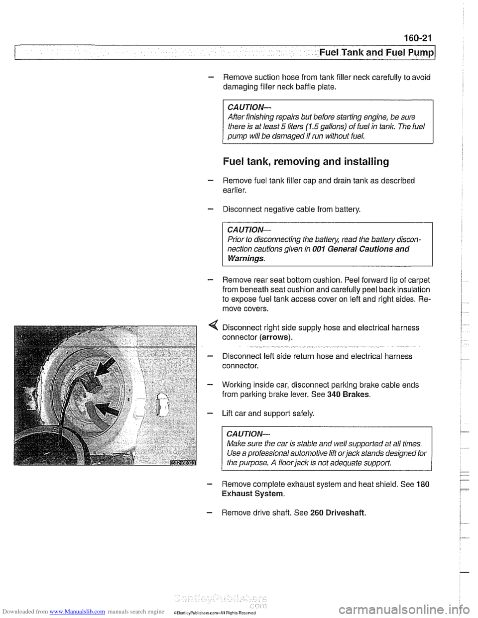
Disconnect right side supply hose and
electr~cal harness
connector (arrows).
D~sconnect left side return hose and electrical harness
connector.
Working inside car, disconnect parking
bralte cable ends
from parking brake lever. See
340 Brakes.
Lift car and support safely.
Make sure the car is stable and
we/ supported at all times.
Use a professional automotive lift
orjack stands designed for
the purpose. A floorjaclc is not adequate support.
- Remove complete exhaust system and heat shield. See 180
Exhaust System.
- Remove drive shaft. See 260 Driveshaft
Page 492 of 1002
Downloaded from www.Manualslib.com manuals search engine
160-22
Fuel Tank and Fuel Pump
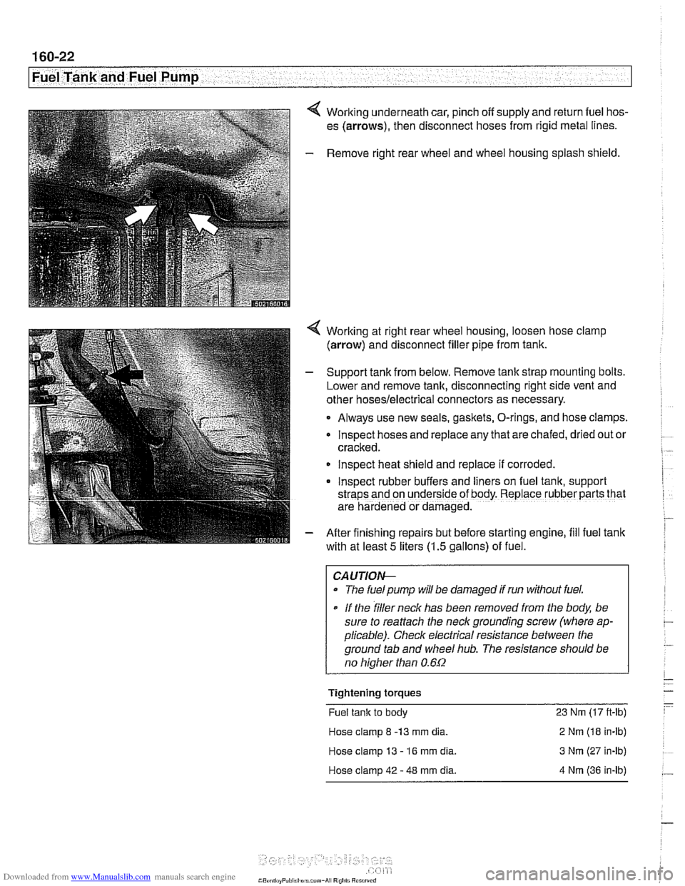
4 Working underneath car, pinch off supply and return fuel hos-
es (arrows), then disconnect hoses from rigid metal lines.
- Remove right rear wheel and wheel housing splash shield.
4 Worlting at right rear wheel housing, loosen hose clamp
(arrow) and disconnect filler pipe from tank.
- Support tank from below. Remove tank strap mounting bolts.
Lower and remove tank, disconnecting right side vent and
other
hoses/electrical connectors as necessary.
Always use new seals, gaskets, O-rings, and hose clamps.
lnspect hoses and replace any that are chafed,
dr~ed out or
cracked.
lnspect heat shield and replace if corroded.
Inspect rubber buffers and
hers on fuel tank, support
straps and on underside of body. Replace rubber parts that
are hardened or damaged.
- After finishing repairs but before starting engine, fill fuel tank
with at least
5 liters (1.5 gallons) of fuel.
CAUTlOI+
The fuelpump will be damaged if run without fuel.
* If the filler neck has been removed from the body, be
sure to reattach the
neck grounding screw (where ap-
plicable). Check electrical resistance between the
ground tab and wheel
hub. The resistance should be
no
hiaher than 0.6f2
Tightening torques
Fuel tank to body 23 Nm (17 ft-lb)
Hose clamp
8 -13 mm dia. 2 Nm (18 in-lb)
Hose clamp 13
- 16 mm dia. 3 Nm (27 in-lb)
Hose clamp 42
- 48 mm dia. 4 Nm (36 in-lb)
Page 493 of 1002
Downloaded from www.Manualslib.com manuals search engine
.- Fuel Tank and Fuel pump( -
Fuel expansion tank, removing
and installing
- Raise rear end of car and support safely.
CA U TIOG
Make sure the car is stable and well supported at all times.
Use a professional automotive lift
orjack stands designed for
the
ouroose. A floor iack is not adequate support
- Remove left rear wheel and wheel housing inner shield.
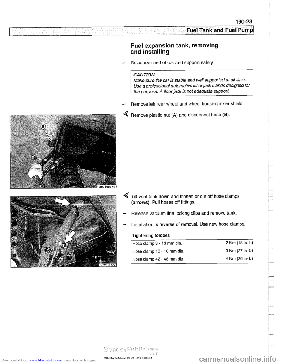
4 Remove plastic nut (A) and disconnect hose (B).
4 Tilt vent tank down and loosen or cut off hose clamps
(arrows). Pull hoses off fittings.
- Release vacuum line loclting clips and remove tank
- Installation is reverse of removal. Use new hose clamps.
Tightening torques
Hose clamp 8 - 13 mm dia. 2 Nrn (18 in-lb)
Hose clamp 13 - 16 mm dia. 3 Nm (27 in-lb)
Hose clamp
42 - 48 mm dia. 4 Nm (36 in-lb)
Page 494 of 1002
Downloaded from www.Manualslib.com manuals search engine
Fuel Tank and Fuel Pump 1
Activated carbon canister I fuel tank leak
detection unit
(LDP or DMTL), removing . . -
and installing
- Raise rear end of car and support safely.
CAUTION-
Make sure the car is stable and well supported at all times.
Use a professional automotive lift
orjack stands designed for
the purpose.
A floor jack is not adequate support.
- Remove left rear wheel and inner fender panel
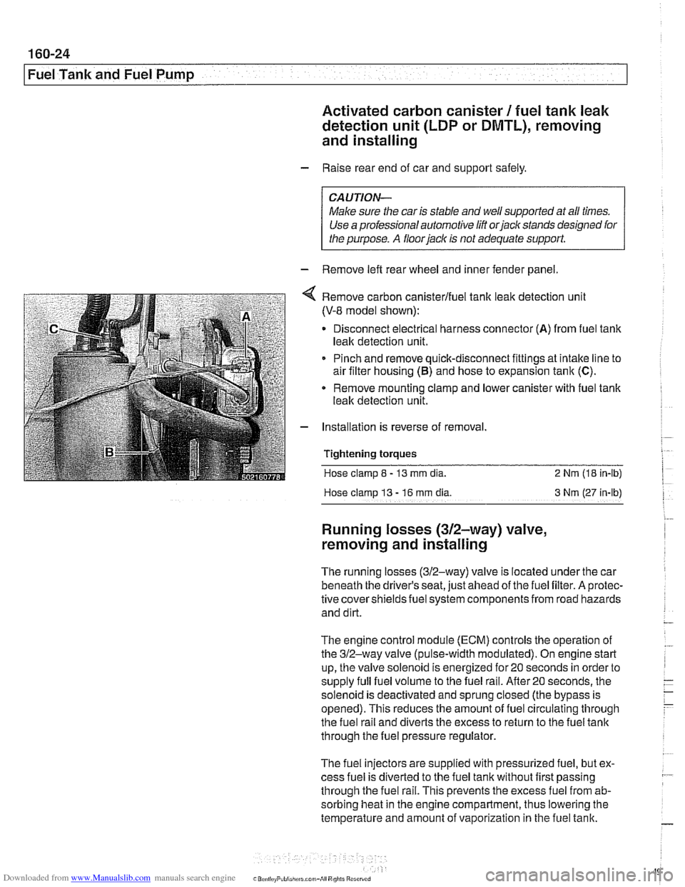
Remove carbon canisterlfuel tank leak detection unit
(V-8 model shown):
Disconnect electrical harness connector
(A) from fuel tank
leak detection unit.
Pinch and remove quick-disconnect fittings at intake line to
air filter housing
(5) and hose to expansion tank (C).
* Remove mounting clamp and lower canister with fuel tank
leak detection unit.
Installation is reverse of removal.
Tightening
torques
Hose clamp 8 - 13 mm dia. 2 Nrn (18 in-lb)
Hose clamp
13 - 16 rnm dia 3 Nm (27 in-lb)
Running losses (312-way) valve,
removing and installing
The running losses (312-way) valve is located under the car
beneath the driver's seat, just ahead of the fuel filter. A protec-
tive covershieldsfuel system components from road hazards
and dirt.
The engine control module
(ECM) controls the operation of
the 312-way valve (pulse-width modulated). On engine start
up, the valve solenoid is energized for 20 seconds in order to
supply full fuel volume to the fuel rail.
After20 seconds, the
solenoid is deactivated and sprung closed (the bypass is
opened). This reduces the amount of fuel circulating through
the fuel rail and diverts the excess to return to the fuel tank
through the fuel pressure regulator.
The fuel injectors are supplied with pressurized fuel, but ex-
cess fuel is diverted to the fuel tank without first passing
through the fuel rail. This prevents the excess fuel from ab-
sorbing heat in the engine compartment, thus lowering the
temperature and amount of vaporization in the fuel tank.
Page 517 of 1002
Downloaded from www.Manualslib.com manuals search engine
Radiator and Coolina ~vsteml
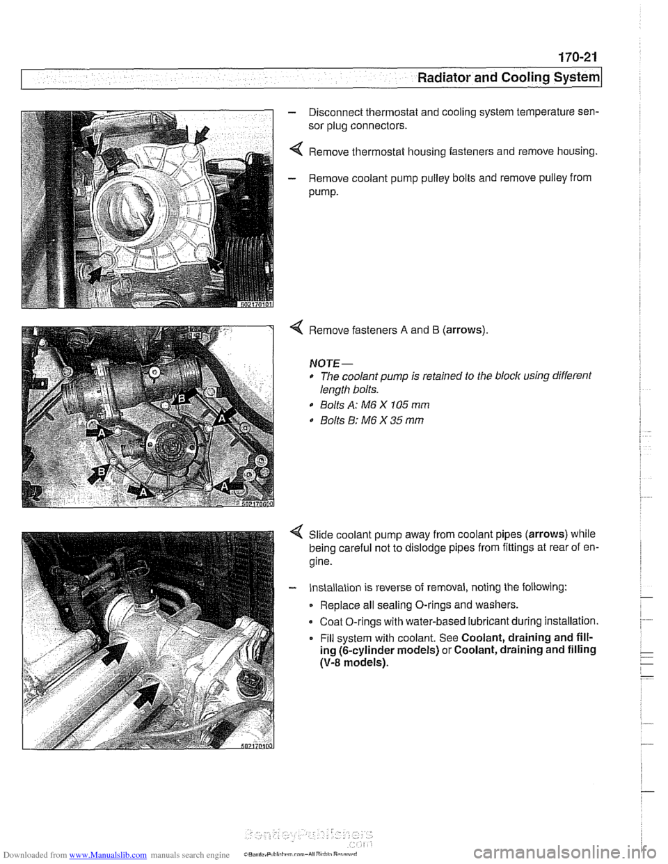
- Disconnect thermostat and cooling system temperature sen-
sor plug connectors.
4 Remove thermostat housing fasteners and remove housing.
- Remove coolant pump pulley bolts and remove pulley from
pump.
Remove fasteners A and B (arrows).
NOTE-
* The coolant pump is retained to the block using different
length bolts.
0 Bolts A: M6 X 105 mm
0 Bolts 8: M6 X 35 mm
Slide coolant pump away from coolant pipes (arrows) while
being careful not to dislodge pipes from fittings at rear of en-
gine.
- Installation is reverse of removal, noting the following:
Replace all sealing O-rings and washers.
Coat O-rings with water-based lubricant during installation.
Fill system with coolant. See Coolant, draining and fill-
ing (6-cylinder models) or Coolant, draining and filling
(V-8 models).
Page 525 of 1002
Downloaded from www.Manualslib.com manuals search engine
... .
Exhaust System
- With exhaust system fully cold, raise and support car for ac-
cess to exhaust system.
WARNING -
Do not worlc under a lifted car unless it is solidly supported on
jack stands designed for that purpose. Never work under a
car that is supported solely by a
jack.
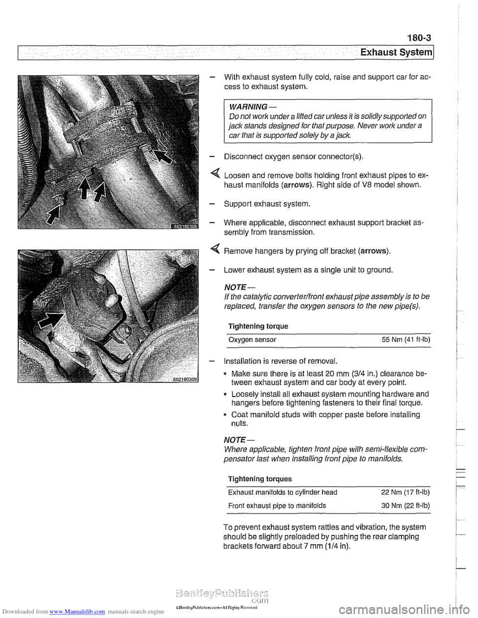
- Disconnect oxygen sensor connector(s).
4 Loosen and remove bolts holding front exhaust pipes to ex-
haust manifolds (arrows). Right side of
V8 model shown.
- Support exhaust system
- Where applicable, disconnect exhaust support bracket as-
sembly from transmission.
< Remove hangers by prying off bracket (arrows).
- Lower exhaust system as a single unit to ground.
NOTE-
If the catalytic converterlfront exhaust pipe assembly is to be
replaced, transfer the oxygen sensors to the new
pipe(s).
Tightening torque
Oxygen sensor
55 Nm (41 ft-lb)
- installation is reverse of removal.
* Make sure there is at least 20 mm (314 in.) clearance be-
tween exhaust system and car body at every point.
Loosely install
ail exhaust system mounting hardware and
hangers before tightening fasteners to their final torque.
Coat manifold studs with copper paste before installing
nuts.
NOTE-
Where applicable, tighten front pipe with semi-flexible com-
pensator last when installing front pipe to
manifolds.
Tightening torques
Exhaust manifolds
to cylinder head 22 Nm (1 7 It-lb)
Front exhaust pipe to manifolds 30 Nm (22 ft-lb)
To prevent exhaust system rattles and vibration, the system
should be slightly preloaded by pushing the rear clamping
brackets forward about 7 mm (114 in).
Page 526 of 1002
Downloaded from www.Manualslib.com manuals search engine
/Exhaust System Muffler, replacing
BMW offers individual mufflers as replacement parts for the
original one-piece assembly. Replacement of a rear muffler
may be possible with the system installed on the car. Re-
placement of the front or middle muffler should only be done
with the exhaust removed from the car.
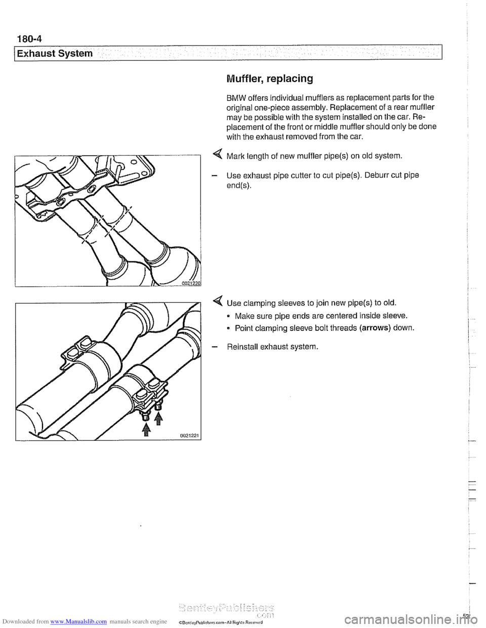
< Mark length of new muffler pipe(s) on old system.
- Use exhaust pipe cutter to cut pipe(s). Deburr cut pipe
end@).
4 Use clamping sleeves to join new pipe(s) to old.
Make sure pipe ends are centered inside sleeve.
Point clamping sleeve bolt threads
(arrows) down.
- Reinstall exhaust system.
Page 528 of 1002
Downloaded from www.Manualslib.com manuals search engine
180-6
Exhaust System
Exhaust manifolds, removing and installing
(M52 TU and M54 engines)
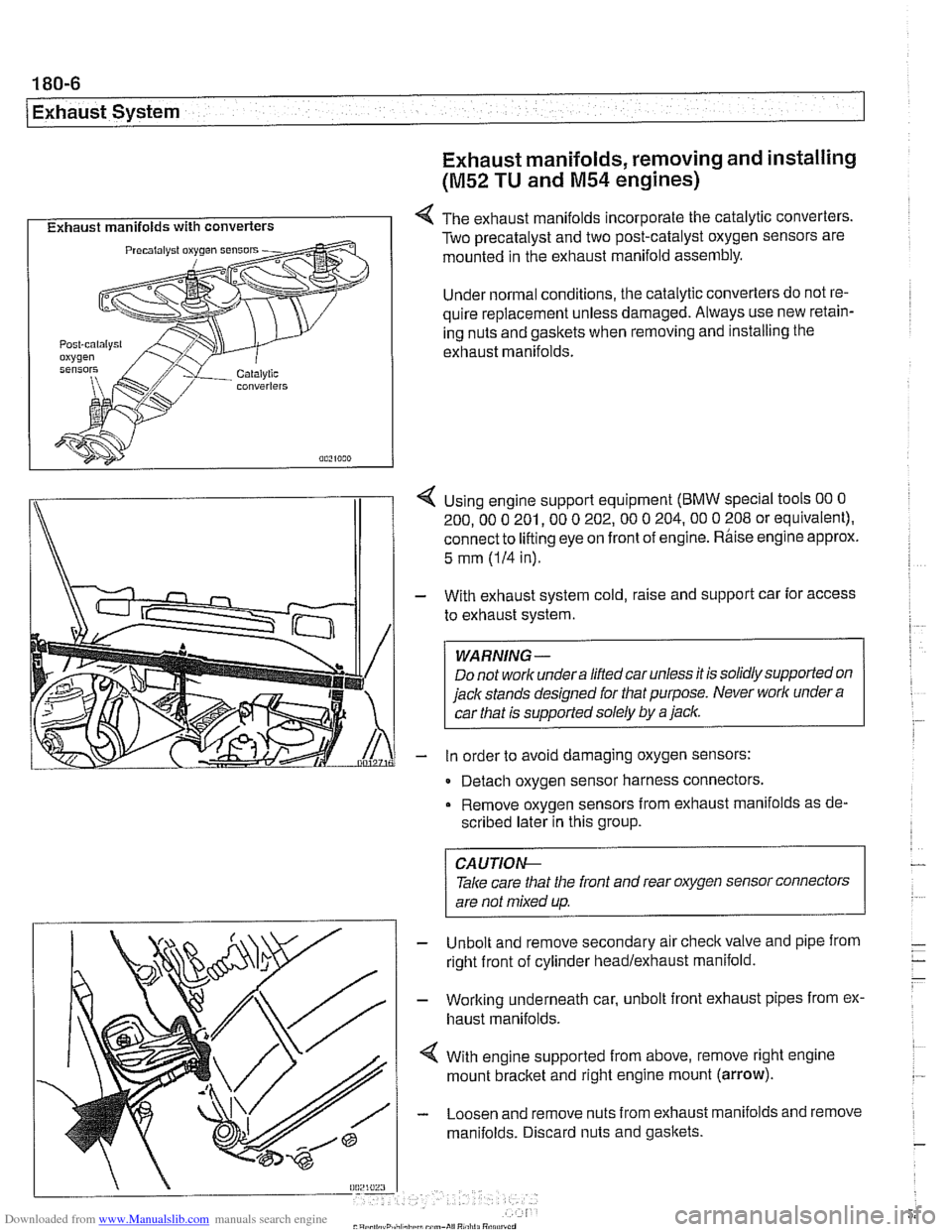
I Exhaust manifolds with converters I 4 The exhaust manifolds incorporate the catalytic converters.
Two precatalyst and two post-catalyst oxygen sensors are
mounted in the exhaust manifold assembly.
Under normal conditions, the catalytic converters do not re-
quire replacement unless damaged. Always use new retain-
ing nuts and gaskets when removing and installing the
exhaust manifolds.
I\
1 4 Using engine support equipment (BMW special tools 00 0
200. 00 0 201. 00 0 202.00 0 204.00 0 208 or equivalent).
connect to
lifting eye on front of engine. Rhise engine approx.
/I 1
5 mm (IH in).
With exhaust system cold, raise and support car for access
to exhaust system.
WARNING-
Do not worlc undera liftedcar unless it is solidly supported on
jack stands designed for that purpose. Never worlc under
a
car that is supported solely by a jaclc.
in order to avoid damaging oxygen sensors:
- Detach oxygen sensor harness connectors,
Remove oxygen sensors from exhaust manifolds as de-
scribed later in this group.
Unbolt and remove secondary air
checkvalve and pipe from
right front of cylinder headlexhaust manifold.
Working underneath car, unbolt front exhaust pipes from ex.
haust manifolds.
With engine supported from above, remove right engine
mount
bracket and right engine mount (arrow).
Loosen and remove nuts from exhaust manifolds and remove
manifolds. Discard nuts and gaskets.
CA UTIOG
Take care tliat the front and rear oxygen sensor connectors
are not mixed up.
-
Page 529 of 1002
Downloaded from www.Manualslib.com manuals search engine
1 Exhaust ~vsteml
NOTE-
The front exhaust manifold must be removed before the rear
manifold.
- Installation is reverse of removal.
Coat exhaust mounting studs with CRC or equivalent cop-
per paste.
Use new gasltets and self-locking nuts.
Tightening torques Exhaust manifold to cylinder head 20 Nm
(15 ft-lb)
Front exhaust pipe to manifold 30 Nm
(22 ft-lb)
Oxygen sensor to manifold 50
Nrn (37 ft-lb)
Exhaust manifolds, removing and installing
(M62 engine)
Always use new retaining nuts and gasltets when removing
and installing the exhaust manifolds.
NOTE-
Access to manifolds is extremely limited. If removing exhaust
manifolds as part of additional engine worlc (such as cylinder
head removal), it may be easier to first remove engine.
- With exhaust system cold, raise and support car for access
to exhaust system.
WARNING -
Do not work undera lifted car unless it is solidly supported on
jaclt stands designed for the purpose. Never worlc undera car
that is supportedsolely
by a jack.
- Remove exhaust system. See Exhaust system, removing
and installing.
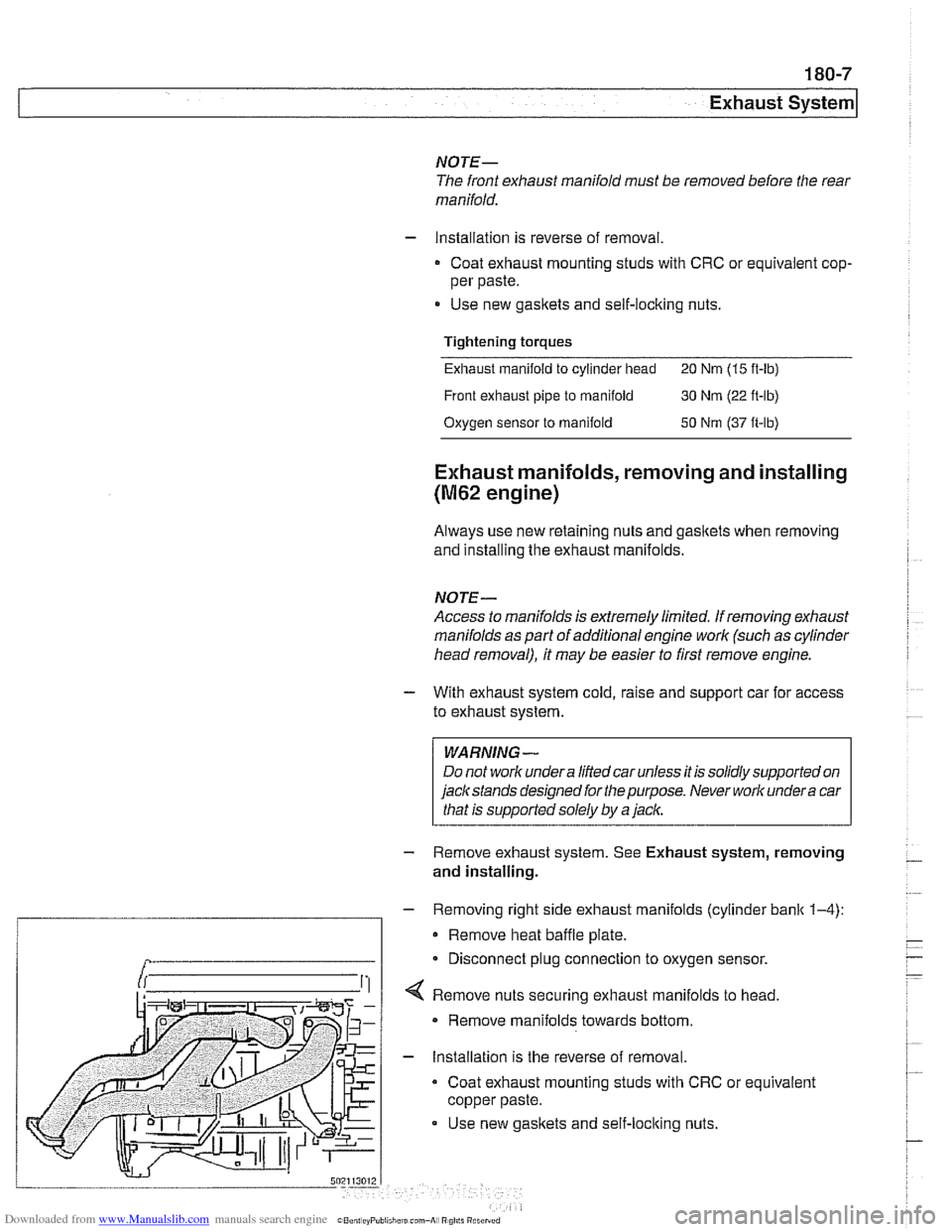
- Removing right side exhaust manifolds (cylinder bank 1-4):
Remove heat baffle plate.
Disconnect plug connection to oxygen sensor.
securing exhaust manifolds to head.
Remove manifolds towards bottom.
- Installation is the reverse of removal.
Coat exhaust mounting studs with CRC or equivalent
copper paste.
Use new gasltets and self-loclting nuts.