check engine BMW 528i 1998 E39 Workshop Manual
[x] Cancel search | Manufacturer: BMW, Model Year: 1998, Model line: 528i, Model: BMW 528i 1998 E39Pages: 1002
Page 504 of 1002
Downloaded from www.Manualslib.com manuals search engine
170-8
I Radiator and Cooling System
Common cooling system faults can be grouped into one of 4
categories:
Cooling system
lealts
Poor coolant circulation
Radiator cooling fan faults
Electrical/electronic faults
Cooling system inspection
- Check that coolant pump drive belt tensioner is functioning
properly and that belt tension is correct. Belt tensioner sys-
tems for the different models are shown in
020 Maintenance.
- Check condition of coolant pump drive belt.
- Checlc coolant hoses for cracks or softness. Checlc clamps
for looseness. Check coolant level and check for evidence of
coolant
lealts from engine.
- Check that radiator fins are not blocked with dirt or debris.
Clean radiator using low-pressure water or compressed air.
Blow outward, from engine side out.
- To check coolant pump:
Remove mechanical cooling fan. See Mechanical
(vis.
cous clutch) cooling fan, removing and installing.
Remove drive belt from coolant pump pulley. See
020
Maintenance.
Firmly grasp opposite sides of pulley and check for play in
all directions.
Spin pulley and check that shaft runs smoothly without
play.
NOTE-
The coolant provides lubrication for the pump shaft, so an oc-
casional drop of coolant
lealing from the pump is acceptable.
If coolant drips steadily from the vent hole, replace the pump.
- At normal engine operating temperature, cooling system is
pressurized. This raises boiling point of coolant.
Leaks may
prevent system from becoming pressurized. If visual evi-
dence is inconclusive, pressure test cooling system as de-
scribed later to help pinpoint hard-to-find leaks.
- If cooling system is full of coolant and holds pressure:
- Use an appropriate scan tool to interrogate engine control
module (ECM) for radiator fan or DME control circuit faults.
Checlc for loose or worn drive belt.
0 Test for failed thermostat or coolant pump impeller. Some
pumps may be fitted with plastic impellers.
Page 505 of 1002
Downloaded from www.Manualslib.com manuals search engine
Radiator and Cooling System
Check for cloggedlplugged radiator or coolant passages.
Cooling system pressure test
A cooling system pressure tester is used to test for coolant
leaks, including internal ones. Common sources of internal
coolant leaks are a faulty cylinder head gasket, a
craclted cyl-
inder head, or a cracked engine block.
WARNING-
At normal operating temperature the cooling system is pres-
surized. Allow the system to cool before opening. Release
the cap slowly to allow safe release ofpressure.
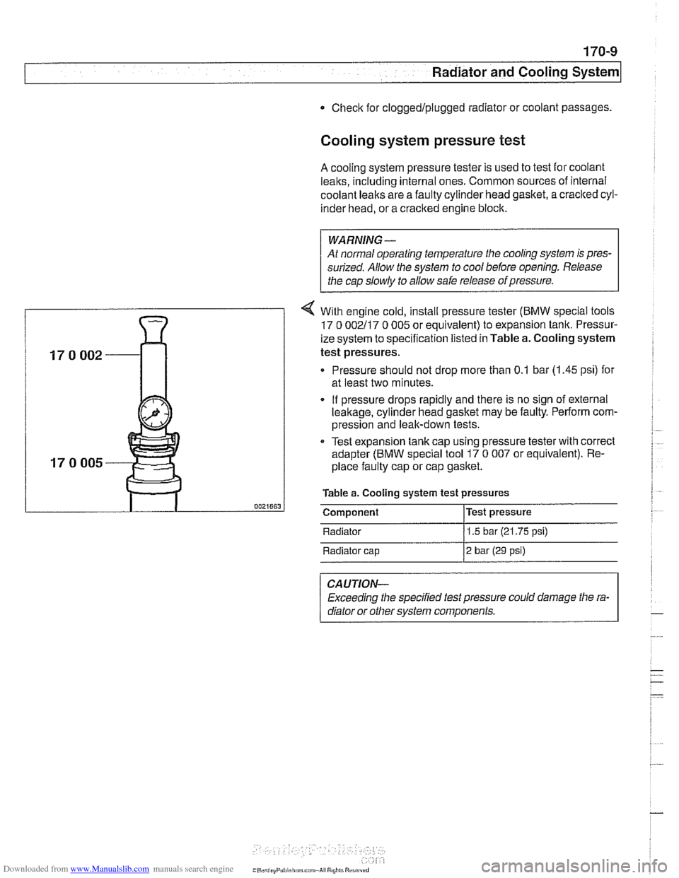
4 With engine cold, install pressure tester (BMW special tools
17 0 002117 0 005 or equivalent) to expansion tank. Pressur-
ize system to specification listed in Table a. Cooling system
test pressures.
Pressure should not drop more than 0.1 bar (1.45 psi) for
at least two minutes.
. If pressure drops rapidly and there is no sign of external
leakage, cylinder head gasket may be faulty. Perform com-
pression and leak-down tests.
Test expansion
tank cap using pressure tester with correct
adapter (BMW special tool 17
0 007 or equivalent). Re-
place faulty cap or cap gasket.
Table a. Cooling system test pressures
0021663 I Component l~est pressure
Radiator
11.5 bar (21.75 psi)
Radiator cap
12 bar (29 psi)
CAUTION-
Exceeding the specified test pressure could damage the ra-
diator or other svstem
com~onents.
Page 510 of 1002
Downloaded from www.Manualslib.com manuals search engine
Radiator and Cooling System
Cooling system, bleeding
Trapped air in the cooling system can prevent proper coolant
circulation and overheating. Wheneverthe coolant is drained
and filled, bleed the cooling system to remove trapped air.
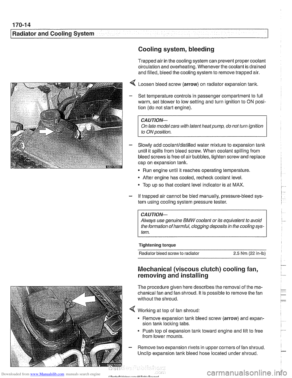
4 Loosen bleed screw (arrow) on radiator expansion tank.
- Set temperature controls in passenger compartment to full
warm, set blower to low setting and turn ignition to
ON posi-
tion (do not start engine).
CAUTIOIG
On late model cars with latent heat pump, do not turn ignition
to ON position.
- Slowly add coolanUdistilled water mixture to expansion tank
until it spills from bleed screw. When coolant spilling from
bleed screws is free of air bubbles, tighten screw and replace
cap on expansion tank.
Run engine until it reaches operating temperature,
- After engine has cooled, recheck coolant level.
Top up so that coolant level indicator is at MAX.
- If trapped air cannot be bled manually, pressure-bleed sys-
tem using cooling system pressure tester.
CA UTlON--
Always use genuine BMW coolant or its equivalent to avoid
the formation of harmful, clogging deposits
in the cooling sys-
tem.
Tightening torque
Radiator bleed screw to radiator 2.5 Nm (22 in-lb)
Mechanical (viscous clutch) cooling fan,
removing and installing
The procedure given here describes the removal of the me-
chanical fan and fan shroud. It is possible to remove the fan
without the shroud.
< Working at top of fan shroud:
Remove expansion tank bleed screw (arrow) and expan-
sion tank locking tabs.
Push top of expansion
tank toward engine and lift to free
from lower mounts.
- Remove two expansion rivets in upper corners of fan shroud.
Unclip expansion tank bleed hose located under shroud.
Page 527 of 1002
Downloaded from www.Manualslib.com manuals search engine
Exhaust system1
Exhaust manifold removal procedures are organized accord-
ing to engine code. If necessary, see
100 Engine-General
for engine code and application information.
Exhaust manifolds, removing and installing
(M52 engine)
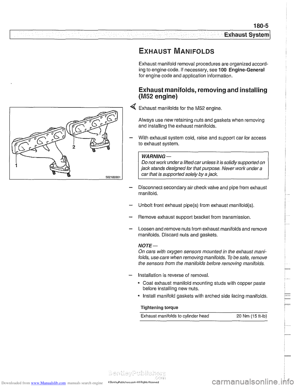
4 Exhaust manifolds for the M52 engine.
Always use new retaining nuts and gaskets when removing
and installing the exhaust manifolds.
- With exhaust system cold, raise and support car for access
to exhaust system.
WARNING -
Do not work under a lined car unless it is solidly supported on
jack stands designed for that purpose. Never work under a
car that is supported solely by a jack.
- Disconnect secondary air check valve and pipe from exhaust
manifold.
- Unbolt front exhaust pipe@) from exhaust rnanifold(s)
- Remove exhaust support bracket from transmission.
- Loosen and remove nuts from exhaust manifolds and remove
manifolds. Discard nuts and gaskets.
NOTE-
On cars with oxygen sensors mounted in the exhaust mani-
folds, use care when removing manifolds.
To be safe, remove
the sensors from the manifolds before removing manifolds.
- Installation is reverse of removal
Coat exhaust manifold mounting studs with copper paste
before installing new nuts.
Install manifold gaskets with arched side facing manifolds.
Tightening torque
Exhaust manifolds
to cylinder head 20 Nm (15 ft-lb)
Page 528 of 1002
Downloaded from www.Manualslib.com manuals search engine
180-6
Exhaust System
Exhaust manifolds, removing and installing
(M52 TU and M54 engines)
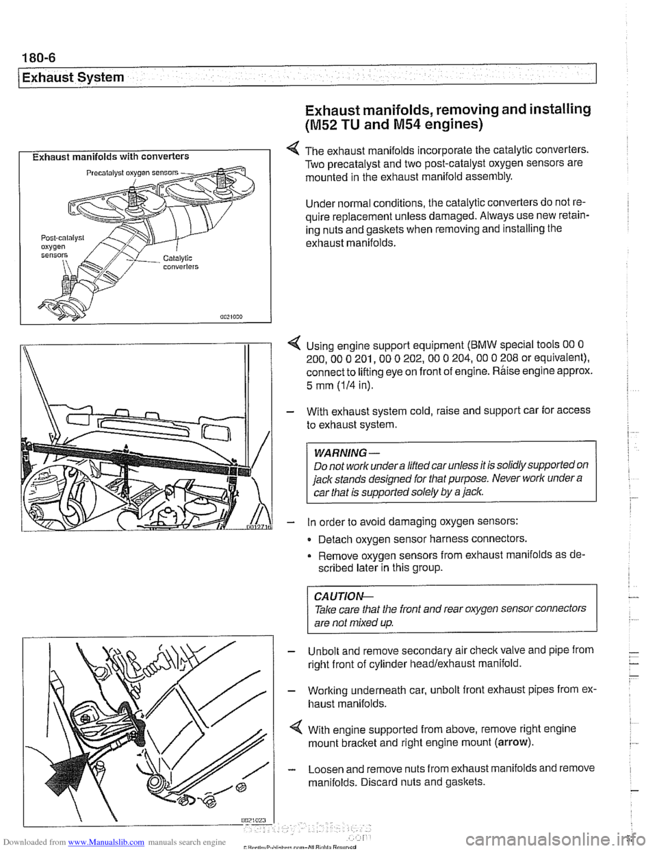
I Exhaust manifolds with converters I 4 The exhaust manifolds incorporate the catalytic converters.
Two precatalyst and two post-catalyst oxygen sensors are
mounted in the exhaust manifold assembly.
Under normal conditions, the catalytic converters do not re-
quire replacement unless damaged. Always use new retain-
ing nuts and gaskets when removing and installing the
exhaust manifolds.
I\
1 4 Using engine support equipment (BMW special tools 00 0
200. 00 0 201. 00 0 202.00 0 204.00 0 208 or equivalent).
connect to
lifting eye on front of engine. Rhise engine approx.
/I 1
5 mm (IH in).
With exhaust system cold, raise and support car for access
to exhaust system.
WARNING-
Do not worlc undera liftedcar unless it is solidly supported on
jack stands designed for that purpose. Never worlc under
a
car that is supported solely by a jaclc.
in order to avoid damaging oxygen sensors:
- Detach oxygen sensor harness connectors,
Remove oxygen sensors from exhaust manifolds as de-
scribed later in this group.
Unbolt and remove secondary air
checkvalve and pipe from
right front of cylinder headlexhaust manifold.
Working underneath car, unbolt front exhaust pipes from ex.
haust manifolds.
With engine supported from above, remove right engine
mount
bracket and right engine mount (arrow).
Loosen and remove nuts from exhaust manifolds and remove
manifolds. Discard nuts and gaskets.
CA UTIOG
Take care tliat the front and rear oxygen sensor connectors
are not mixed up.
-
Page 551 of 1002
Downloaded from www.Manualslib.com manuals search engine
- Raise and safely support vehicle
WARNING-
Make sure the car is stable and well supporied at all times.
Use a professional automotive /iff orjack stands designed for
the
ournose. A floor jack is not adeouate suooort.
- If necessary, remove transmission splash shield.
- Disconnect fluid line from slave cylinder on lefl side of trans-
mission. Place pan under hose to catch dripping fluid.
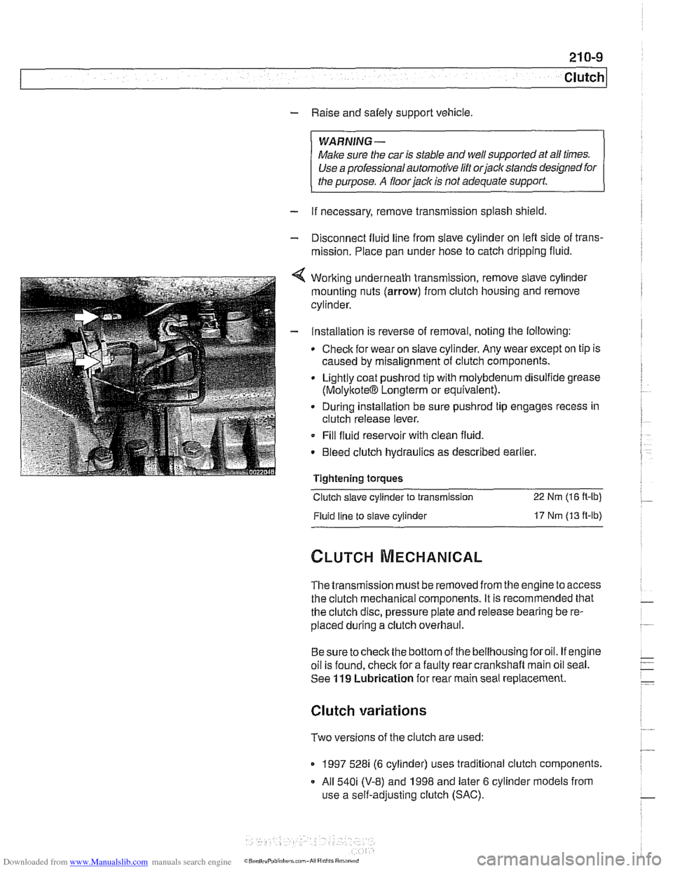
4 Working underneath transmission, remove slave cylinder
mounting nuts (arrow) from clutch housing and remove
cylinder.
- Installation is reverse of removal, noting the following:
Check for wear on slave cylinder. Any wear except on tip is
caused by misalignment of clutch components.
Lightly coat
pushrod tip with molybdenum disulfide grease
(MolyltoteIB Longterm or equivalent).
. During installation be sure pushrod tip engages recess in
clutch release lever.
Fill fluid reservoir with clean fluid.
. Bleed clutch hydraulics as described earlier.
Tightening
toraues - -.
Clutch slave cylinder to transmission 22 Nm (16 R-lb)
Fluid line to slave cylinder 17 Nm (13 ft-lb)
The transmission must be removed from the engine to access
the clutch mechanical components. It is recommended that
the clutch disc, pressure plate and release bearing be re-
placed during a clutch overhaul.
Besure tocheck the bottom of the bellhousing foroil. If engine
oil is found, check for a faulty rear crankshaft main oil seal.
See
119 Lubrication for rear main seal replacement.
Clutch variations
Two versions of the clutch are used:
1997 528i (6 cylinder) uses traditional clutch components.
All
540i (V-8) and 1998 and later 6 cylinder models from
use a self-adjusting clutch (SAC).
Page 556 of 1002
Downloaded from www.Manualslib.com manuals search engine
210-1 4
1 Clutch
Dowel sleeve I
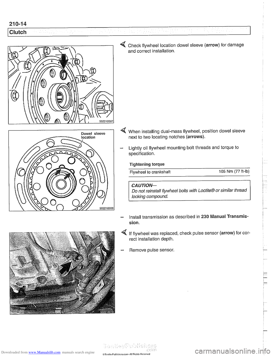
Check flywheel location
and correct installation. dowel sleeve
(arrow)
for . damage
< When installing dual-rnass flywheel, position dowel sleeve
next to two locating notches (arrows).
- Lightly oil flywheel mounting bolt threads and torque to
specification.
Tightening torque
Flywheel to crankshaft 105 Nm (77 ft-lb)
CAUTIOI\C
Do not reinstall flywheel bolls with LoctiteCTJ or similar thread
locl~ing compound.
- Install transm~ssion as descr~bed in 230 Manual Transmis-
sion.
4 If flywheel was replaced, check pulse sensor (arrow) for cor.
rect installation depth.
- Remove pulse sensor.
Page 565 of 1002
Downloaded from www.Manualslib.com manuals search engine
230 Manual Transmission
General ........................... .23 0.2 Output shaft
seal. replacing (5-speed
.... Special tools ........................ .23 0.2 transmission) (transmission installed) 230-10
Manual transmission aoolications ....... .23 0.5 Output shaft seal. replacing (6-speed . . .... transmission) (transmission installed) 230-12 ........ Transmission Fluid Service .23 0.6 put shaft seal. replacing
Transmission fluid level. checking ....... .23 0.6 (transmission ............... 230-15
........... Transmission fluid, replacing .23 0.6
Transmission Removal ................... ..... Transmission External Service .23 0-7 and installation 230-1
Back-up light switch, replacing .......... .23 0-' Transmission, removing and installing 230-16 ...
Selector shaft seal. reolacina .
(transmission installed) ................ .23 0.8
Page 570 of 1002
Downloaded from www.Manualslib.com manuals search engine
230-6
Manual Transmission
Manual transmissions installed in the 5 Series are normally
filled with a "Lifetime" manual transmission fluid
(BMW MTF
LT-I) and do not require periodic fluid changes. Transmis-
sions filled with MTF LT-I lifetime oil are identified with a yel-
low label near the transmission fill plug labeled "Lifetime Oil
MTF-LT-1".
Transmission fluid level, checking
- Drive vehicle for a few miles to warm transmission.
- Raise and safely support vehicle to access transmission
filler plug.
CAUTION-
Make sure the car is stable and well supporfedat all times.
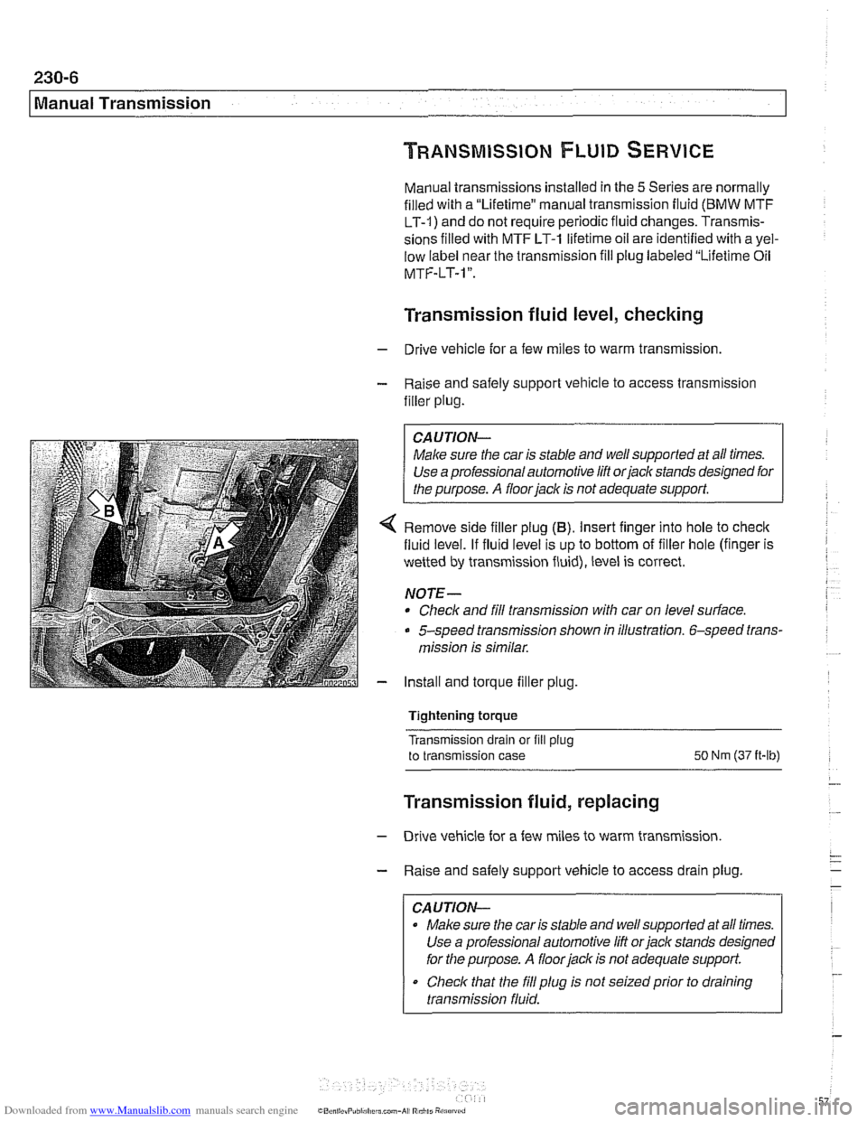
4 Remove side filler plug (B). Insert finger into hole to check
fluid level. If fluid level is up to bottom of filler hole (finger is
wetted by transmission fluid), level is correct.
NOTE-
* Check and fill transmission with car on level surface.
5-speed transmission shown in illustration. 6-speed trans-
mission is similar.
- Install and torque filler plug.
Tightening torque
Transmission drain or fill
plug
to transmission case SO Nm (37 it-lb)
Transmission fluid, replacing
- Drive vehicle for a few miles to warm transmission.
- Raise and safely support vehicle to access drain plug.
CAUTION-
Make sure the car is stable and well supported at all times.
Use a professional automotive lift
orjack stands designed
for the purpose.
A floor jack is not adequate support.
Check that the
fill plug is not seizedprior to draining
transmission fluid.
Page 573 of 1002
Downloaded from www.Manualslib.com manuals search engine
230-9
Manual ~ransmissionl
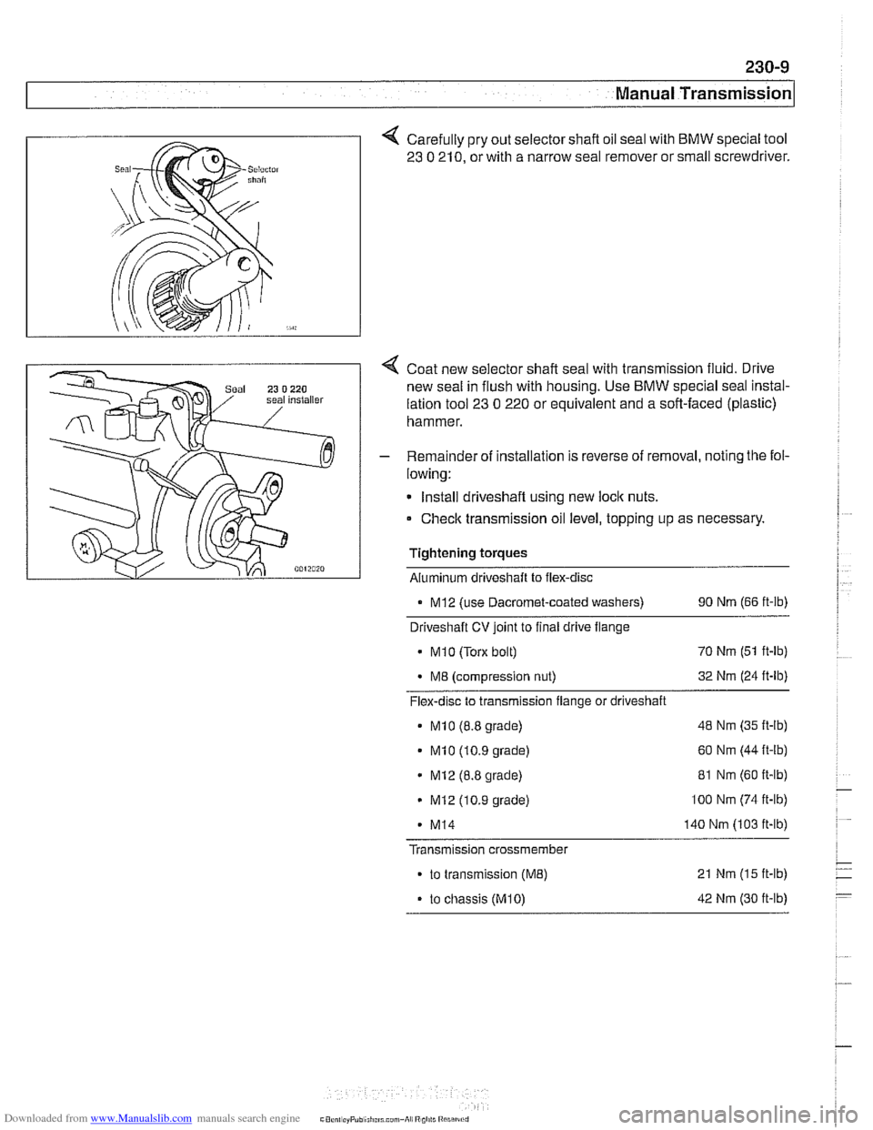
Carefully pry out selector shaft oil seal with BMW special tool
23
0 210, or with a narrow seal remover or small screwdriver.
Coat new selector shaft seal with transmission fluid. Drive
new seal in flush with housing. Use
BMW special seal instal-
lation tool
23 0 220 or equivalent and a soft-faced (plastic)
hammer.
- Remainder of installation is reverse of removal, noting the fol-
lowing:
Install driveshaft using new
loclc nuts.
Check transmission oil level, topping up as necessary.
Tightening torques Aluminum driveshaft to flex-disc
. MI2 (use Dacromet-coated washers) 90 Nm (66 ft-lb)
Driveshaft CV joint to final drive flange
MI 0 (Torx bolt) 70
Nm (51 ft-lb)
M8 (compression nut) 32
Nm (24 ft-lb)
Flex-disc to transmission flange or driveshaft
MI0 (8.8 grade) 48 Nm (35 ft-lb)
MI0 (10.9 grade) 60
Nm (44 it-lb)
MI2 (8.8 grade) 81
Nm (60 ft-lb)
MI2 (10.9 grade) lo0 Nm (74 ft-lb)
- MI4 140 Nm (103 ft-lb)
Transmission crossmember
to transmission (ME) 21 Nm (15 ft-lb)
. to chassis (M10) 42 Nm (30 ft-lb)