check engine BMW 528i 1998 E39 Workshop Manual
[x] Cancel search | Manufacturer: BMW, Model Year: 1998, Model line: 528i, Model: BMW 528i 1998 E39Pages: 1002
Page 575 of 1002
Downloaded from www.Manualslib.com manuals search engine
230-1 1
Manual ~ransmissionl
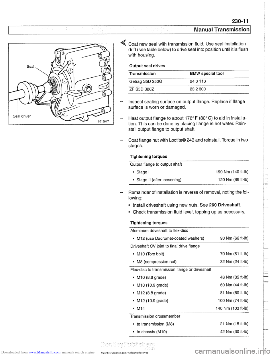
Coat new seal with transmission fluid. Use seal installation
drift (see table below) to drive seal into position until it is flush
with housing.
Output seal drives
Transmission
BMW special tool
Getrag S5D 250G 240110
ZF S5D 3202 23 2 300
inspect sealing surface on output flange. Replace if flange
surface is worn or damaged.
Heat output flange to about 176"
F (80" C) to aid in installa-
tion. This can be done by placing flange in hot water. Rein-
stall output flange to output shaft.
- Coat flange nut with LoctiteB243 and reinstall. Torque in two
stages.
Tightening torques Output flange to output shaft
Stage I 190 Nm (140 ft-lb)
Stage II (after loosening) 120
Nm (89 ft-lb)
- Remainder of installation is reverse of removal, noting the fol-
lowing:
Install driveshaft using new nuts. See
260 Driveshaft.
Check transmission fluid level, topping up as necessary
Tightening torques Aluminum driveshaft to flex-disc
- MI2 (use Dacromet-coated washers) 90 Nm (66 ft-lb)
Driveshaft
CV joint to final drive flange
. MI0 (Torx bolt) 70
Nm (51 ft-lb)
. M8 (compression nut) 32
Nm (24 ft-lb)
Flex-disc to transmission flange or driveshaft
- MI0 (8.8 grade) 48
Nm (35 ft-lb)
- MI0 (10.9 grade) 60
Nm (44 It-lb)
. MI2 (8.8 grade) 81 Nm (60 ft-lb)
. MI2 (10.9 grade) I00 Nm (74 It-lb)
M14 140 Nm (103 It-lb)
Transmission crossmember
- to transmission (ME) 21 Nm (15 It-lb)
- to chassis (M10) 42 Nm (30 It-lb)
Page 585 of 1002
Downloaded from www.Manualslib.com manuals search engine
240 Automatic Transmission
General . . . . . . . . . . . . . . . . . . . . . .
Special tools . . . . . . . . . . . . . . . . . . .
Automatic transmission applications
. . . . . ,240-2 ATF, draining and filling . . . . . . . . . . . . . . . . 240-7
. . . . . ,240-2 Automatic transmission fluid
. . . . . ,240-4 pan and strainer. . . . . . . . . . . . . . . . . . . . . . 240-9
Troubleshooting . . . . . . . . . . . . . . . . . . .240-4 Transmission Removal
and Installation
. . . . . . . . . . . . . . . . . . . 240-10 Automatic Transmission Fluid Transmission, removing and installing . . . 240-10 (ATF) Service . . . . . . . . . . . . . . . . . . . . . ,240-6
Automatic transmission fluid (ATF) . . . . . . . ,240-6
ATF level, checking . . . . . . . . . . . . . . . . . . ,240-6
Page 589 of 1002
Downloaded from www.Manualslib.com manuals search engine
- .- -
Automatic Transmission
Electronics are used to control the operation of these auto-
matic transmissions. Steptronic transmission functions are
also programmed into the transmission control module
(TCM). The TCM monitors transmission operation for faults
and alerts the driver by illuminating the transmission fault indi-
cator on the instrument panel. Diagnostic trouble codes
(DTCs) stored in the TCM may be downloaded and interpret-
ed by trained technicians using special BMW diagnostic
equipment.
Some minor automatic transmission problems can be cor-
rected by changing the automatic transmission fluid (ATF)
and filter. Begin by checking ATF level and condition.
Checlc
to see if the fluid is dirty or has a burned odor indicating over-
heated fluid. The burned odor may be the results of burned
discs in theclutch paclts. The friction material from the burned
disc can clog valve body passages.
NOTE-
The E39 automatic transmission is not equipped with a dip-
stick.
Checking the ATF level must be done while monitoring
the ATF temperature with the engine idling. The
BMW dealer
is equipped with the special equipment to make this check.
Page 590 of 1002
Downloaded from www.Manualslib.com manuals search engine
240-6
I Automatic Transmission Automatic transmission fluid (ATF)
The E39 automatic transmission is filled with either Dexron Ill
ATF or Texaco 80728, a life time oil.
CA UTIOI\C
Use only the transmission fluid that is approved for use by
BMW All other fluids will cause non warrantable transmis-
I sion damage.
Mixing different types of transmission fluids will lead to
transmission failure.
NOTE-
The type of transmission lubricant used can be found on a
stickeron the transmission pan. Dexron
111ATF (blacksticker)
reads "ATF-Oil': Special life time oil (green sticker) reads
'Life-Time Oil': If in doubt, consult an authorized
BMW dealer
for alternate fluid use and current information regarding
transmission operating fluids.
ATF level, checking
Check ATF level if there is evidence of a leak, a complaint re-
lated to fluid level or afler transmission repairs.
The automatic transmission is not equipped with a dipstick.
Checking the ATF level requires that the transmission be at
operating temperature during the checking procedure.
NOTE-
Vehicle must be level throughout tests
- Drive vehicle to warm up ATF to operating temperature.
- Connect BMW diagnostic scan tool DiSplus, MoDiC, GTI or
equivalent to determine transmission oil temperature.
ATF level checking
Fluid temperature
30' - 50°C (85' - 120" F)
- With engine running, switch on air conditioning to increase
engine idle speed.
- Apply parking brake.
- While applying foot brake firmly move gear shift selector
lever through
all gear positions, pausing in each gear briefly.
Page 591 of 1002
Downloaded from www.Manualslib.com manuals search engine
Automatic Transmission
- Raise and safely support vehicle.
CA U JIOG
Male sure the car is stable and well supported at all times.
Use a professional automotive lift
orjack stands designed for
the purpose. A floorjack is not adequate support
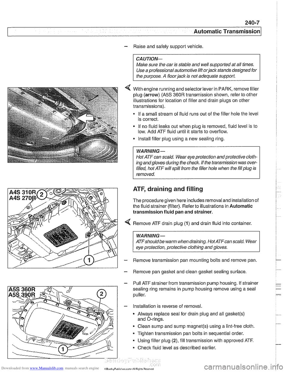
4 With engine running and selector lever in PARK, remove filler
plug (arrow)
(A5S 360R transmission shown, refer to other
illustrations for location of filler and drain plugs on other
transmissions).
If a small stream of fluid runs out of the filler hole the level
is correct.
If no fluid
leaks out when plug is removed, fluid level is to
low. Add ATF fluid until it starts to overflow.
Install filler plug using a new sealing ring.
Hot ATF can scald. Wear eye protection and protective cloth-
ing andgloves during
the check. If the tmnsmission was over-
filled, hot ATF will spill from the filler hole when the
fill plug is
removed.
ATF, draining and filling
The procedure given here includes removal and installation of
the fluid strainer (filter). Refer to illustrations in Automatic
transmission fluid
pan and strainer.
Remove ATF drain plug
(1) and drain fluid into container.
WARNING-
ATFshould be warm when draining. Hot ATFcan scald. Wear
eye protection, protective clothing and gloves.
Remove transmission pan mounting bolts and remove pan.
Remove pan gasket and clean
gasket sealing surface.
- Pull ATF strainer from transmission pump housing. If strainer
sealing ring remains in pump housing remove using a seal
puller.
- Installation is reverse of removal.
Always replace seal for drain plug and all
gasket(s)
and O-rings.
Clean sump and sump
magnet(s) using a lint-free cloth.
Tighten transmission pan bolts in sequential order.
Using filler plug
(2), fill transmission with approved ATF.
Check fluid level as described earlier.
Page 597 of 1002
Downloaded from www.Manualslib.com manuals search engine
240-1 3
Automatic ~ransmissionl
- Blow out oil cooler lines with low-pressure compressed air
and flush cooler with clean ATF twice before reattaching lines
to transmission.
CA UTIOG
Wear safety glasses when worling with compressed air:
@ Do not reuse ATF used for flushing.
- Remainder of installation is reverse of removal, noting the fol-
lowing:
Reinstall driveshafl using new nuts.
Install new sealing washers on transmission cooling line
banjo bolts.
Install new O-rings on transmission cooler lines, where
applicable.
Inspect engine drive plate (flywheel) for cracks or elongat-
ed holes. Replace
if necessary.
Be sure bellhousing alignment dowel sleeves are located
correctly. Replace damaged sleeves.
Checlc to be sure torque converter is seated correctly in
transmission during final installation.
Use
BMW special tool 24 2 300 to align three mounting
tabs on torque converter with indentations on drive plate
(flywheel).
Fill transmission with clean ATF until oil level is even with
fill hole. Then check fluid level as described earlier.
Adjust gearshift mechanism. See
250 Gearshift Linkage.
NOTE-
In order to avoid difficulties in transmission removal at a fu-
ture time, use washers with Torx-head mounting bolts.
Page 599 of 1002

Downloaded from www.Manualslib.com manuals search engine
250-1
250 Gearshift Linkage
General ........................... ,250-2 Automatic Transmission Gearshift. .. 250-6
Special tools
........................ ,250-2 Gearshift mechanism, adiustina -
(automatic transmission) ............... 250-6 Manual Transmission Gearshift ..... ,250-3 Automatic shiftlock, checking function Gearshift lever, removing
(automatic transmission) ............... 250-7
(manual transmission) ................ ,250-3 Shift interlock, checking function
Gearshift lever, installing
(automatic transmission)
............... 250-8 (manual transmission) ................ ,250-4
Page 605 of 1002
Downloaded from www.Manualslib.com manuals search engine
250-7
Gearshift ~inka~el
Automatic shiftlock, checking function (automatic transmission)
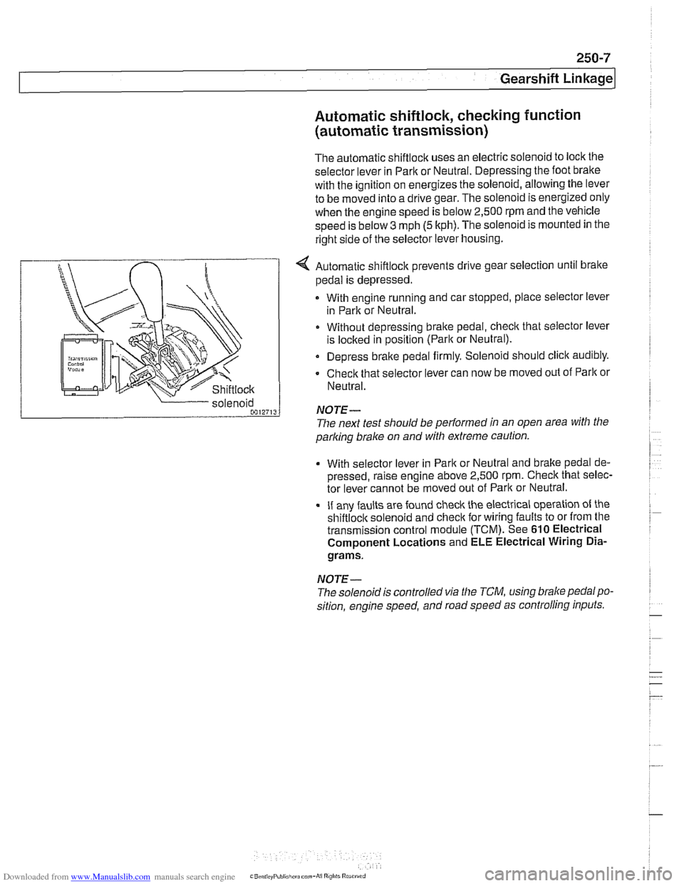
The automatic shiftlock uses an electric solenoid to lock the
selector lever in Park or Neutral. Depressing the foot bralte
with the ignition on energizes the solenoid, allowing the lever
to be moved into a drive gear. The solenoid is energized only
when the engine speed is below 2,500 rpm and the vehicle
speed is below
3 mph (5 kph). The solenoid is mounted in the
right side of the selector lever housing.
... nir r
Shiftlock
4 Automatic shiftlock prevents drive gear selection until brake
pedal is depressed.
With engine running and car stopped, place selector lever
in Park or Neutral.
Without depressing bralte pedal, check that selector lever
is
loclted in position (Parlt or Neutral).
Depress brake pedal firmly. Solenoid should click audibly.
Check that selector lever can now be moved out of
Parlt or
Neutral.
parking
brake on and with extreme caution.
solenoid
0012713
With selector
lever in Park or Neutral and bralte pedal de-
pressed, raise engine above 2,500
rpm. Check that selec-
tor lever cannot be moved out of Park or Neutral.
If any faults are found check the electrical operation of the
shiftloclt solenoid and checlt for wiring faults to or from the
transmission control module (TCM). See
610 Electrical
Component Locations and ELE Electrical Wiring
Dia-
grams.
NOTE-
NOTE-
The solenoidis controlled via the TCM, using brake pedalpo-
sition, engine speed, and road speed as controlling inputs.
The
next test should be performed in an open area with the
Page 606 of 1002
Downloaded from www.Manualslib.com manuals search engine
250-8
Gearshift Linkage
-;Ag Gate "",?it.,
Shift interlock, checking function
(automatic transmission)
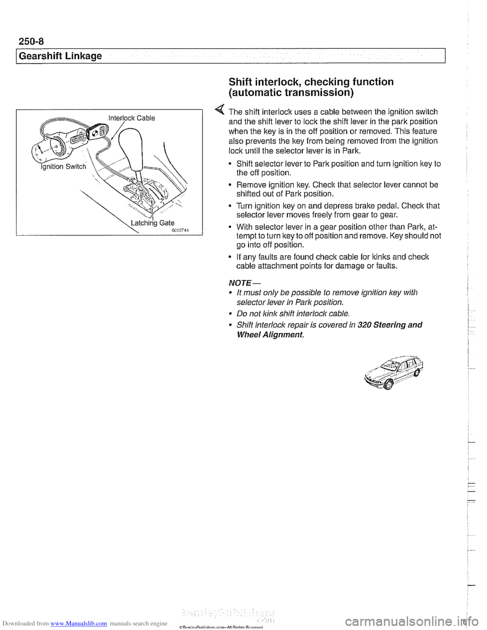
4 The shift interlock uses a cable between the ignition switch
and the shift lever to lock the shift lever in the park position
when the key is in the off position or removed. This feature
also prevents the key
from being removed from the ignition
lock until the selector lever is in Park.
Shift selector lever to Park position and turn ignition key to
the off position.
Remove ignition key. Checlc that selector lever cannot be
shifted out of Park position.
Turn ignition lkey on and depress
brake pedal. Checlc that
selector lever moves freely from gear to gear.
With selector lever in a gear position other than Park, at-
tempt to turn lkey to off position and remove. Key should not
go into off position.
If any faults are found check cable for lkinks and
check
cable attachment points for damage or faults.
NOTE-
* It must only be possible to remove ignition ley with
selector lever
in Park position.
* Do not link shift interlocl( cable.
Shift interlock repair is covered
in 320 Steering and
Wheel Alignment.
Page 609 of 1002
Downloaded from www.Manualslib.com manuals search engine
Driveshaft
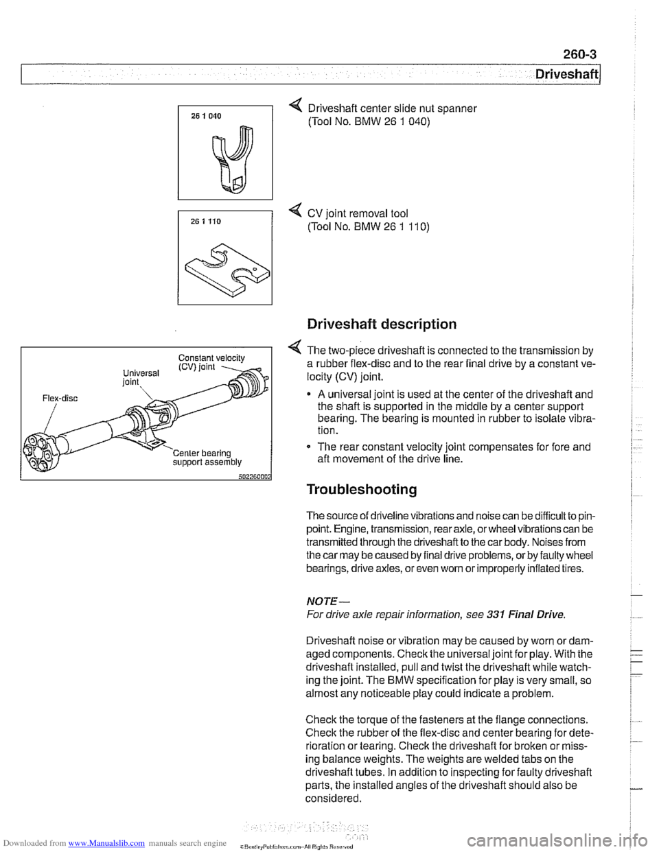
4 Driveshaft center slide nut spanner
(Tool No. BMW
26 1 040)
7, 25 1 Ho 4 cv joint removal tool
(Tool No. BMW 26 1 11 0)
support assembly
Driveshaft description
4 The two-piece driveshaft is connected to the transmission by
a rubber flex-disc and to the rear final drive by a constant ve-
locity (CV) joint.
A universal joint is used at the center of the driveshaft and
the shaft is supported in the middle by a center support
bearing. The bearing is mounted in rubber to isolate vibra-
tion.
- The rear constant velocity joint compensates for fore and
aft movement of the drive line.
Troubleshooting
The source of driveline vibrations and noise can be difficultto pin-
point. Engine, transmission, rear axle, or wheel vibrations can be
transmitted through thedriveshaftto the car body. Noises from
thecar may be caused by final drive problems, or by faulty wheel
bearings, drive axles, or even
wom or improperly inflated tires.
NOTE-
For drive axle repair information, see 331 Final Drive
Driveshaft noise or vibration may be caused by worn
ordam-
aged components. Check the universal joint for play. With the
driveshaft installed, pull and twist the driveshaft while watch-
ing the joint. The
BMW specification for play is very small, so
almost any noticeable play could indicate a problem.
Check the torque of the fasteners at the flange connections.
Check the rubber of the flex-disc and center bearing for dete-
rioration or tearing. Check the driveshaft for broken or miss-
ing balance weights. The weights are welded tabs on the
driveshaft tubes. In addition to inspecting for faulty driveshaft
parts, the installed angles of the driveshaft should also be
considered.